Intensification Of Low Energy Nuclear Reactions ... - LENR-CANR
Intensification Of Low Energy Nuclear Reactions ... - LENR-CANR
Intensification Of Low Energy Nuclear Reactions ... - LENR-CANR

You also want an ePaper? Increase the reach of your titles
YUMPU automatically turns print PDFs into web optimized ePapers that Google loves.
4 Electrolytic Cells<br />
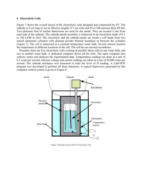
Figure 7 shows the overall layout of the electrolytic cells designed and constructed by ET. The<br />
cathode is 8 cm long (6 cm in effective length), 0.7 cm wide and 50 or 100 microns thick Pd foil.<br />
Two platinum foils of similar dimensions are used for the anode. They are located 5 mm from<br />
each side of the cathode. The cathode-anode assembly is immersed in an electrolyte made of 0.1<br />
to 1M LiOD in D2O. The electrolyte and the cathode-anode are inside a cell made from two<br />
nested aluminum cylinders with alumina powder thermal insulation in between the cylinders<br />
(Figure 7). The cell is immersed in a constant temperature water bath. Several sensors monitor<br />
the temperature in different locations in the cell. The cell has an external recombiner.<br />
Presently there are five electrolytic cells working in parallel; three cells in one water bath, and<br />
two in another water bath. A dedicated computer drives all the cells. The same computer also<br />
collects, stores and analyzes the experimental data. Temperatures readings are done at a rate of<br />
0.3 scans per second, whereas voltage and current readings are taken at a rate of 50,000 scans per<br />
second. The cathode resistance was measured to infer the level of D loading. A LabVIEW<br />
program was developed to perform all these functions. A typical Superwave generated by this<br />
computer control system is given in Figure 8.<br />
Figure 7 Schematic layout of the ET electrolytic cells