Peavy Classic 30 Mods - The Blue Guitar
Peavy Classic 30 Mods - The Blue Guitar
Peavy Classic 30 Mods - The Blue Guitar

Create successful ePaper yourself
Turn your PDF publications into a flip-book with our unique Google optimized e-Paper software.
<strong>Peavy</strong> <strong>Classic</strong> <strong>30</strong> <strong>Mods</strong><br />
Overview<br />
Retubing<br />
<strong>The</strong> <strong>Blue</strong> <strong>Guitar</strong><br />
Many of us have bought the <strong>Peavy</strong> <strong>Classic</strong> <strong>30</strong> because it is a nice-sounding, small-sized, vintage-looking<br />
yet economical tube amp with a good voice for guitar leads (or miked harmonica). After playing it for<br />
awhile, its limitations become obvious: as tubed from the factory, the sound can be overly harsh, the bass<br />
response is very thin, and the boost switch radically alters the tone as well as the gain so it is unusable for<br />
many guitarists looking for vintage sounds. After a few months, I put it in the back of my closet, deciding<br />
that it was more of a "toy" amp than a real amp. Many amp techs have mentioned that customers would<br />
bring in <strong>Classic</strong> <strong>30</strong>'s to see if anything could be done to improve the tone; however with the small<br />
transformers and printed circuit board design they were reluctant to promise any improvements that would<br />
justify the costs involved. As a hobbyist with a <strong>Classic</strong> <strong>30</strong> sitting around just gathering dust I figured I might<br />
as well try out some different mods to see if I could get some better tones out of the amp. After doing the<br />
mods outlined in this article, the amp captures the sounds I've been looking for. You may want to try<br />
changing some of the values I recommend to capture the sound you are looking for.<br />
Check out my Righteous Tubes! page for the details on the latest preamp tube combinations which seem to<br />
work best for me (as I find better combinations, I will revise that page).<br />
<strong>The</strong> <strong>Classic</strong> <strong>30</strong> uses 3 12AX7 preamp tubes, labelled V1, V2 and V3 from right to left as viewed from<br />
the rear of the amp. <strong>The</strong> C<strong>30</strong> isn't a true 2 channel amp; the channel select switch adds in the 2 additional<br />
gain stages of V2, between the initial and final preamp stages of V1. V3 uses both stages for the driver<br />
circuit before the 4 EL84 output tubes.<br />
As for which brands and styles of 12AX7 tubes that work best in the <strong>Classic</strong> <strong>30</strong>, let us address the V3<br />
driver tube first. If you are looking for clean guitar tones from the Normal channel, you will want to use a<br />
driver tube that is fairly transparent. I have found that the stock Chinese tubes that ship with the amp work<br />
well as driver tubes; for an even better sound, check out a Golden Dragon 12AX7 or Ruby Tubes 7025STR:<br />
they are very clean and transparent tubes with a little more gain than the stock tubes.<br />
<strong>The</strong> guitar signal goes directly to the first stage of V1 in all modes so its selection is very critical to the<br />
sound you are looking for. If you use the Normal channel a lot, you should choose a tube which sounds well<br />
in this mode. For crystal clarity (at the expense of lower gain), you can use a 5751 tube. I personally prefer<br />
the Sovtek 12AX7WBT+ because it produces a warmer tone, very similar to a vintage Telefunken. For V2<br />
(the 2 gain stages added in overdrive mode), I prefer the Sovtek 12AX7WB, which has lower gain than the<br />
WBT+. This tube is bypassed in the normal mode, so you can try out different tubes here to decide what<br />
works best for you in the overdrive mode.<br />
If you use the <strong>Classic</strong> <strong>30</strong> strictly in overdrive mode, you can try out higher gain tubes in all 3 positions,<br />
with one suggestion here. I always thought of changing preamp tubes as being like changing spark plugs in<br />
your car: decide which brand and style works best for you and replace them all with the same type. In trying<br />
out different tubes, what I found is that if all tubes are the same, it exaggerates the tonal characteristics of<br />
that particular tube. Perhaps that is exactly what you are looking for, but you can generally get a fuller sound<br />
if you mix and match different tubes. You may want to bring your amp down to your local music store and<br />
see if they will let you try out different combinations of preamp tubes.
General Information on mods for <strong>Classic</strong> <strong>30</strong><br />
Warning! Tube amps have high voltages inside of them, even when the amp is unplugged! <strong>The</strong> large power<br />
supply filter capacitors can be safely discharged using a well insulated test probe connected to the chassis<br />
ground through a 10K resistor. With the chassis removed from the cabinet and the FX jacks to your left you<br />
will notice several large 5 and 1 watt resistors mounted on stand-offs away from the board. Directly above<br />
from the Bass control is R58; with the insulated 10k resistor/probe short first the left lead and then the right<br />
lead. Directly above from the Pre gain pot is R59 mounted horizontally and R60 mounted vertically. With<br />
your special resistor probe, short first the left and then the right leads of R59, and then fisrt the back and the<br />
front leads of R60. Generally any charge will be drained through the OT (output transformer) after a minute<br />
or two, but its best not to take any chances.<br />
To remove the <strong>Classic</strong> <strong>30</strong> from the cabinet to work on it, first unscrew the reverb spring bag and cable<br />
straps, unplug the speaker and reverb leads, and then remove the 8 shoulder screws on the top and sides of<br />
the cabinet holding the chassis. I generally label tubes with their socket numbers using a Sharpie marker<br />
before I pull them out so I know where to put them back; this also helps in lining them up properly so you<br />
don't bend the pins. In putting the tubes back into the <strong>Classic</strong> <strong>30</strong>, the gap between pins 9 and 1 for the<br />
preamp tubes faces the front of the amp, and the gap for the output tubes faces the rear of the amp.<br />
To remove the 3-sided circuit board from the chassis, remove the chicken head knobs and unscrew the<br />
11/32" nuts holding down the 7 pots and 1/2" nuts securing the 5 jacks. Pull out the small jack board.<br />
Unplug the yellow and red wire harness from the power transformer as well as the yellow and blue speaker<br />
plug, two OT plugs (the lower OT plug is <strong>Blue</strong>-Red-Brown) and the reverb cable connector. Remove the 8<br />
black screws holding in the circuit board with the tube sockets and then gently push in first the tube sockets<br />
and then the pots to remove the 3-sided circuit board from the chassis (it should be free to come out<br />
completely). As I remove different components from the board, I tape them to the inside of the chassis and<br />
label them with the reference numbers and value in the event I want to reinstall them later.<br />
After taking the amp apart about a dozen times in developing these mods, I noticed that some of the pot<br />
bushings would not tighten down properly and that some of the chicken-head knobs were loose enough to<br />
rattle or slip. I found that teflon tape (for plumbing) works great for both of these problems; for the pot<br />
bushings wind a few wraps of the teflon tape clockwise around the bushing. For the loose knobs, fold over<br />
the tape so that it is about 4 layers thick and place it on the shaft before pushing the knob back on. If I am<br />
just making a quick test of a mod, I'll only replace maybe 3 of the pot nuts, and only tighten them down<br />
loosely. But be sure to tighten down the input and extension speaker jacks as these establish the grounds for<br />
the circuit board and power tubes.<br />
A few other tips: label the bottom of the knobs with a Sharpie permanent marker when you first take<br />
them off. Although they are all supposed to be identical, they will slip on some pots but not others. After<br />
having one of the grounds break on a reverb tank plug, I put heat shrink tubing on both of the plugs to help<br />
protect the solder connections. After unfolding the circuit board a dozen times, I found the hinged jumper<br />
wires starting to break; be careful when you unfold them and if you notice any copper showing through that<br />
means the wire is ready to break- either replace it with 22 ga bus wire or you can try reinforcing it with a<br />
short length of 24 ga bus wire.<br />
As for replacing components on a printed circuit board there are a few tricks I learned. Desoldering braid<br />
works better for small solder connections than a desoldering tool. Although you can get it at Radio Shack<br />
(#64-2090B), the Chem-Wik line carried at electronics parts houses uses a finer braid that is less abrasive to<br />
the board. Be sure to check all of the sections of the board you work on for solder bridges (which are short<br />
circuits between two traces). In the event that a solder trace breaks off when you are reworking the board<br />
you can reestablish the connection by bending the component lead over to where the trace had gone<br />
originally (check the layout drawing from <strong>Peavy</strong>). <strong>The</strong> bottom of the circuit board is covered with a<br />
protective coating; I'll polish a trace with the desolder braid and a dab of solder until the solder adheres to
the trace where I intend to run the lead. One last note on soldering: be sure to use a damp sponge to keep the<br />
tip clean.<br />
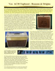
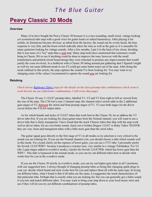
Tone Cap <strong>Mods</strong> for the <strong>Classic</strong> <strong>30</strong><br />
Modify the tonal response of this amp by replacing the tone and boost circuit caps!<br />
By changing the values and style of capacitors used in the tone and boost circuitry of the <strong>Classic</strong> <strong>30</strong>, the<br />
tonal response can be changed dramatically. Most amp builders and connoisseurs prefer Sprague-style<br />
Orange Drop caps for the midrange and bass caps; many of them likewise prefer silver mica caps for the<br />
treble caps.<br />
As for the values of the tone caps, <strong>Peavy</strong> uses a 270pf cap for treble and a pair of .022uf caps for<br />
midrange and bass. <strong>The</strong>y also use a .047uf cap in the boost circuit, which drastically increases the gain and<br />
midrange response of the preamp. <strong>The</strong> boost cap bypasses the treble cap, in effect raising the value of the<br />
treble cap to the sum of the two values. Because of the very high value used (most boost circuits use a 750pf<br />
to .0015 cap) a 220k resistor to ground is used to reducing popping when the boost circuit is switched in or<br />
out.<br />
For this mod, I recommend replacing the .022uf bass cap (C18) with a .047uf Orange Drop-style cap for<br />
improved bass response. (If you prefer a higher-gain overdrive tone, you may prefer to use a .022uf Orange<br />
Drop cap instead for a more midrangy sound). <strong>The</strong> .022uf midrange cap (C19) should be replaced with a<br />
.022uf Orange Drop. I put in a 270pf silver mica cap in place of the 270pf tubular ceramic treble cap (C14-<br />
it looks like a resistor but with a green body instead of a tan). However, the stock treble cap can be used if<br />
you can't find a silver mica cap.<br />
For the boost cap (C11), I recommend using a 750pf cap. With this value, the boost switch works similar<br />
to a Shift switch on an older Mesa Boogie amp: it kicks the volume up a notch and boosts the midrange<br />
response. For more boost and tonal shift, you can use a .001uf or .0015uf cap instead. Using smaller values<br />
such as these, the 220k resistor (R12) to ground could be eliminated or replaced with a very high value (I<br />
used a 2.2M resistor). With the stock boost cap, I found the gain boost and tonal shift to be too drastic to be<br />
usable for vintage blues tones. With the values I recommend, the boost switch offers an alternative voicing<br />
which retains much of the tone and character of the unboosted mode.<br />
If you choose to replace the boost cap with a lower value as recommended here, you will sacrifice much<br />
of the gain of the stock boost circuit. To recapture some of the gain lost I suggest that you replace the 100K<br />
plate load resistor for V3A with a 120K or 150K resistor as outlined later in this article. Click Here!<br />
<strong>The</strong> following drawing illustrates the location of the components in the tone and boost circuits:
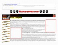
Overdrive Channel input mod for the <strong>Classic</strong> <strong>30</strong><br />
Replace C4 cap to tone down the harshness of the OD Channel.<br />
Another common complaint concerning the <strong>Classic</strong> <strong>30</strong> is that the Overdrive Channel is too harshsounding.<br />
After replacing the tone and boost caps as outlined above, I wasn't able to get a really nice sound<br />
from the OD channel unless I kicked in the Boost switch. In re-examining the schematic, I noticed that the<br />
signal from V1A is routed first through a .047uf coupling cap and then sent to both the Normal and OD<br />
channels. <strong>The</strong> Normal channel gets its signal from a .001uf cap paralleled with a 680k resistor, while the<br />
entire signal going to the OD channel is routed through a 470pf cap (C4)! A cap of that value will allow<br />
mainly treble and midrange frequencies through, and effectively blocks most of the low frequencies from<br />
V1A.<br />
To reduce the harshness of the OD channel, I recommend replacing C4 with a 820pf mica cap and C7<br />
with a 390pf mica cap. To locate C4, look for the 2 tubular caps (they look like resistors but with a green<br />
body) between the Normal volume pot and the Pre volume pot for OD channel; C4 is the tubular cap closer<br />
to the Pre volume pot and C7 is closer to the Normal volume pot. For a heavier distortion sound you can<br />
replace C4 with a 1000pf mica cap and optionally add a resistor (1 meg) in parallel with the cap; solder the<br />
resistor between the 2 cap leads on the top of the board and then insert the cap leads through the holes in the<br />
circuit board. (After trying the 1 meg resistor with a 1000pf cap, I switched back to a 820pf cap which gets a<br />
better tone for blues.) Replacing the 470pf stock value of C7 with a 390pf mica cap adds back a touch of<br />
brightness to the OD signal.<br />
Here is the diagram for OD channel input mod:
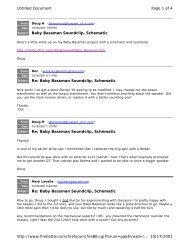
<strong>Mods</strong> to the Tube board<br />
Replace C1 cap and R5resistor to tone down the harshness of the OD Channel. Replace R41 cap to increase<br />
gain of driver stages (only if you converted boost switch to shift switch as described above).<br />
Further down the OD channel circuit, the .001uf coupling cap (C2) between V2A and V2B is followed<br />
by a 470k resistor (R5) paralleled with a 470pf cap (C1), which make up an RC network. I recommend<br />
replacing C1 with a 390pf silver mica cap and R5 with a 390k resistor. With the other mods outlined here,<br />
those values give a tone which is bright enough for blues, yet has a stronger bottom end; the bass and treble<br />
controls work well to fine-tune your sound with these values.<br />
For a stronger and fuller OD sound, you can also replace the .001uf coupling cap (C2) with a .01uf /<br />
600v Orange Drop cap. C2 is located on the middle circuit board right next to the blue channel switching<br />
relay: it is the white "rectangular box" cap. (In the Advanced <strong>Mods</strong> article, I explain how to hook up a<br />
toggle switch to select between the two values for C2: .001uf for a brighter blues tone and .01 uf for a fuller<br />
OD tone.)<br />
C1 is the tubular cap between the V2 tube socket and the middle circuit board; there is a group of 2<br />
resistors and 1 tubular cap next to the threaded post. R5 is the resistor between C1 and the threaded post. To<br />
desolder them you will need to remove the 3 black phillips machine screws that hold the circuit board to the<br />
angle bracket. <strong>The</strong>re is very little clearance for a mica cap here so you will need to bend it over the resistor<br />
R5. Although I replaced C1 with a 390pf one for a tone bright enough for blues, you may want to<br />
experiment with different values here. A 560pf cap with 470k resistor was mentioned in one post as having<br />
an almost magical effect in guitar amps, but I didn't think it worked that well in the <strong>Classic</strong> <strong>30</strong>. For a thicker<br />
tone for rock, you can drop C1 to 100-250pf, or increase it to 680-820pf for a different effect; a lower value<br />
for R5 will also produce a louder, thicker sound. In my experiments I replaced these two parts so many<br />
times that the copper traces on the circuit board wore out (I used 24 ga bus wire to make the connections).<br />
<strong>The</strong>re is one other mod I recommend if you chose to replace the .047uf boost cap with a 750pf shift cap
(thus eliminating the very strong gain boost of that switch). You can make up for the gain lost in that mod<br />
by replacing the 100K plate resistor (R41) for V3A with a higher value (120K to 150K). I put in the 150K<br />
resistor for the maximum increase in gain, but you need to use some discretion here: if you plug your guitar<br />
into a stomp box that adds plenty of gain to the signal, you may blow out one of the internal fuses if you<br />
crank the volumes up to 12. If you have little control over the guitarists using the amp, you may want to put<br />
in a 120K resistor which increases the gain of the driver circuit less than the 150K resistor. <strong>The</strong>re is a<br />
tradeoff involved here: although the gain of the stage is increased, its headroom is decreased so if you are<br />
looking for a strong, clean Normal tone you may want to skip this mod.<br />
Here is the diagram for the 3 mods on the Tube Board:<br />
Final notes on these mods<br />
Tips to reduce buzzing and rattles with increased low frequency response.<br />
After replacing the tone caps as outlined above, I found my amp cabinet and chassis buzzing a lot<br />
because it simply wasn't designed for the fuller bass response. <strong>The</strong> chromed chassis is a lot lighter than those<br />
used in the older Fender amps so to reduce its buzzing, I glued weather-stripping along each of the sides that<br />
was secured to the cabinet. I used an open cell weatherstripping (1/2" wide by 7/16" thick) so that it could<br />
be compressed enough so that the 8 shoulder screws would still line up. For the top with the controls I cut<br />
the weatherstripping down so that its width and thickness was 1/4". Self-stick weatherstripping tends to peel<br />
off shiny metal very easily so I ran small beads of crazy glue on the chassis. I also noticed the pilot light<br />
buzzing so I put a bead of silicon around the light housing underneath the panel.<br />
To further reduce any chassis buzzing or rattles, you could also try gluing small o-rings to the 8 threaded<br />
posts which secure the circuit board with the tube sockets. I used 5-minute Epoxy in the "hypo" tube along<br />
to glue the Perfect Match #14504P o-rings (9/32"x5/32"x1/16"). <strong>The</strong>se o-rings tend to fall off when you take
the amp apart so I wouldn't recommend adding them until you are completely satisfied with the amp mods.<br />
[If you try adding these o-rings, wait overnight for the glue dry. I didn't and one of the screws broke off<br />
inside which was a real hassle to fix. After that when the o-rings fell off I just left them off, although I may<br />
add them all back someday.] <strong>The</strong>re is a tendency for the chassis bottom to vibrate at high volume levels; I<br />
may glue a piece of reinforced neoprene parallel to the tube sockets to reduce these vibrations. [In the<br />
Advanced <strong>Mods</strong>, I added pots and switches behind the tubes so you may want to skip this suggestion as<br />
well.]<br />
Another solution might be to add a jack for the built-in speaker so that you could unplug it and use an<br />
external speaker when you need to crank the amp up loud. I drilled a hole below the power switch and<br />
indicator light for a speaker jack (connect the yellow wire to the hot terminal and the blue wire to the ground<br />
terminal). <strong>The</strong> added jack is connected to the 16 ohm tap, the existing jack is connected to the 8 ohm tap,<br />
and if you plug into both jacks, they are connected in parallel to the 8 ohm tap. This last mods makes the<br />
amp much more versatile.<br />
I strongly recommend that you replace the stock 12" 16 ohm speaker. (I put in an 8 ohm Celestion V12-<br />
60 "Silver Series" for about $60 and was fairly pleased with the performance.) What I did notice when I put<br />
the stock speaker back in, the amp sounds much more alive if I plug it into the existing "Extension Speaker"<br />
jack (which uses the 8 ohm tap). I also noticed a similar response when testing the amp with the 16 ohm<br />
load of my <strong>Classic</strong> 50-410 speakers. I suspect that putting the speaker load on the 8 ohm tap has an effect on<br />
the feedback loop; in any event, for a nice blues lead guitar tone use the 8 ohm jack whenever feasible.<br />
<strong>The</strong>re is a simple trick to switch the built-in speaker from the 16 ohm tap to the 8 ohm tap: plug a bare<br />
1/4" plug into the Extension Speaker jack. <strong>The</strong> internal switching contacts of the jack will connect the builtin<br />
speaker in parallel to the 8 ohm tap when anything is plugged into the Extension Speaker jack. If you<br />
can't afford to replace the stock speaker at this time, be sure to switch it over to the 8 ohm tap.<br />
In Conclusion<br />
Legal disclaimers, suggestions and parting comments.<br />
In conclusion I thought I better issue any appropriate disclaimers. <strong>The</strong>se mods are not endorsed by <strong>Peavy</strong><br />
and will obviously void any warranty on your <strong>Peavy</strong> <strong>Classic</strong> <strong>30</strong>. <strong>The</strong> values of caps and resistors I<br />
recommend reflect my own tastes, but you are welcome to try other values. For the boost/shift cap, I like<br />
750pf because it does not drastically change the tone; a higher value such as 1000-1500pf alters the tone<br />
more, but may be more appropriate for highly distorted sounds. For the tone caps, you may want to stick<br />
with the original values (.022uf for bass and midrange), but I'd definitely recommend putting in a higher<br />
quality cap than the tan globs that <strong>Peavy</strong> uses. Many people consider the Sprague-style Orange Drop caps to<br />
be the best, although other metallized polypropylene caps work well, too.<br />
For the OD channel input mod, you may want to try a cap larger than the 680pf to 820pf cap I<br />
recommend, and you may want to try paralleling it with a 1.0M+ resistor to increase the low frequencies. As<br />
for the mods to the tube board, you can replace the 390pf silver mica cap I recommend with a 100-250pf or<br />
680-820pf for a more "midrangy" sound perhaps more suitable for modern rock. As for replacing the V3A<br />
plate load resistor R41 (100k) with a 120k or 150k resistor to increase the gain of the driver stages, this is<br />
only to compensate for the loss in gain when converting the boost switch to a shift switch; if you choose to<br />
use the 150k resistor, use discretion when turning up the volume pots.<br />
<strong>The</strong> <strong>Classic</strong> <strong>30</strong> isn't the easiest amp to work on with its printed circuit board design, but with these mods<br />
as a starting point you may be able to fine-tune your amp to get the sounds you are looking for. Good luck.
Parts List:<br />
Ref # Stock Value Modified Value (Substitute) Source / Number<br />
C4 470pf /50v tubular cer cap 680pf / 500v mica cap<br />
C7 470pf /50v tubular cer cap 390pf / 500v mica cap<br />
C2 .001uf / 6<strong>30</strong> v .01uf / 600v Orange Drop<br />
C1 470pf /50v tubular cer cap 390pf / 500v mica cap<br />
Steve Ahola<br />
March 6, 1998<br />
(Revised 3/14/98)<br />
steve_ahola@yahoo.com<br />
http://www.blueguitar.org/<br />
AES # C-SM680<br />
ME # 5982-19-500V680<br />
AES # C-SM390<br />
ME # 5982-15-500V390<br />
TE / ME # 75-715P600V0.01<br />
AES # C-UD01-6<strong>30</strong> [NOT O.D.]<br />
AES # C-SM390<br />
ME # 5982-15-500V390<br />
R5 470k 1/4 watt resistor 390k 1/4 watt resistor Radio Shack, local parts house<br />
C11 (Boost) .047uf / 50v cap 750pf (820pf) / 500v mica cap<br />
AES # C-SM820<br />
ME # 5982-19-500V820<br />
R12 220k 1/4 watt resistor 1.5M to 2.2M 1/4 watt resistor Radio Shack, local parts house<br />
C14 (Treble) 270pf /50v tubular cer cap 270pf (250pf) / 500v mica cap<br />
C18 (Bass) .022uf / 50v mon cap .047uf * (.022uf)/600v Orange Drop<br />
C19 (Mid) .022uf / 50v mon cap .022uf / 600v Orange Drop<br />
AES # C-SM250<br />
ME # 5982-15-500V270<br />
TE / ME# 75-715P600V0.047<br />
AES # C-UD047-6<strong>30</strong> [NOT OD]<br />
TE / ME# 75-715P600V0.022<br />
AES # C-UD022-6<strong>30</strong> [NOT OD]<br />
R41 100k 1/4 watt resistor 120k - 150k 1/4 watt res. Radio Shack, local parts house<br />
Parts Suppliers:<br />
* use .047uf for more bass<br />
Name Phone Fax URL http://<br />
ME: Mouser Electronics 1-800-346-6873 Call toll-free # www.mouser.com<br />
TE: Torres Engineering 1-650-571-6887 1-650-571-0849 www.wwsites.com/ca/torres007<br />
AES: Antique Electronic Supply 1-602-820-5411 www.tubesandmore.com<br />
<strong>Peavy</strong> Electronics 1-601-483-5365 1-601-486-1361 www.peavey.com<br />
Other <strong>Classic</strong> <strong>30</strong> files:<br />
● Adobe Acrobat PDF file:<br />
❍ All Seven <strong>Classic</strong> <strong>30</strong> Articles (PDF): c<strong>30</strong>_mods.pdf (804K)<br />
● Resources:<br />
❍ <strong>Classic</strong> <strong>30</strong> Schematic: c<strong>30</strong>schem.gif (116K)<br />
❍ <strong>Classic</strong> <strong>30</strong> Schematic (w/ <strong>Mods</strong>): c<strong>30</strong>scmod.gif (144K)<br />
❍ <strong>Classic</strong> <strong>30</strong> Layout (hi-res): c<strong>30</strong>layg1.jpg (708K)<br />
Back to my Tube Amp Page<br />
Back to my Home Page