

Il transceiver XTR-903-A rappresenta una soluzione semplice ed ...
Il transceiver XTR-903-A rappresenta una soluzione semplice ed ...
Il transceiver XTR-903-A rappresenta una soluzione semplice ed ...

Create successful ePaper yourself
Turn your PDF publications into a flip-book with our unique Google optimized e-Paper software.
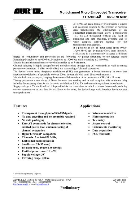
Multichannel Micro Emb<strong>ed</strong>d<strong>ed</strong> Transceiver<br />
<strong>XTR</strong>-<strong>903</strong>-A8 868-870 MHz<br />
<strong>XTR</strong>-<strong>903</strong>-A8 radio <strong>transceiver</strong> represents a simple<br />
and economic solution to the problem of wireless<br />
data transmission: the employment of an<br />
emb<strong>ed</strong>d<strong>ed</strong> microprocessor allows a transparent<br />
TTL RS-232 throughput without any ne<strong>ed</strong> of<br />
packaging and data encoding, avoiding user to<br />
write complex software routines for the<br />
transmission management.<br />
It’s possible to set up input serial spe<strong>ed</strong> (9600-<br />
19200-38400 bps) by means of two input lines (SP1<br />
e SP2) and it is automatically assign<strong>ed</strong> a different<br />
degree of r<strong>ed</strong>undancy and protection on the forward<strong>ed</strong> RF packet depending on the select<strong>ed</strong> spe<strong>ed</strong>:<br />
Hamming+Manchester at 9600 bps, Manchester at 19200 bps and Scrambling at 38400 bps.<br />
Module is a multichannel <strong>transceiver</strong> which enables up to 7 channels.<br />
Channel selecting is highly straightforward and takes place through easy AT commands, as well as emitt<strong>ed</strong><br />
power selection (from –8 dBm to +10 dBm) and monitoring of channel occupation.<br />
The device works using frequency modulation (FSK) that guarantees a better immunity to noise than<br />
amplitude modulation: it’s possible to cover 200 m in open air with omni directional antennas.<br />
Module looks very compact, keeping the same small dimensions of its pr<strong>ed</strong>ecessor <strong>XTR</strong> (33 x 23 mm).<br />
Timing guarantees a max delay of 20 ms between data sending and its real reception: this minimum delay<br />
includes the necessary time for the device to switch from RX to TX and transmit a synchronization header.<br />
Supply voltage is 3V stabiliz<strong>ed</strong> and it is provid<strong>ed</strong> for the <strong>transceiver</strong> to switch to power down mode, r<strong>ed</strong>ucing<br />
current consumption to less than 10 µA. Even in that state, the device keeps valid interface levels towards<br />
user application.<br />
Features Applications<br />
• Transparent throughput of RS-232signals • Wireless hands free<br />
• No data encoding and no preamble requir<strong>ed</strong> • Home automation<br />
• No data packaging • Telemetry<br />
• Easy AT commands for channel selection, • Access control<br />
emitt<strong>ed</strong> power level and monitoring of • Instruments monitoring<br />
channel occupation • Data acquisition<br />
• HyperTerminal* compatible • POS terminals<br />
• Channels: 7 at 868-870 MHz,<br />
• Emb<strong>ed</strong>d<strong>ed</strong> microprocessor<br />
• Small size ( 23x33 mm )<br />
• Bit rate: 9600, 19200 o 38400 bps<br />
• Emitt<strong>ed</strong> power: max 10 mW<br />
• Supply voltage: 3V<br />
• Covering range: 200 m<br />
* Trademark register<strong>ed</strong> by Hilgraeve<br />
AUR°EL S.p.A. Via Foro dei Tigli, 4 - 47015 Modigliana (FC) – ITALY July 25th, 2003<br />
Tel.: +390546941124 – Fax: +390546941660 Pag 1 di 18<br />
http://www.aurel.it - email: lab-el@aurel.it<br />
Preliminary
Pin Description<br />
RF GND – pin 1,3<br />
ANT – pin 2<br />
Multichannel Micro Emb<strong>ed</strong>d<strong>ed</strong> Transceiver<br />
<strong>XTR</strong>-<strong>903</strong>-A8 868-870 MHz<br />
1 18<br />
Pin No. Nome Pin<br />
2<br />
3<br />
17<br />
16<br />
Pin 1-3<br />
Pin 2<br />
Pin 9-10-18<br />
RF GND<br />
ANT<br />
GND<br />
<strong>XTR</strong>-<strong>903</strong>-A8<br />
15<br />
14<br />
Pin 11<br />
Pin 12<br />
SP1<br />
RSRX<br />
13<br />
12<br />
Pin 13<br />
Pin 14<br />
Pin 15<br />
485EN<br />
RSTX<br />
SP2<br />
11<br />
Pin 16 PWRDN<br />
9<br />
10<br />
Pin 17 Vcc<br />
RF ground plane connection.<br />
Antenna terminal, 50 ohm imp<strong>ed</strong>ance.<br />
GND – pin 9,10,18<br />
Ground (0V).<br />
SP1, SP2 – pin 11,15<br />
These pins allow selection of input/output serial data spe<strong>ed</strong>.. Setting up them, it is possible<br />
to select one of the three enabl<strong>ed</strong> spe<strong>ed</strong>, from 9600 bps to 38400 bps. Table 1 illustrates how<br />
to set up the desir<strong>ed</strong> value:<br />
SP1 SP2 Spe<strong>ed</strong><br />
GND Vcc 9600<br />
Vcc Vcc 19200<br />
Vcc GND 38400<br />
Table 1 – Set up of serial data spe<strong>ed</strong><br />
AUR°EL S.p.A. Via Foro dei Tigli, 4 - 47015 Modigliana (FC) – ITALY July 25th, 2003<br />
Tel.: +390546941124 – Fax: +390546941660 Pag 2 di 18<br />
http://www.aurel.it - email: lab-el@aurel.it<br />
Preliminary
Multichannel Micro Emb<strong>ed</strong>d<strong>ed</strong> Transceiver<br />
<strong>XTR</strong>-<strong>903</strong>-A8 868-870 MHz<br />
A different degree of r<strong>ed</strong>undancy and protection is associat<strong>ed</strong> to the RF packet according to<br />
the select<strong>ed</strong> spe<strong>ed</strong>: this means that slower spe<strong>ed</strong> involves an higher level of reliability and/or<br />
further distances.<br />
RSRX – pin 12<br />
Data output of the receiver in TTL RS-232 logic levels with 1 start bit (0V), 8 data bits and<br />
1 stop bit (3V). Output is normally high (3V).<br />
485EN – pin 13<br />
3 V<br />
0 V<br />
START<br />
D A T A<br />
Enable pin to drive external RS-485 <strong>transceiver</strong>.<br />
RSTX – pin 14<br />
Data input to the transmitter in TTL RS-232 logic levels with 1 start bit (0V), 8 data bits and<br />
1 stop bit (3V). Input is normally high (3V).<br />
PWRDN – pin 16<br />
Vcc – pin 17<br />
Enable pin to switch on or off the power-saving feature. By supplying 3V the module moves<br />
to Power Down mode, switching off all active circuitry and r<strong>ed</strong>ucing consumption to less<br />
than 10 µA: even in that state the logical levels of input/output data lines are being kept to<br />
high levels (3V). By supplying 0V the device works in operational mode.<br />
Positive supply voltage (3V).<br />
AUR°EL S.p.A. Via Foro dei Tigli, 4 - 47015 Modigliana (FC) – ITALY July 25th, 2003<br />
Tel.: +390546941124 – Fax: +390546941660 Pag 3 di 18<br />
http://www.aurel.it - email: lab-el@aurel.it<br />
Preliminary<br />
STOP
Absolute Limits<br />
Work Temperature range -20 °C ÷ +70 °C<br />
Storage Temperature range -40 °C ÷ +100 °C<br />
Max Supply Voltage +6V<br />
Input pin Voltage -1.0 ÷ Vcc + 0.3V<br />
Output pin Voltage -1.0 ÷ Vcc + 0.3V<br />
Technical Characteristics<br />
Multichannel Micro Emb<strong>ed</strong>d<strong>ed</strong> Transceiver<br />
<strong>XTR</strong>-<strong>903</strong>-A8 868-870 MHz<br />
Min. Tip. Max. Units<br />
DC values<br />
Supply Voltage 2.7 3 3.3 V<br />
(rx mode) Current 26 mA<br />
(tx mode @ -8 dBm) Current 20 mA<br />
(tx mode @ 10 dBm) Current 31 mA<br />
(stand-by mode) Current 8 10 µA<br />
Input/output Logical 1 Level 0.7xVcc Vcc V<br />
Input/output Logical 0 Level<br />
RF<br />
0 0.3xVcc V<br />
Modulation FSK<br />
Rx Sensitivity -105 dBm<br />
Tx Max Power Output<br />
Performance<br />
-8 10 dBm<br />
Input Bit Rate 1<br />
9600, 19200 e 38400 bps<br />
Outdoor range 200 m<br />
Available Channels<br />
Timing<br />
7<br />
PWRDN → RX 7 ms<br />
PWRDN → TX 5 ms<br />
TX → RX 3 ms<br />
RX → TX 3 ms<br />
CH #X → CH #Y<br />
Default Values (NO programming)<br />
3 ms<br />
2<br />
Channel frequency 868.88 MHz<br />
Tx Output Power 4 dBm<br />
1 Input signal is made of 1 start bit, 8 data bits and 1 stop bit, no parity.<br />
AUR°EL S.p.A. Via Foro dei Tigli, 4 - 47015 Modigliana (FC) – ITALY July 25th, 2003<br />
Tel.: +390546941124 – Fax: +390546941660 Pag 4 di 18<br />
http://www.aurel.it - email: lab-el@aurel.it<br />
Preliminary
2 Default values are intend<strong>ed</strong> as available with no ne<strong>ed</strong> of AT commands.<br />
Usage Conditions<br />
Multichannel Micro Emb<strong>ed</strong>d<strong>ed</strong> Transceiver<br />
<strong>XTR</strong>-<strong>903</strong>-A8 868-870 MHz<br />
Implementation of an emb<strong>ed</strong>d<strong>ed</strong> powerful microprocessor spares to user the trouble of<br />
implementing a synchronization protocol between the sending and receiving unit, thus significantly<br />
r<strong>ed</strong>ucing the design cycle times of any system that requires RF data transfer.<br />
The <strong>XTR</strong>-<strong>903</strong>-A8 <strong>transceiver</strong> allows the transfer of data in RS232-TTL logic as they are coming<br />
out from a microprocessor or from a PC serial port (with electrical level conversion), with no ne<strong>ed</strong><br />
of any further coding. In this way the radio transmission will be completely transparent, allowing<br />
the radio transfer of data packets of any length* and with a time shift not longer then 20 ms between<br />
the data delivery and the actual reception: this time is ne<strong>ed</strong><strong>ed</strong> to "open" the connection and, then,<br />
the data transfer is carri<strong>ed</strong> on at the real serial port spe<strong>ed</strong> (9600, 19200 or 38400 bps).<br />
RS-232 RF RS-232<br />
TXD A<br />
RXD A<br />
A<br />
<strong>XTR</strong><br />
<strong>903</strong><br />
A4<br />
RF OUT A RF OUT B<br />
Fig.1 – Two <strong>XTR</strong>-<strong>903</strong>-A8's in connection.<br />
<strong>XTR</strong>-<strong>903</strong>-A8 status can be summariz<strong>ed</strong> as follows:<br />
• Idle mode<br />
• Transmit mode<br />
• Receive mode<br />
• Command mode<br />
• Power Down mode<br />
*Max input packet length is dependant from signal precision of bit rate. Typically it results higher than 16KBytes<br />
B<br />
<strong>XTR</strong><br />
<strong>903</strong><br />
A4<br />
RXD B<br />
TXD B<br />
AUR°EL S.p.A. Via Foro dei Tigli, 4 - 47015 Modigliana (FC) – ITALY July 25th, 2003<br />
Tel.: +390546941124 – Fax: +390546941660 Pag 5 di 18<br />
http://www.aurel.it - email: lab-el@aurel.it<br />
Preliminary
Idle mode<br />
Power<br />
Down<br />
Mode<br />
Multichannel Micro Emb<strong>ed</strong>d<strong>ed</strong> Transceiver<br />
<strong>XTR</strong>-<strong>903</strong>-A8 868-870 MHz<br />
Transmit<br />
Mode<br />
Idle<br />
Mode<br />
Command<br />
Mode<br />
Receive<br />
Mode<br />
This is the rest status of the <strong>transceiver</strong>, as soon as it is turn<strong>ed</strong> on: in this mode the <strong>transceiver</strong> will<br />
be "listening" for everything is present in radio frequency, waiting for both RF synchronization<br />
sequence or data presence on the serial line input. If any of the two occurrence will happen, the<br />
<strong>transceiver</strong> will leave Idle mode, switching to the new proper status.<br />
Transmit mode<br />
From the resting status of Idle mode, the <strong>transceiver</strong> will automatically go to transmission status<br />
(Transmit mode) as soon as on the serial data input line (pin 14) a start bit is sens<strong>ed</strong>.<br />
RF data transfer is transparent to user, and the data packet will be deliver<strong>ed</strong> without any buffering,<br />
with no limit on packet length. No checksum or CRC is foreseen: the responsibility to properly<br />
handle discrimination between well receiv<strong>ed</strong> packets and possible corrupt<strong>ed</strong> data packets is left to<br />
User.<br />
AUR°EL S.p.A. Via Foro dei Tigli, 4 - 47015 Modigliana (FC) – ITALY July 25th, 2003<br />
Tel.: +390546941124 – Fax: +390546941660 Pag 6 di 18<br />
http://www.aurel.it - email: lab-el@aurel.it<br />
Preliminary
TXD A<br />
RF OUT<br />
A<br />
RXD B<br />
0 20<br />
Data Bytes<br />
Preamble<br />
Code Data<br />
Closing Bytes<br />
Multichannel Micro Emb<strong>ed</strong>d<strong>ed</strong> Transceiver<br />
<strong>XTR</strong>-<strong>903</strong>-A8 868-870 MHz<br />
(ms)<br />
Fig. 3 – Timing Diagram of a data packet transmission<br />
As shown in above Timing Diagram (Fig. 3), from the starting time (0 time), when the first data<br />
start to flow to the sending module input, to the moment when the same first data is receiv<strong>ed</strong> on the<br />
remote unit, about 20 milliSec. are elaps<strong>ed</strong>. This delay accounts for the preamble transmission that<br />
the sending unit automatically places before to the packet of data to be sent: this is made to wake up<br />
and synchronize the receiver at the remote unit.<br />
On the other end, as a tail to the data packet a closing sequence of bytes is automatically add<strong>ed</strong> and<br />
transmitt<strong>ed</strong>.<br />
Possible data spe<strong>ed</strong> to the sending unit transmitter (TXD, pin 14), 9600 bps, 19200 bps and 38400<br />
bps, is settable via pin SP1 (pin 11) and SP2 (pin 15), in accordance to Table 1.<br />
For each of the selectable serial spe<strong>ed</strong>s, a different level of r<strong>ed</strong>undancy will be add<strong>ed</strong>, while it is<br />
transmitt<strong>ed</strong> at RF. This variety can be helpful to find the best suitable configuration of the complete<br />
system according to all the possible conditions that can affect Radio Frequency propagation.<br />
Spe<strong>ed</strong> RF Data Coding<br />
38400 Any single byte of the data packet to be sent is affect<strong>ed</strong> with pseudo-random balancing.<br />
There is no assurance that data receiv<strong>ed</strong> at remote module was not corrupt<strong>ed</strong> during<br />
radio transmission.<br />
19200 Any single byte of the data packet to be sent is balanc<strong>ed</strong> with the same number of ‘0’<br />
and ‘1’ (Manchester).<br />
The system can recognize any single error per data bit and, when this is happening, will<br />
force a stop to the transfer, on the data line of the receiving unit, of the RF data.<br />
AUR°EL S.p.A. Via Foro dei Tigli, 4 - 47015 Modigliana (FC) – ITALY July 25th, 2003<br />
Tel.: +390546941124 – Fax: +390546941660 Pag 7 di 18<br />
http://www.aurel.it - email: lab-el@aurel.it<br />
Preliminary
Multichannel Micro Emb<strong>ed</strong>d<strong>ed</strong> Transceiver<br />
<strong>XTR</strong>-<strong>903</strong>-A8 868-870 MHz<br />
9600 Manchester + Hamming: Hamming code allows correction of any single error occurring<br />
in any data nibble.<br />
This is the most safe spe<strong>ed</strong> to send data, as it set the system for error detection and<br />
correction.<br />
Receive mode<br />
Table 2 – R<strong>ed</strong>undancy possibilities vs. serial data spe<strong>ed</strong><br />
Transfer from Idle to Receive mode will happen as soon as the module recognizes, on the incoming<br />
RF, the synchronization preamble. From this point the <strong>transceiver</strong> will stay in Receive mode up to<br />
the reception of packet closing sequence.<br />
Any data in input from the serial line will be discard<strong>ed</strong> while the module is in Receive mode.<br />
Command mode<br />
Command mode allows User to configure the main parameters to change the device work<br />
conditions, such as parameters to select a new work channel or to set emitt<strong>ed</strong> RF power to desir<strong>ed</strong><br />
value. This allows a high flexibility degree to personalize design and application.<br />
Programming is carri<strong>ed</strong> out via simple AT commands. To force Command mode, from Idle mode,<br />
the following string must be sent via serial line<br />
• 3 ASCII characters imm<strong>ed</strong>iately follow<strong>ed</strong> from 3 plus charact. (+++)<br />
The module will answer with OK string to confirm its new setting in Command mode (<br />
is intend<strong>ed</strong> as ASCII 10, Carriage Return).<br />
Registers available for programming, where the parameters are stor<strong>ed</strong>, are 16 (from 1 to 16), some<br />
of them are available only for read operations, others will be read/write.<br />
Syntax to read a valu<strong>ed</strong> stor<strong>ed</strong> in a register is as follows:<br />
ATSx (x= 1, ..., 16)<br />
Assuming that the command was correctly issu<strong>ed</strong>, answer to this command is the value of the<br />
content of the register. For a command issu<strong>ed</strong> with errors, answer is given back as: ERROR.<br />
To change the value of parameter in a register, the following syntax is us<strong>ed</strong>:<br />
ATSx=Y (x= 1, ..., 16) , Y= value to be insert<strong>ed</strong><br />
with a back answer made of the string OK if command was correctly perform<strong>ed</strong>, or<br />
ERROR if a syntax error was made or if the value that was enter<strong>ed</strong> to be written is<br />
<strong>una</strong>cceptable as parameter for that register.<br />
All the values written into registers are temporary valid and will be lost when the module will be<br />
turn<strong>ed</strong> off ( Power voltage remov<strong>ed</strong>), unless they were previously forc<strong>ed</strong> sav<strong>ed</strong> into the EEPROM<br />
memory available in the emb<strong>ed</strong>d<strong>ed</strong> microprocessor : only in this case, the modifi<strong>ed</strong> values will be<br />
still active when the module will be turn<strong>ed</strong> again on.<br />
The command to force saving off ALL the values in register is:<br />
AUR°EL S.p.A. Via Foro dei Tigli, 4 - 47015 Modigliana (FC) – ITALY July 25th, 2003<br />
Tel.: +390546941124 – Fax: +390546941660 Pag 8 di 18<br />
http://www.aurel.it - email: lab-el@aurel.it<br />
Preliminary
ATWR<br />
Multichannel Micro Emb<strong>ed</strong>d<strong>ed</strong> Transceiver<br />
<strong>XTR</strong>-<strong>903</strong>-A8 868-870 MHz<br />
To exit Command Mode, going back to the normal operating status of <strong>transceiver</strong>, the command to<br />
be issu<strong>ed</strong> is:<br />
ATCC<br />
When in Command mode, it is possible to concatenate more instructions in one command line,<br />
separating each command by comma (,) operator. With following command line, for example,<br />
register 3 is set to value 2, the change is permanently sav<strong>ed</strong> and the Command Mode is left:<br />
Example: ats3=2,wr,cc<br />
OK<br />
As shown above, the prefix -at- is just us<strong>ed</strong> once in the first command of line, while is not us<strong>ed</strong> for<br />
the following ones.<br />
Command chaining is possible only for write operations, while it will receive an error answer if<br />
us<strong>ed</strong> in read operations.<br />
Example: ats1,cc<br />
ERROR<br />
Commands are not case sensitive, so there is not problem to use both capital and small letters.<br />
To have meaning of each register and the possible configuration values, please see Appendix A.<br />
Power Down mode<br />
Setting to high value (+3V) pin 16 (PWRDN), the <strong>transceiver</strong> will fall in a power saving mode,<br />
limiting its consumption to less than 10 µA: in this mode the <strong>transceiver</strong> is not in a condition to<br />
receive or transmit: to bring it back to an operating status (Idle Mode), pin 16 must be forc<strong>ed</strong> again<br />
to low voltage value (0V).<br />
Also with most of circuits not under power, even when in Power Down Mode, the module will<br />
keep to the outside word interface lines at logical consistent values: for example, the receiv<strong>ed</strong> data<br />
line (RXD) will keep the high logical value (+3V) associat<strong>ed</strong> to stop bit.<br />
AUR°EL S.p.A. Via Foro dei Tigli, 4 - 47015 Modigliana (FC) – ITALY July 25th, 2003<br />
Tel.: +390546941124 – Fax: +390546941660 Pag 9 di 18<br />
http://www.aurel.it - email: lab-el@aurel.it<br />
Preliminary
Applications<br />
Multichannel Micro Emb<strong>ed</strong>d<strong>ed</strong> Transceiver<br />
<strong>XTR</strong>-<strong>903</strong>-A8 868-870 MHz<br />
Fig.3 shows a typical <strong>XTR</strong>-<strong>903</strong>-A8 application, with the <strong>transceiver</strong> connect<strong>ed</strong> to a microprocessor<br />
that, in addition to data reception and transmission on the input and output lines (TXD e RXD), is<br />
also controlling two lines d<strong>ed</strong>icat<strong>ed</strong> to serial interface spe<strong>ed</strong> selection (SP1 e SP2) plus PWRDN<br />
line.<br />
1 RF GND<br />
2 ANT<br />
9 GND<br />
GND 18<br />
Vcc 17<br />
3 RF GND PWRDN 16<br />
RXD 12<br />
SP1 11<br />
GND 10<br />
+ 3V<br />
OUT PORT<br />
SP2 15 OUT PORT<br />
TXD 14<br />
OUT PORT<br />
IN PORT<br />
OUT PORT<br />
<strong>XTR</strong>-<strong>903</strong>-A8 Microcontroller<br />
Fig.3 – Example of connection between <strong>XTR</strong>-<strong>903</strong>-A8 and microcontroller.<br />
AUR°EL S.p.A. Via Foro dei Tigli, 4 - 47015 Modigliana (FC) – ITALY July 25th, 2003<br />
Tel.: +390546941124 – Fax: +390546941660 Pag 10 di 18<br />
http://www.aurel.it - email: lab-el@aurel.it<br />
Preliminary
Multichannel Micro Emb<strong>ed</strong>d<strong>ed</strong> Transceiver<br />
<strong>XTR</strong>-<strong>903</strong>-A8 868-870 MHz<br />
In Fig.4, a sample connection between <strong>XTR</strong>-<strong>903</strong>-A8 module and PC serial port is shown: The<br />
integrate component between the <strong>transceiver</strong> and the RS232 port is only us<strong>ed</strong> to convert the<br />
electrical level voltages from RS-232 and TTL logic.<br />
Working with the RTS line (pin 7 of DB9 connector) it is possible to drive the PWRDN line, while<br />
the serial data spe<strong>ed</strong> selection is set to 19200 bps.<br />
1 RF GND GND 18<br />
2 ANT<br />
Vcc 17<br />
+ 3V<br />
5<br />
3 RF GND PWRDN 16 R2OUT 9<br />
SP2 15<br />
TXD 14 R1OUT<br />
R1IN<br />
R2IN<br />
RXD 12 T2IN T2OUT<br />
SP1 11<br />
9 GND GND 10<br />
<strong>XTR</strong>-<strong>903</strong>-A8 MAX-232 DB9<br />
Fig.4 – Example of connection <strong>XTR</strong>-<strong>903</strong>-A8 and RS-232 serial port at 19200 bps.<br />
AUR°EL S.p.A. Via Foro dei Tigli, 4 - 47015 Modigliana (FC) – ITALY July 25th, 2003<br />
Tel.: +390546941124 – Fax: +390546941660 Pag 11 di 18<br />
http://www.aurel.it - email: lab-el@aurel.it<br />
Preliminary<br />
1<br />
6
Usage suggestions<br />
Multichannel Micro Emb<strong>ed</strong>d<strong>ed</strong> Transceiver<br />
<strong>XTR</strong>-<strong>903</strong>-A8 868-870 MHz<br />
Ground circuitry<br />
1. Must cover all area around the module. Circuit should be etch<strong>ed</strong> on two side PCB, with sides<br />
connect<strong>ed</strong> every 15 mm (at least)<br />
2. Ground must be present around the antenna output area<br />
50 Ohm lines (connection between pin 2 and Antenna):<br />
1. Should be as short as possible<br />
2. Wide 1.8 mm for FR4 PCBs (1 mm thick) and 2.9 mm for FR6 (1.6 mm thick). Distance from<br />
surrounding GND is more than 1 mm (2 mm is better).<br />
3. On reverse side of PCB, should have a rather large GND area<br />
Antenna connection:<br />
1. Can be us<strong>ed</strong> to directly connect a radiating stylus (85 mm straight wire)<br />
2. Can be us<strong>ed</strong> to connect the central conductor of a coaxial cable to remote antenna. The cable out<br />
braid must be connect<strong>ed</strong> to GND near the antenna connection.<br />
Antenna:<br />
1. At <strong>transceiver</strong> antenna pin a proper antenna must be connect<strong>ed</strong>: a 8.5 cm stylus is suggest<strong>ed</strong>,<br />
made of copper or brass of 1 mm diameter. the body of the antenna must be as straight as<br />
possible and should be free from any other circuit or metallic body ( at least 5 cm are suggest<strong>ed</strong>)<br />
Antenna can be us<strong>ed</strong> both vertically or horizontally, with suggestion to use a lot of ground<br />
circuit around the fe<strong>ed</strong> connection point.<br />
Note: as an alternative to a. m. antennas, any of the antenna propos<strong>ed</strong> from AUREL can be us<strong>ed</strong>.<br />
Please see Data Sheets and Application Notes).<br />
Usage of antennas different from the suggest<strong>ed</strong> ones do not guaranty the adherence to CE<br />
Homologation measurements.<br />
Other components:<br />
AUR°EL S.p.A. Via Foro dei Tigli, 4 - 47015 Modigliana (FC) – ITALY July 25th, 2003<br />
Tel.: +390546941124 – Fax: +390546941660 Pag 12 di 18<br />
http://www.aurel.it - email: lab-el@aurel.it<br />
Preliminary
Multichannel Micro Emb<strong>ed</strong>d<strong>ed</strong> Transceiver<br />
<strong>XTR</strong>-<strong>903</strong>-A8 868-870 MHz<br />
1. Keep AUREL module as far as possible from other circuit components (min. 5 mm)<br />
2. Keep as far as possible microprocessor and clock circuitry. Apply GND shields<br />
3. Do not install components around the 50 Ohm line(s). Keep at least 10 mm clearance<br />
4. If antenna is directly connect<strong>ed</strong> to PCB antenna connection point (see above) keep a 50 mm<br />
radius area with no components, but adequate GND. If antenna connection point is us<strong>ed</strong> for<br />
coax cable connection, it is possible to move components up to 5 mm.<br />
Reference Rules<br />
The <strong>XTR</strong>-<strong>903</strong>-A8 <strong>transceiver</strong> is EC certifi<strong>ed</strong> and in particular it complies with the European Rules<br />
EN 300 220-3 and EN 301 489. The product has been test<strong>ed</strong> according to rule EN 60950 and it can<br />
be utiliz<strong>ed</strong> inside a special insulat<strong>ed</strong> housing that assures the compliance with the above mention<strong>ed</strong><br />
rule. The <strong>transceiver</strong> must be suppli<strong>ed</strong> by a very low voltage safety source, protect<strong>ed</strong> against short<br />
circuits.<br />
The use of the <strong>transceiver</strong> module is foreseen inside housings that assure the overcoming of the rule<br />
EN 61000-4-2 not directly applicable to the module itself. In particular, it is at the user’ s care the<br />
insulation of the external antenna connection and of the antenna itself, since the RF output of the<br />
<strong>transceiver</strong> is not built to directly bear the electrostatic charges foreseen by the a.m. rule.<br />
CEPT 70-03 Recommendations<br />
In order to comply with such rule, the device (strictly for what it concerns the transmission phase)<br />
must be us<strong>ed</strong> only for a 1% of an hourly duty-cycle (that means 0.6 minutes of utilization over 60)<br />
for channels 0, 1 and 2.<br />
Max admitt<strong>ed</strong> duty cycle is 0.1% for channels 4, 5 and 6.<br />
Only for channel eleven a full 100% duty cycle is allow<strong>ed</strong>.<br />
AUR°EL S.p.A. Via Foro dei Tigli, 4 - 47015 Modigliana (FC) – ITALY July 25th, 2003<br />
Tel.: +390546941124 – Fax: +390546941660 Pag 13 di 18<br />
http://www.aurel.it - email: lab-el@aurel.it<br />
Preliminary
Mechanical dimensions<br />
23 mm<br />
Multichannel Micro Emb<strong>ed</strong>d<strong>ed</strong> Transceiver<br />
<strong>XTR</strong>-<strong>903</strong>-A8 868-870 MHz<br />
1<br />
2<br />
3<br />
9<br />
30,47 mm<br />
<strong>XTR</strong>-<strong>903</strong>-A8<br />
33 mm<br />
Pin Spacing 2,54 mm<br />
18<br />
17<br />
16<br />
15<br />
14<br />
13<br />
12<br />
11<br />
10<br />
Fig.5 – Micro Emb<strong>ed</strong>d<strong>ed</strong> Transceiver.<br />
AUR°EL S.p.A. Via Foro dei Tigli, 4 - 47015 Modigliana (FC) – ITALY July 25th, 2003<br />
Tel.: +390546941124 – Fax: +390546941660 Pag 14 di 18<br />
http://www.aurel.it - email: lab-el@aurel.it<br />
Preliminary
Appendix A – Register Programming<br />
Multichannel Micro Emb<strong>ed</strong>d<strong>ed</strong> Transceiver<br />
<strong>XTR</strong>-<strong>903</strong>-A8 868-870 MHz<br />
Different work performances of the <strong>transceiver</strong>, such as RF channel selection, RF emitt<strong>ed</strong> power,<br />
etc..., can be programm<strong>ed</strong> from User with setting of special parameters: this will be made by<br />
programming 16 available registers. Following are the meaning and the programming possibilities<br />
for each register.<br />
At this very moment, only 4 out of 16 registers are us<strong>ed</strong> and document<strong>ed</strong> (registers 1, 2, 3, 16),<br />
While the remaining will be us<strong>ed</strong> for future enhancements.<br />
Register 1 - FREQUENCY BAND<br />
This register is READ ONLY and will supply info relat<strong>ed</strong> to the operational RF band us<strong>ed</strong> by<br />
<strong>transceiver</strong> (<strong>XTR</strong>-<strong>903</strong>-a is available in different models also for 433 and 915 Mhz bands).<br />
Command Values Readable (R)/ Writable (W)<br />
ATS1 0 = 433-434 MHz<br />
1 = 868-870 MHz<br />
2 = 902-928 MHz<br />
R<br />
Example 1: Module set up to operate on the 868-870 MHz band<br />
+++OK<br />
ATS1<br />
1<br />
Example 2: Syntax Error: This register is available for read only!<br />
+++OK<br />
ATS1=2<br />
ERROR<br />
AUR°EL S.p.A. Via Foro dei Tigli, 4 - 47015 Modigliana (FC) – ITALY July 25th, 2003<br />
Tel.: +390546941124 – Fax: +390546941660 Pag 15 di 18<br />
http://www.aurel.it - email: lab-el@aurel.it<br />
Preliminary
Register 2 – RF CHANNEL<br />
Multichannel Micro Emb<strong>ed</strong>d<strong>ed</strong> Transceiver<br />
<strong>XTR</strong>-<strong>903</strong>-A8 868-870 MHz<br />
This register is available for read and write operations. It allows to get fe<strong>ed</strong> backs of the RF<br />
frequency (channel) setting for both receiving and transmitting circuits. Makes it possible to "write"<br />
a different frequency (channel).<br />
Command Values Readable (R)/ Writable (W)<br />
ATS2 0 = 868.19 MHz<br />
1 = 868.34 MHz<br />
2 = 868.49 MHz<br />
4 = 868.80 MHz<br />
5 = 868.95 MHz<br />
6 = 869.11 MHz<br />
11 = 869.88 MHz<br />
R/W<br />
Example 1: Reading RF frequency (869.88 MHz)<br />
+++OK<br />
ATS2<br />
11<br />
Example 2: Selecting channel 1 as work frequency (868.34 MHz)<br />
+++OK<br />
ATS2=1<br />
OK<br />
AUR°EL S.p.A. Via Foro dei Tigli, 4 - 47015 Modigliana (FC) – ITALY July 25th, 2003<br />
Tel.: +390546941124 – Fax: +390546941660 Pag 16 di 18<br />
http://www.aurel.it - email: lab-el@aurel.it<br />
Preliminary
Register 3 – EMITTED RF POWER<br />
Multichannel Micro Emb<strong>ed</strong>d<strong>ed</strong> Transceiver<br />
<strong>XTR</strong>-<strong>903</strong>-A8 868-870 MHz<br />
This register is available for read and write operations. It allows to get fe<strong>ed</strong> backs of the RF output<br />
power emitt<strong>ed</strong> from the transmitting circuits. Makes it possible to "write" a different level of<br />
emitt<strong>ed</strong> power.<br />
Command Values Readable (R)/ Writable (W)<br />
ATS3 0 = - 8 dBm<br />
1 = - 2 dBm<br />
2 = + 4 dBm<br />
3 = + 10 dBm<br />
R/W<br />
Example 1: Reading the RF emitt<strong>ed</strong> power (-2 dBm)<br />
+++OK<br />
ATS3<br />
1<br />
Example 2: Setting emitt<strong>ed</strong> RF power to max available value (+10 dBm)<br />
+++OK<br />
ATS2=3<br />
OK<br />
Registers 4 to 15 – RESERVED FOR FUTURE ENHANCEMENTS<br />
AUR°EL S.p.A. Via Foro dei Tigli, 4 - 47015 Modigliana (FC) – ITALY July 25th, 2003<br />
Tel.: +390546941124 – Fax: +390546941660 Pag 17 di 18<br />
http://www.aurel.it - email: lab-el@aurel.it<br />
Preliminary
Register 16 – RSSI (Receiv<strong>ed</strong> Strength Signal Indicator)<br />
Multichannel Micro Emb<strong>ed</strong>d<strong>ed</strong> Transceiver<br />
<strong>XTR</strong>-<strong>903</strong>-A8 868-870 MHz<br />
The register is read only and will supply a digital value proportional to RF field Strength senses<br />
from the receiving circuitry. Possible values readable from register are 0 to 9.<br />
Command Values Readable (R)/ Writable (W)<br />
ATS16 0 = Min Field Strengh<br />
1<br />
2<br />
3<br />
4<br />
5<br />
6<br />
7<br />
8<br />
9 = Max Field Strenght<br />
R<br />
Example 1: Reading Field Strenght (Very good receiv<strong>ed</strong> signal)<br />
+++OK<br />
ATS16<br />
9<br />
Example 2: Reading Field Strength (Very poor, inexistent receiv<strong>ed</strong> signal)<br />
+++OK<br />
ATS16<br />
0<br />
Example 3: Syntax Error: register is read only!<br />
+++OK<br />
ATS16=3<br />
ERROR<br />
End of Document<br />
AUR°EL S.p.A. Via Foro dei Tigli, 4 - 47015 Modigliana (FC) – ITALY July 25th, 2003<br />
Tel.: +390546941124 – Fax: +390546941660 Pag 18 di 18<br />
http://www.aurel.it - email: lab-el@aurel.it<br />
Preliminary