series High Performance Air-Conditioning - Mitsubishi Heavy ...
series High Performance Air-Conditioning - Mitsubishi Heavy ...
series High Performance Air-Conditioning - Mitsubishi Heavy ...

Create successful ePaper yourself
Turn your PDF publications into a flip-book with our unique Google optimized e-Paper software.
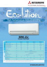
<strong>High</strong> <strong>Performance</strong> <strong>Air</strong>-<strong>Conditioning</strong><br />
FD<br />
<strong>series</strong><br />
Inverter Packaged <strong>Air</strong> Conditioners<br />
R410A<br />
Back<br />
Light<br />
Back<br />
Light
<strong>High</strong> power operation<br />
Maximum capacity<br />
operation (Max 15 minutes)<br />
• Increased compressor speed<br />
• Increased air fl ow<br />
Main functions<br />
Energy management<br />
Run / Stop<br />
Energy-saving operation<br />
• Changes set temperature at 28ºC in<br />
cooling mode and 22ºC in heating mode,<br />
25ºC in auto mode.<br />
• Operation correction by outdoor<br />
temperature<br />
Peak cut timer • Automatic temperature set back • Weekly timer • Set ON/OFF timer by hour<br />
• Set ON/OFF timer by clock • Fan only operation • Sleep timer<br />
Comfort<br />
Individual fl ap control • <strong>High</strong> power operation • External ventilation ON/OFF • Warm up operation<br />
Automatic fan speed • Temperature increment setting by 0.5ºC<br />
2 <strong>High</strong> <strong>Performance</strong> <strong>Air</strong> <strong>Conditioning</strong><br />
Simple<br />
setting by<br />
tapping<br />
button<br />
only
Advanced touch screen panel with full dot Liquid Crystal Display<br />
Basic operation<br />
All settings done by tapping touch screen panel<br />
Operation mode setting screen<br />
The operation mode can<br />
be selected by simply tapping<br />
this button.<br />
Operation mode<br />
Cooling Dry Auto Fan<br />
Heating<br />
Convenience<br />
LCD contrast setting • Back light setting • Filter clean sign • Control sound • Outdoor silent mode<br />
• Summer time setting • Home leave mode • Indoor & outdoor temperature display<br />
• Heating standby display • Defrosting operation display • Auto cooling/heating display • ºC/ºF display<br />
• Administrator settings • Room name setting<br />
Service<br />
Error code display • Operation data display • Next service data display • Contact company display<br />
• USB connection (mini-B)<br />
Setting temperature screen<br />
You can select the desired<br />
temperature by tapping the ▲▼<br />
button.<br />
Packaged <strong>Air</strong> Conditioners<br />
3
Our advanced technology has allowed us to achieve high ef�ciency, powerful heating and long<br />
distance refrigerant piping speci�cations.<br />
This feature permits installation of the units when a heating operation under temperature<br />
conditions down to -20˚C is required. Design �exibility has been improved by an extension of<br />
the refrigerant piping length to 100m (12.5 & 14.0kW).<br />
5.0 & 6.0kW<br />
7.1kW<br />
Blue<br />
Fin<br />
Micro<br />
10.0kW<br />
12.5 & 14.0kW<br />
Long piping (in case of 12.5 & 14.0kW) Strong heating (in case of 7.1~14.0kW)<br />
Piping<br />
length<br />
100m<br />
4 <strong>High</strong> <strong>Performance</strong> <strong>Air</strong> <strong>Conditioning</strong><br />
Height<br />
difference<br />
(Outdoor higher<br />
than Indoor)<br />
30m<br />
-20C<br />
-15C<br />
-20C<br />
Heating<br />
+20C<br />
-30<br />
-15C<br />
-20<br />
-10<br />
0<br />
Cooling<br />
10<br />
20<br />
30<br />
Blue<br />
Fin<br />
: Heating operation down to -20C<br />
: Nominal heating capacity maintained at -15C<br />
40<br />
+43C<br />
50
Powerful heating capacity<br />
Maximum heating capacity has been increased by optimising<br />
refrigeration control, the use of electronic expansion valves and our<br />
twin rotary compressors.<br />
The Hyper Inverter <strong>series</strong> can reach the set temperature very quickly.<br />
Normal heating capacity can be maintained when the outdoor<br />
temperature is -15°C. It is very effective for use in cold areas.<br />
(kW)<br />
18.0<br />
14.5<br />
14.0<br />
8.8<br />
0<br />
Heating capacity (in case of 12.5kW)<br />
Keeping nominal heating<br />
capacity at -15C<br />
Hyper Inverter<br />
Micro Inverter<br />
-15C 2C 7C<br />
nominal<br />
heating<br />
capacity<br />
14.0kW<br />
Micro Inverter<br />
Compact design of outdoor units<br />
FDC100VN 10.0kW<br />
Our single fan micro 10.0kW condenser is one of the most<br />
compact in the industry being only 845(h)x970(w)x370(d)<br />
Size reduction and high ef�ciency<br />
performance of the DC twin rotary<br />
compressor<br />
The DC twin rotary compressor can operate at speeds as high as 120 rps<br />
to achieve the required capacity. Vector control provides perfect<br />
compressor control. Starting current has reduced signi�cantly and<br />
vibration has been minimized.<br />
Height at 440 mm<br />
Outside diameter of shell<br />
ø185mm<br />
Former<br />
compressor<br />
Reduction in height by 22.3%<br />
Reduction in volume by 44.1%<br />
ø133mm<br />
Height at 342mm<br />
New model<br />
DC rotary compressor<br />
* Vector control:<br />
To convert the current<br />
wave to a smooth<br />
sinusoidal waveform.<br />
Temperature of supply air can reach 40C<br />
in 4 minutes after start up under low<br />
temperature operation conditions (at both<br />
indoor and outdoor temperature of 2C)<br />
and can reach 50C in 8 minutes after that.<br />
50C<br />
40C<br />
30C<br />
20C<br />
10C<br />
0C<br />
Heating capacity<br />
Hyper Inverter<br />
Improved ef�ciency of the<br />
heat exchanger<br />
Protection<br />
Micro Inverter<br />
4minutes 8minutes<br />
Re-designing the �ns to a straight shape has reduced the pressure<br />
loss of the air �ow in the heat exchanger. A new surface treatment on<br />
the �ns has enhanced the frost resistance capacity compared to<br />
former models. A high speed fan motor has increased the air�ow<br />
which allows cooling capacity to be maintained even at high outdoor<br />
air temperatures.<br />
Former model Current model<br />
Improved operation of the electronic expansion valve allows for<br />
more reliable oil return and this assists to protect the<br />
compressor.<br />
Packaged <strong>Air</strong> Conditioners<br />
5
Ceiling Cassette - 4way - Indoor units<br />
FDT.FDTC<br />
Individual �ap control system<br />
Individual �ap control is available even after<br />
installation. This means that the installation area has<br />
become wider than before.<br />
Flap control system<br />
The design of the heat exchanger has<br />
changed from 2 parts to a single piece.<br />
The height of the indoor unit has been<br />
reduced signi�cantly.<br />
* RCH-E3 is not applicable to the Individual �ap control system<br />
and the Flap control system.<br />
The thinnest design<br />
The design of the heat exchanger has changed from 2 parts to 1 part, the<br />
height of indoor unit is reduced.<br />
DC fan motors are used to<br />
increase ef�ciency. Weight<br />
has been reduced and as<br />
a result the unit has<br />
become one of the most<br />
compact in the industry.<br />
Shape of heat exchanger<br />
Previous Current<br />
6 <strong>High</strong> <strong>Performance</strong> <strong>Air</strong> <strong>Conditioning</strong><br />
FDT125~140<br />
FDT71<br />
Upper<br />
position<br />
Movable<br />
range<br />
Lower<br />
position<br />
270mm<br />
246<br />
mm<br />
The outlet design has been perfected to allow suf�cient<br />
air �ow that can reach a long distance from the indoor<br />
unit.<br />
365mm<br />
298<br />
mm<br />
Previous Current<br />
18%<br />
reduction!!<br />
9%<br />
reduction!!<br />
For person who is far<br />
from the indoor unit<br />
For both persons who are<br />
feeling hot or cold<br />
Can cool both the kitchen<br />
and the guests
Duct Connected - Middle Static pressure<br />
FDUM<br />
Automatic external static pressure (E.S.P.) control<br />
By using a DC motor, the optimum air �ow volume<br />
can be achieved by this automatic control.<br />
Setting No.<br />
E.S.P.<br />
Duct<br />
No.1<br />
10Pa<br />
New<br />
FDUM<br />
No.2<br />
20Pa<br />
No.3<br />
30Pa<br />
Improved servicing<br />
Duct<br />
Ceiling<br />
Fan unit (impeller and motor) can be pulled out<br />
from the right side of the unit. Maintenance is<br />
available from the right side or from beneath.<br />
Improvement of low tap noise dB(A)<br />
Nominal cooling capacity<br />
NEW FDUM<br />
No.4<br />
40Pa<br />
No.5<br />
50Pa<br />
5.0kW<br />
26<br />
No.6<br />
60Pa<br />
Longer Duct<br />
No.7<br />
70Pa<br />
6.0kW<br />
25<br />
Keep the same<br />
air �ow volume<br />
No.8<br />
80Pa<br />
The indoor unit will recognize external static<br />
pressure automatically and keep rated air �ow<br />
volume.<br />
Maintenance<br />
hole<br />
Service<br />
space<br />
No.9<br />
90Pa<br />
7.1kW<br />
25<br />
No.10<br />
100Pa<br />
Unit<br />
E.S.P. button<br />
External static pressure can be<br />
set by E.S.P. button.<br />
10.0kW<br />
30<br />
Pipe<br />
Fan unit<br />
<strong>Air</strong> �ow sound has been reduced by a new fan and casing design.<br />
Refrigerant �ow sound was been decreased by advanced refrigerant distributor design.<br />
Indoor model name FDUM50VF FDUM60VF FDUM71VF FDUM100VF FDUM125VF FDUM140VF<br />
12.5kW<br />
30<br />
14.0kW<br />
Current FDUM 28 28 29 32 33 33<br />
Improvement -2 -3 -4 -2 -3 -3<br />
30<br />
Packaged <strong>Air</strong> Conditioners<br />
7
FDT<br />
Outline drawing (Unit:mm)<br />
Model FDT 60,71VD<br />
8 <strong>High</strong> <strong>Performance</strong> <strong>Air</strong> <strong>Conditioning</strong><br />
INDOOR UNIT<br />
CEILING CASSETTE -4way-<br />
Remote control (Option)<br />
RC-EX1A<br />
Wired<br />
RC-E5<br />
Wireless<br />
Model 100,125,140VD<br />
FDT 60/125/140VD<br />
FDT 71/100VF<br />
RCH-E3<br />
RCN-T-36W-E
Point<br />
1 Installation<br />
Detachable covers at each corner allows<br />
for easy alignment and balance.<br />
The panel does not need to be removed.<br />
Installation time is reduced.<br />
Point<br />
3 Easy checking of drain pan<br />
To check the drain pan<br />
simply remove the corner<br />
lid.<br />
FDT Series<br />
VF model may be supplied in lieu.<br />
Point<br />
2 Infrared control option<br />
For wireless control simply<br />
insert the infrared receiver<br />
kit on the corner.<br />
wireless remote control<br />
RCN-T-36W-E<br />
Point<br />
4 700mm Drain Pump<br />
Drain can be discharged<br />
upwards by 700mm from the<br />
ceiling surface. The 260mm<br />
�exible hose is supplied as<br />
standard equipment.<br />
Flexible hose<br />
FDT60ZJXVD FDT71VNXVF FDT100VNVF FDT125VNXVD FDT140VNXVD<br />
Indoor FDT60VD FDT71VF FDT100VF FDT125VD FDT140VD<br />
Outdoor SRC60ZJX-S FDC71VNX FDC100VN FDC125VNX FDC140VNX<br />
Power supply Indoor Unit 1 Phase 230V 50Hz<br />
Capacity<br />
Input<br />
Cooling T1<br />
5.6 (2.8-6.3) 7.1 (3.2-8.0) 10.0 (4.0-11.2) 12.5 (5.0-14.0) 14.0 (5.0-16.0)<br />
Heating H1 kW 6.7 (3.1-7.1) 8.0 (3.6-9.0) 11.2 (4.0-12.5) 14.0 (4.0-17.0) 16.0 (4.0-18.0)<br />
Heating H2 N/A 7.2 N/A 15.6 16<br />
Cooling T1<br />
1.52 2.04 2.76 3.28 4.19<br />
kW<br />
Heating H1 1.70 1.94 2.74 3.43 4.2<br />
EER Cooling T1 3.68 3.48 3.62 3.81 3.34<br />
COP Heating H1 3.94 4.12 4.08 4.08 3.81<br />
Sound pressure level<br />
(JIS C9612)<br />
Indoor<br />
Outdoor<br />
dB (A)<br />
P-Hi:46 Hi:33<br />
Me:31 Lo:30<br />
54<br />
P-Hi:46 Hi:35<br />
Me:33 Lo:31<br />
51<br />
P-Hi:51 Hi:40<br />
Me:37 Lo:35<br />
49<br />
P-Hi:51 Hi:42<br />
Me:40 Lo:37<br />
50<br />
P-Hi:51 Hi:43<br />
Me:41 Lo:38<br />
52<br />
Sound power level (JIS<br />
C9612)<br />
Outdoor dB(A) 64 66 70 70 72<br />
<strong>Air</strong>fl ow Indoor l/s<br />
P-Hi: 466 Hi: 300<br />
Me: 266 Lo: 233<br />
P-Hi: 466 Hi: 350<br />
Me: 316 Lo: 283<br />
P-Hi: 616 Hi: 450<br />
Me: 400 Lo: 333<br />
P-Hi: 616 Hi: 500<br />
Me: 450 Lo: 383<br />
P-Hi: 616 Hi: 500<br />
Me: 450 Lo: 383<br />
Panel mm<br />
T-PSA-3AW-E<br />
(35 x 950 x 950)<br />
T-PSA-3BW-E<br />
(35 x 950 x 950)<br />
T-PSA-3AW-E<br />
(35 x 950 x 950)<br />
External dimensions<br />
(HXWXD)<br />
Indoor<br />
Outdoor<br />
mm<br />
246 x 840 x 840<br />
640 x 800(+71) x 290 750 x 880(+88) x 340 845 x 970 x 370<br />
298 x 840 x 840<br />
1300 x 970 x 370<br />
Net weight<br />
Refrigerant piping<br />
Refrigerant R410A<br />
Indoor<br />
Unit 24 Panel 5.5 Unit 27 Panel 5.5<br />
kg<br />
Outdoor 45 60 81 105<br />
Liquid line<br />
Ø6.35 Ø9.52<br />
mm<br />
Gas line Ø12.7 Ø15.88<br />
Connection method Flare connection<br />
Quantity kg 1.5 2.95 3.8 4.5<br />
Pre charged to pipe length m 15 30<br />
Maxium Pipe Length m 30 50 100<br />
Controller RC-E5, RC-EX1 or RCN-T-36W-E<br />
less than<br />
700mm<br />
Packaged <strong>Air</strong> Conditioners<br />
9
FDTC<br />
Point<br />
3 “CLEARER”<strong>Air</strong> Flow<br />
Point<br />
4 Installation Workability<br />
INDOOR UNIT<br />
Point<br />
1 Taking OA (Outside air) into inside<br />
OA Spacer TC-OAS-E (option)<br />
Joint Duct TC-OAD-E (option)<br />
Utilizing OA spacer which comes<br />
as optional equipment, outside air<br />
can be taken into inside.<br />
Using 1 joint duct:<br />
OA comes up to 1.3m 3 /min.<br />
Using 2 joint ducts:<br />
OA comes from 1.3 to<br />
2.6m 3 /min.<br />
OA<br />
Spacer<br />
Ceiling<br />
surface<br />
10 <strong>High</strong> <strong>Performance</strong> <strong>Air</strong> <strong>Conditioning</strong><br />
CEILING CASSETTE<br />
-4way Compact (600 X 600mm)-<br />
Indoor Unit FDTC<br />
OA OA<br />
Panel<br />
Joint Duct<br />
New shape & angled louver redirects the<br />
air current away from the ceiling, to reduce<br />
ceiling stains<br />
For wireless control simply insert the<br />
infrared receiver kit on a corner of the<br />
panel<br />
wireless<br />
remote control<br />
RCN-TC-24W-ER<br />
300mm<br />
RC-EX1A<br />
FDTC50VF<br />
Point<br />
2 Quiet operation<br />
(dB)<br />
36<br />
35<br />
34<br />
33<br />
32<br />
31<br />
30<br />
29<br />
28<br />
27<br />
26<br />
25<br />
Remote control (Option)<br />
Wired<br />
Wireless<br />
RC-E5<br />
(Sound Pressure level in the Lo mode)<br />
35dB<br />
Previous<br />
(Cooling/Heating)<br />
5dB<br />
Down<br />
30dB<br />
New<br />
(Cooling)<br />
32dB<br />
New<br />
(Heating)<br />
Fits into standard<br />
600 x 600 ceiling<br />
3dB<br />
Down<br />
Point<br />
5 Compact and Convenient<br />
•600mm<br />
Drain Pump<br />
Drain can be discharged upward by 600 mm from the ceiling<br />
surface close to the indoor unit.<br />
It allows a piping layout with a high degree of freedom<br />
depending on the installation location.<br />
•600<br />
x 600 ceiling<br />
Indoor unit size (W:570 x D:570) brings easy installation for<br />
600 x 600 ceiling and Panel size (700 x 700) is suitable for<br />
600 x 600 ceiling. Height is one of the industry's lowest level<br />
at 248mm and weight is 16.5kg only.<br />
248mm<br />
RCH-E3<br />
Flexible hose<br />
RCN-TC-24W-ER<br />
600mm
Outline drawing (Unit:mm)<br />
FDTC Series<br />
FDTC50ZJXVD<br />
Indoor FDTC50VD<br />
Outdoor SRC50ZJX-S<br />
Power supply Outdoor Unit 1 Phase 230V 50Hz<br />
Capacity<br />
Input<br />
Cooling T1<br />
5.0(1.1-5.6)<br />
Heating H1 kW<br />
5.4 (0.6-6.3)<br />
Heating H2 5.10<br />
Cooling T1<br />
1.56<br />
kW<br />
Heating H1 1.45<br />
EER Cooling T1 3.20<br />
COP Heating H1 3.72<br />
Sound pressure level (JIS C9612)<br />
Indoor<br />
P-Hi:47 Hi:42 Me:36 Lo:30<br />
dB (A)<br />
Outdoor 54<br />
Sound power level (JIS C9612) Outdoor dB(A) 63<br />
<strong>Air</strong>fl ow Indoor l/s P-Hi: 225 Hi: 191 Me: 150 Lo: 133<br />
Panel TC-PSA-25W-E mm 35 x 700 x 700<br />
External dimensions (HXWXD)<br />
Net weight<br />
Refrigerant piping<br />
Refrigerant R410A<br />
Indoor<br />
248 x 570 x 570<br />
mm<br />
Outdoor 640 x 800(+71) x 290<br />
Indoor<br />
Unit 15 Panel 3.5<br />
kg<br />
Outdoor 45<br />
Liquid line<br />
Ø6.35<br />
mm<br />
Gas line Ø12.7<br />
Connection method Flare connection<br />
Quantity kg 1.5<br />
Pre charged to pipe length m 15<br />
Maxium Pipe Length m 30<br />
Controller RC-E5, RC-EX1 or RCN-TC-24W-ER<br />
VF model may be supplied in lieu.<br />
Packaged <strong>Air</strong> Conditioners<br />
11
FDU<br />
Outline drawing (Unit:mm)<br />
FDU100,125,140VD<br />
14 12 <strong>High</strong> <strong>Performance</strong> <strong>Air</strong> <strong>Conditioning</strong><br />
INDOOR UNIT<br />
DUCT CONNECTED<br />
-<strong>High</strong> Static pressure-<br />
Wired<br />
remote control<br />
RC-E5<br />
(Option)<br />
RCH-E3<br />
(Option)<br />
LIMITED<br />
STOCK<br />
FDU 100/125/140VD<br />
Wireless<br />
remote control<br />
RCN-KIT3-E<br />
(Option)
Point<br />
1 Installation features<br />
Quiet, Lightweight and Compact<br />
A drain pump is �tted to all units as standard and can can be used in the event that gravity drainage is not possible. Remote<br />
sensors are recommended to be used with <strong>series</strong> to ensure optimum operation.<br />
FDU Series<br />
600mm<br />
Height<br />
350mm<br />
FDU100VNVD FDU125VNXVD FDU140VNXVD<br />
Indoor FDU100VD FDU125VD FDU140VD<br />
Outdoor FDC100VN* FDC125VNX FDC140VNX<br />
Power supply Outdoor Unit 1 Phase 230V 50Hz<br />
Capacity<br />
Input<br />
Cooling T1<br />
10.0 (4.0-11.2) 12.5 (5.0-14.0) 14.0 (5.0-16.0)<br />
Heating H1 kW 11.2 (4.0-12.5) 14.0 (4.0-17.0) 16.0 (4.0 -18.0)<br />
Heating H2 8.5 14.3 14.4<br />
Cooling T1<br />
2.88 3.44 4.20<br />
kW<br />
Heating H1 2.99 3.67 4.30<br />
EER Cooling T1 3.47 3.63 3.33<br />
COP Heating H1 3.74 3.81 3.72<br />
Sound pressure level (JIS C9612)<br />
Indoor<br />
Hi:42 Lo:37 Hi: 43 Lo: 38 Hi: 43 Lo: 38<br />
dB (A)<br />
Outdoor 49 50 52<br />
Sound power level (JIS C9612) Outdoor dB(A) 70 70 72<br />
<strong>Air</strong>fl ow Indoor l/s Hi:566 Lo:450 Hi: 700 Lo:558<br />
External Static Pressure Indoor Pa 60/130@566 l/s 60/130@700 l/s<br />
External dimensions (HXWXD)<br />
Net weight<br />
Refrigerant piping<br />
Refrigerant R410A<br />
Indoor<br />
350 x 1370 x 650<br />
mm<br />
Outdoor 845 x 970 x 370 1300 x 970 x 370<br />
Indoor<br />
63<br />
kg<br />
Outdoor 81 105<br />
Liquid line<br />
Ø9.52<br />
mm<br />
Gas line Ø15.88<br />
Connection method Flare Connection<br />
Quantity kg 3.8 4.5<br />
Pre charged to pipe length m 30<br />
Maxium Pipe Length m 50 100<br />
Return % Supply <strong>Air</strong> Connection Flange mm 290 x 1368<br />
Controller RC-E5, RC-EX1 or RCN-KIT3-E<br />
Packaged <strong>Air</strong> Conditioners 13
FDUM<br />
DUCT CONNECTED<br />
-Middle Static pressure-<br />
Point<br />
1<br />
H 350<br />
H 280<br />
FDUM 50/60/71/100/125/140VF<br />
Thin design<br />
The height of all FDUM models is only 280mm.<br />
70mm less 19mm less<br />
FDUM100/125/140VF<br />
Models FDUM60,71VF<br />
H 299<br />
H 280<br />
Note: FDUM71VF is not supplied with circular spiggots.<br />
14 <strong>High</strong> <strong>Performance</strong> <strong>Air</strong> <strong>Conditioning</strong><br />
INDOOR UNIT<br />
FDUM50/60/71VF<br />
Remote control (Option)<br />
Wired<br />
RC-EX1A<br />
RC-E5<br />
Outline drawing(Unit:mm)<br />
Model FDUM50VF<br />
Models FDUM100,125,140VF<br />
Wireless<br />
RCH-E3 RCN-KIT3-E
Point<br />
2 600mm Drain Pump<br />
Drain can be discharged upwards by 600mm from the ceiling<br />
surface. It allows a piping layout with a high degree of freedom<br />
depending on the installation location.<br />
FDUM Series<br />
Flexible hose<br />
less than<br />
600mm<br />
FDUM50ZJXVF FDUM60ZJXVF FDUM71VNXVF FDUM100VNVF FDUM125VNXVF FDUM140VNXVF<br />
Indoor FDUM50VF FDUM60VF FDUM71VF FDUM100VF FDUM125VF FDUM140VF<br />
Outdoor SRC50ZJX-S SRC60ZJX-S FDC71VNX FDC100VN FDC125VNX FDC140VNX<br />
Power supply Outdoor Unit 1 Phase 230V 50Hz<br />
Capacity<br />
Input<br />
Cooling T1<br />
5.0 (2.2-5.6) 5.6 (2.8-6.3) 7.1 (3.2-8.0) 10.0 (4.0-11.2) 12.5 (5.0-14.0) 14.0 (5.0-14.5)<br />
Heating H1 kW 5.4 (0.6-6.3) 6.7 (0.6-7.1) 8.0 (3.6-9.0) 11.2 (4.0-12.5) 14.0 (4.0-17.0) 16.0 (4.0-18.0)<br />
Heating H2 4.2 4.8 6.9 N/A 5.2 5.2<br />
Cooling T1<br />
1.56 1.75 2.20 2.92 3.60 4.40<br />
kW<br />
Heating H1 1.70 2.00 2.20 3.20 3.90 4.54<br />
EER Cooling T1 3.21 3.20 3.23 3.42 3.47 3.18<br />
COP Heating H1 3.18 3.35 3.64 3.50 3.59 3.52<br />
Sound pressure level<br />
(JIS C9612)<br />
Sound power level<br />
(JIS C9612)<br />
Indoor<br />
dB (A)<br />
P-Hi:37 Hi:32<br />
Me:29 Lo:26<br />
P-Hi:36 Hi:31<br />
Me:28 Lo:25<br />
P-Hi:38 Hi:33<br />
Me:29 Lo:25<br />
P-Hi:44 Hi:38<br />
Me:36 Lo:30<br />
P-Hi:45 Hi:40<br />
Me:34 Lo:29<br />
P-Hi:47 Hi:40<br />
Me:35 Lo:30<br />
Outdoor 50 54 60 49 50 49<br />
Outdoor dB(A) 63 64 66 70 70 72<br />
<strong>Air</strong>fl ow Indoor l/s<br />
P-Hi: 217 Hi: 167<br />
Me: 150 Lo: 133<br />
P-Hi:333 Hi:250<br />
Me:217 Lo:167<br />
P-Hi: 400 Hi: 316<br />
Me: 250 Lo: 166<br />
P-Hi:600 Hi:467<br />
Me:417 Lo:317<br />
P-Hi:650 Hi:533<br />
Me:433 Lo:333<br />
P-Hi:800 Hi:583<br />
Me:467 Lo:367<br />
External Static Pressure Pa 100@217 l/s 100@333 l/s 100@400 l/s 100@600 l/s 100@650 l/s 100@800 l/s<br />
External dimensions<br />
(HXWXD)<br />
Net weight<br />
Refrigerant piping<br />
Refrigerant R410A<br />
Indoor<br />
Outdoor<br />
mm<br />
280 x 750 x 635 280 x 950 x 635 280 x 950 x 635 280 x 1370 x 740 280 x 1370 x 740 280 x 1370 x 740<br />
640 x 800(+71)<br />
x 290<br />
640 x 800(+71)<br />
x 290<br />
750 x 880(+88)<br />
x 340<br />
840 x 970 x 370 1300 x 970 x 370 1300 x 970 x 370<br />
Indoor<br />
29 34 34 54 54 54<br />
kg<br />
Outdoor 45 45 60 81 105 105<br />
Liquid line<br />
Ø6.35 Ø6.35 Ø9.52 Ø9.52 Ø9.52 Ø9.52<br />
mm<br />
Gas line Ø12.7 Ø12.7 Ø15.88 Ø15.88 Ø15.88 Ø15.88<br />
Connection method Flare Connection<br />
Quantity kg 1.5 1.5 2.95 3.8 4.5 4.5<br />
Pre charged to<br />
pipe length<br />
m 15 15 30 30 30 30<br />
Maxium Pipe Length m 30 30 50 50 100 100<br />
Supply <strong>Air</strong> Connection mm 170 x 680 170 x 880 170 x 880 170 x 1200 170 x 1200 170 x 1200<br />
Return <strong>Air</strong> Connection mm 200 x 660 200 x 860 200 x 860 235 x 1280 235 x 1280 235 x 1280<br />
Controller RC-E5, RC-EX1 or RCN-KIT3-E<br />
Packaged <strong>Air</strong> Conditioners<br />
15
FDEN<br />
Outline drawing (Unit:mm)<br />
24<br />
40<br />
Drain hole<br />
connection(1)<br />
(VP20(I.D.20))<br />
76<br />
<strong>Air</strong> inlet grille<br />
a (Suspension bolts pitch)<br />
b<br />
c<br />
Gas piping<br />
Drain hole<br />
connection(1)<br />
(VP20(I.D.20))<br />
16 <strong>High</strong> <strong>Performance</strong> <strong>Air</strong> <strong>Conditioning</strong><br />
INDOOR UNIT<br />
<strong>Air</strong> outlet<br />
CEILING SUSPENDED<br />
24<br />
e 5<br />
173<br />
40<br />
308<br />
d<br />
Indication board<br />
75 Liquid piping<br />
110<br />
135<br />
290(Suspension bolts pitch)<br />
Holes for suspension bolts<br />
(M8 to M10x4pcs.Not included)<br />
135 410 145<br />
68<br />
52<br />
Liquid piping<br />
Gas piping<br />
Dimension Table<br />
model<br />
FDEN100~125<br />
RC-EX1A<br />
690<br />
10<br />
53<br />
195<br />
235<br />
271<br />
Note(1) The slope of drain piping<br />
inside the unit is able<br />
to take incline of 10mm.<br />
a<br />
1572<br />
53<br />
109<br />
Wired<br />
RC-E5<br />
Drain hole<br />
connection(1)<br />
(VP20 (I.D.20))<br />
b<br />
1540<br />
100 more<br />
or more 150<br />
or<br />
or more<br />
c<br />
1620<br />
FDEN 100/125VF<br />
Remote control (Option)<br />
RCH-E3<br />
Space for installation and service<br />
300<br />
Obstacles<br />
d<br />
255<br />
Wireless<br />
RCN-E1R<br />
5<br />
or more<br />
e<br />
250
Point<br />
1 Improved installation workability<br />
Increased freedom of a piping layout<br />
Up<br />
Right<br />
Rear<br />
The refrigerant pipe from the unit can be arranged in three directions,<br />
rear, right and up. The drain pipe can be arranged in two directions,<br />
left and right. This will allow a free layout of piping for various<br />
installation conditions. The unit can only be serviced from below.<br />
FDEN Series<br />
Point<br />
2 Compact and modern design<br />
Height<br />
250mm<br />
All models �t compactly on ceiling. (Height-210mm or 250mm).<br />
Plain, modern design featuring rounded edges gives room a<br />
comfortable atmosphere.<br />
FDEN100VNVD FDEN125VNXVD<br />
Indoor FDEN100VD FDEN125VD<br />
Outdoor FDC100VN FDC125VNX<br />
Power supply Outdoor Unit 1 Phase 230V 50Hz<br />
Capacity<br />
Input<br />
Cooling T1<br />
10 (4.0-11.2) 12.5 (5.0-14.0)<br />
Heating H1 kW<br />
11.2 (4.0-12.5) 14.0 (4.0-17.0)<br />
Heating H2 8.7 15.0<br />
Cooling T1<br />
2.85 3.86<br />
kW<br />
Heating H1 2.97 3.77<br />
EER Cooling T1 3.51 3.23<br />
COP Heating H1 3.77 3.71<br />
Energy Label<br />
Sound pressure level (JIS C9612)<br />
Cooling T1<br />
2 1<br />
Stars<br />
Heating H1 2.5 2<br />
Indoor<br />
P-Hi:46 Hi:44 Me:41 Lo:39 P-Hi:50 Hi:46 Me:44 Lo:43<br />
dB (A)<br />
Outdoor 49 50<br />
Sound power level (JIS C9612) Outdoor dB(A) 70 70<br />
<strong>Air</strong>fl ow Indoor l/s P-Hi:466 Hi:433 Me:383 Lo:350 P-Hi:533 Hi:483 Me:433 Lo:383<br />
External dimensions (HXWXD)<br />
Net weight<br />
Refrigerant piping<br />
Refrigerant R410A<br />
Indoor<br />
250 x 1620 x 690<br />
mm<br />
Outdoor 845 x 970 x 370 1300 x 970 x 370<br />
Indoor<br />
49<br />
kg<br />
Outdoor 81 105<br />
Liquid line<br />
Ø9.52<br />
mm<br />
Gas line Ø15.88<br />
Connection method Flare Connection<br />
Quantity kg 3.8 4.5<br />
Pre charged to pipe length m 30<br />
Maxium Pipe Length m 50 100<br />
Controller RC-E5, RC-EX1 or RCN-E-E<br />
VF model may be supplied in lieu.<br />
Packaged <strong>Air</strong> Conditioners<br />
17
SRC50ZJX-S<br />
SRC60ZJX-S<br />
Blue Fin 7.1-14.0kW<br />
18 <strong>High</strong> <strong>Performance</strong> <strong>Air</strong> <strong>Conditioning</strong><br />
FDC71VNX<br />
Due to application of blue coated �ns<br />
(KS101) for the heat exchanger of the new<br />
outdoor unit, corrosion resistance has been<br />
improved compared to previous models.<br />
Blue<br />
Fin<br />
Installation workability<br />
Enhanced installation workability thanks to the extended pipe length – one of the longest<br />
levels in the industry. Units are pre-charged with refrigerant.<br />
Point<br />
1 Piping length – 100m (Hyper Inverter 12.5~14.0kW)<br />
Piping<br />
length<br />
OUTDOOR UNIT 5.0-14.0kW<br />
Height difference<br />
(Outdoor higher than Indoor)<br />
Piping Height<br />
kW length difference<br />
5~6 30m 20m<br />
7.1 50m 30m<br />
12.5~14 100m 30m<br />
Micro<br />
FDC100VN<br />
FDC125VNX<br />
FDC140VNX<br />
Base heater kit (option)<br />
This kit is recommended to be used<br />
in an area where the temperature<br />
drops below 0˚C.<br />
CW-H-E<br />
applied for<br />
FDC100VN<br />
FDC125~140VNX<br />
Piping<br />
length<br />
Micro Inverter<br />
Height difference<br />
(Outdoor higher than Indoor)<br />
Point<br />
2 Refrigerant precharged piping length extending to 30m<br />
Piping Height<br />
kW length difference<br />
10 50m 30m<br />
Refrigerant precharged piping length extends up to 30m. (5.0 & 6.0kW up to 15m)<br />
This eliminates the need to add refrigerant on site, which sets it free from the trouble of excessive or insuf�cient charging of refrigerant, and<br />
allows carrying out the installation smoothly.
<strong>High</strong> ef�ciency<br />
Reduction of air �ow pressure loss Increase of heat transfer ef�ciency<br />
Pressure caused by air �ow in the indoor unit<br />
is reduced by making the air outlet larger. The<br />
reduction of pressure reduces the load on the<br />
fan motor so ef�ciency increases.<br />
Convenience<br />
CnT terminal<br />
A dry contact is �tted to each indoor<br />
unit which is used when a signal<br />
output is required.<br />
Monitoring Function<br />
Condensers are �tted with RS232C so you can<br />
connect directly to your PC for monitoring.<br />
MHI service software, Mente PC makes service<br />
tasks simple.<br />
Remote control RC-E5<br />
The new remote control for all indoor units.<br />
Non-polar 2 core wiring is used. Installation is easier.<br />
All models employ R410A with RoHS* directive<br />
In order to comply with RoHS standard, the new inverter<br />
<strong>series</strong> use lead free solder.<br />
*"RoHS" is the abbreviation of the new European standard, which means<br />
Restriction of Hazardous Substances.<br />
Heat transfer ef�ciency has improved by using high<br />
ef�ciency piping and by the redesign of the heat<br />
exchanger from 2 to 1 piece.<br />
Employment of lead free solder Employment of refrigerant<br />
Adapt to RoHS<br />
CnT<br />
XR2<br />
XR4<br />
XR1<br />
XR3<br />
XR5<br />
XR1~5 : approx. DC12v<br />
Previous<br />
Current<br />
3-core 2-core<br />
XR5<br />
XR1<br />
XR2<br />
XR3<br />
XR4<br />
common<br />
output1 (run)<br />
output2 (heat)<br />
output3 (comp on)<br />
output4 (alarm)<br />
in put<br />
All models of the FD inverter <strong>series</strong> use<br />
refrigerant R410A characterized by the ozone<br />
depletion coef�cient being 0.<br />
Power<br />
source<br />
Packaged <strong>Air</strong> Conditioners 19
Control System<br />
SC-SL2NA-E<br />
SC-SL1N-E<br />
KX6 <strong>series</strong><br />
Start/stop control of up to 16 indoor units is<br />
possible either individually or collectively. With<br />
simple operations, you can effect centralised<br />
control.<br />
PC windows central control<br />
SC-WGWNA-A/B<br />
(SC-WGWNA-B has electric power calculation function)<br />
Up to 96 cells (some cells can have two or<br />
more indoor units and total number of<br />
indoor units can be up to 128 units) are<br />
controlled from the Internet.<br />
Additional engineering service cost is required.<br />
Please consult your dealer when using this central<br />
control.<br />
3820<br />
<strong>High</strong> <strong>Performance</strong> <strong>Air</strong> <strong>Conditioning</strong><br />
SC-ADNA-E<br />
SUPERLINK-<br />
Central Control<br />
SC-ADNA-E<br />
SC-SL2NA-E<br />
Centralised control of up to 64 indoor units. It<br />
can allow connection with a weekly timer<br />
without using any interface.<br />
Up to 96 cells (some cells can have two or<br />
more indoor units and total number of indoor<br />
units can be up to 128 units) are controlled<br />
centrally from a BMS.<br />
Additional engineering service cost is required. In case<br />
of SC-BGWN-B, communication test by quali�ed<br />
person regarding electric cost calculation function is<br />
required before commissioning. Please consult your<br />
dealer when using this gateway.<br />
SC-SL1N-E<br />
SC-SL3N-AE/BE<br />
Easy operation through the large color LCD<br />
and touch panel. Up to 128 indoor units can be<br />
controlled, when three SUPERLINK-II systems<br />
are connected.<br />
BMS interface unit<br />
SC-BGWN-A/B<br />
SC-LGWN-A<br />
(BACnet gateway)<br />
(LonWorks gateway)<br />
(SC-WGWN-B has electric power calculation function)<br />
RAC <strong>series</strong><br />
(SRK/SRF-ZJX-S)<br />
SC-BIKN-E<br />
SC-ADNA-E<br />
Up to 96 indoor units (48 indoor unit x 2) are<br />
linked as an open network. Centrally<br />
controlled through LonWorks.<br />
Additional engineering service cost is required.<br />
Please consult your dealer when using this gateway.
SUPERLINK E BOARD (SC-ADNA-E)<br />
This board is used when conducting control of the single package (wired remote control unit) 1-type <strong>series</strong> using a<br />
network option (SC-SL1N-E, SC-SL2NA-E, etc).<br />
(1) Functions<br />
(a) Transmits the settings from the network option to the indoor units.<br />
(b) Returns the priority indoor unit data in response to a data request from the network option.<br />
(c) Inspects the error status of connected indoor units and transmits the inspection codes to the network option.<br />
(d) A maximum of 16 units can be controlled (if in the same operation mode).<br />
(2) Wiring connection diagram<br />
Outdoor unit<br />
Internal/external Crossing<br />
Indoor unit<br />
X Y<br />
SL E Board Remote control<br />
X Y<br />
A B<br />
X Y<br />
Network<br />
options<br />
A B<br />
Outdoor unit<br />
Internal/external Crossing<br />
Inside Inside Inside Inside<br />
SL E<br />
Board<br />
Network<br />
options<br />
SL E board<br />
LED3<br />
Run<br />
Abnormal<br />
LED2<br />
ON<br />
OFF SW3<br />
Master/Sub<br />
address<br />
Basic Connections Plural Controls by Multiple Remote Controls. Mixture of Multiple Units<br />
R R<br />
Outdoor unit<br />
Internal/external Crossing<br />
Inside Inside Inside Inside<br />
SL E<br />
Board<br />
Network<br />
options<br />
Outdoor unit<br />
Internal/external Crossing<br />
Inside Inside Inside<br />
SL E<br />
Board<br />
R R<br />
R R<br />
Plural Controls by Multiple Remote Controls. Mixture of Multiple Units Without Remote Control Wireless Kit<br />
(3) Metal box dimension<br />
85<br />
40<br />
SW1<br />
22.5<br />
90 5<br />
2-ø6<br />
SW2<br />
Set up “000” to “127” using address switch on the SL E board.<br />
100<br />
A<br />
B<br />
X<br />
Y<br />
Network address setting switches<br />
[000]-(127)<br />
35<br />
30<br />
70<br />
Blue<br />
Blue<br />
Black<br />
White<br />
A<br />
B<br />
X<br />
Y<br />
Connected to the terminals for<br />
Superlink signal lines<br />
MVVS 0.75 - 1.25mm 2<br />
Connected to the remote controller terminals (no<br />
polarity) (the length should be 600 m or shorter)<br />
200 m or shorter<br />
300 m or shorter<br />
400 m or shorter<br />
600 m or shorter<br />
• Transmit the information of plural “Master” units to the network.<br />
• Transmit the abnormalities of the “Slave” units to the network.<br />
Setting the plural “Master/Slave” units with the dip SW of the printed circuit board.<br />
Setting the “Master/Slave” remote controls with the dip SW of the remote control board.<br />
Outdoor unit<br />
Internal/external Crossing<br />
Inside Inside<br />
SL E<br />
Board<br />
Network<br />
options<br />
0.5 mm 2 x 2 cores<br />
0.75 mm 2 x 2 cores<br />
1.25 mm 2 x 2 cores<br />
2.0 mm 2 x 2 cores<br />
Set the SL E board dip SW<br />
to “Master” SW3-1 ON.<br />
The network option<br />
SLA-1-E, SL1N-E is not<br />
allowed (This will disturb<br />
switching of the operation<br />
mode)<br />
Outdoor unit<br />
Internal/external Crossing<br />
Inside Inside<br />
SL E<br />
Board<br />
Network<br />
options<br />
Wireless Kit<br />
Wireless<br />
remote control<br />
Packaged <strong>Air</strong> Conditioners<br />
2139
Control Systems - Individual Control<br />
Remote Control line up<br />
indoor unit remote control<br />
wired all models<br />
RC-E5<br />
RCH-E3<br />
Wired remote control with weekly timer (option)<br />
RC-E5<br />
Weekly timer function as standard<br />
RC-E5 provides (as a standard feature) a weekly timer, which allows<br />
one-week operation schedules to be registered. A user can specify up to<br />
four times a day to start/stop the air conditioner. (Temperature setting is also<br />
possible with the timer).<br />
Timer operation<br />
Simple remote control (option)<br />
RCH-E3 (wired)<br />
For wireless control simply insert the infrared<br />
receiver kit on a corner of the panel.<br />
RCN-T-36W-E,<br />
RCN-TC-24W-ER<br />
The RC-E5 controller enables<br />
extensive access to service<br />
and maintenance technical<br />
data combined with easy to<br />
use functions and a clear<br />
LCD display.<br />
Considering specialised usage in hotel rooms,<br />
control buttons are limited only to minimum<br />
required functions such as ON/OFF, mode,<br />
temperature setting and fan speed. It is really<br />
simple and easy to use.<br />
RCH-E3 is not applicable to the Individual �ap control<br />
system and the Flap control system.<br />
When RCH-E3 is used, the fan has 3 speed settings<br />
(Hi-Me-Lo) only.<br />
When wireless remote control is used, the fan has 3 speed settings (Hi-Me-Lo) only.<br />
wireless<br />
RCN-KIT3-E RCN-E-E<br />
Run hour metres to facilitate maintenance checking<br />
RC-E5 stores operation data when an anomaly occurs and indicates the error on<br />
the LCD. It also displays cumulative operation hours of the air conditioner and<br />
compressor since commissioning.<br />
Room temperature controlled<br />
by the remote control sensor<br />
Up to 16 units<br />
It can control up to 16 units individually, by pressing the AIR CON No. button.<br />
AUTO restart<br />
indoor unit remote control<br />
FDT<br />
RCN-T-36W-E<br />
FDTC<br />
RCN-TC-24W-ER<br />
FDUM, FDU<br />
RCN-KIT3-E<br />
FDEN<br />
RCN-E-E<br />
The temperature sensor is housed in the top<br />
section of the remote control unit. This<br />
arrangement has improved the sensitivity of the<br />
remote control unit’s sensor, which permits more<br />
�nely controlled air conditioning.<br />
Changeable set temperature ranges<br />
RC-E5 allows the upper and lower limits of a set temperature range to be<br />
speci�ed separately.<br />
By adjusting a set temperature range, you can ensure energy saving air<br />
conditioning by avoiding excessive cooling or heating.<br />
Upper limit<br />
Changeable range<br />
20~30C(effective for heating operation)<br />
Lower limit 18~26C(effective for non-heating operation)<br />
This function allows starting the air conditioner automatically when power supply<br />
is restored after power failure or by turning on the power switch.<br />
Wireless remote control (option) Thermistor (option)<br />
SC-THB-E3<br />
22 <strong>High</strong> <strong>Performance</strong> <strong>Air</strong> <strong>Conditioning</strong><br />
This sensor is used when individual remote control is<br />
not required in each room and the system is under<br />
central control. By installing sensors in strategic<br />
locations through out the structure greater comfort<br />
control is achieved. In many instances one additional<br />
sensor is all that is required.
Before starting use<br />
Heating performance<br />
The heating performance values (kW) described in catalog are the values<br />
obtained by operating at an outdoor temperature of 7C and indoor temperature<br />
of 20C as set forth in the ISO Standards. As the heating performance decreases<br />
as the outdoor temperature drops, if the outdoor temperature is too low and the<br />
heating performance is insufficient, use other heating appliances as well.<br />
Indication of sound values<br />
The sound values are the values (A scale) measured in a chamber such as an<br />
anechoic chamber following the ISO Standards. In the actual installation state,<br />
the value is normally larger than the values given in the catalog due to the effect<br />
of surrounding noise and echo. Take this into consideration when installing.<br />
Use in oil atmosphere<br />
Avoid installing this unit in as atmosphere where oil scatters or builds up, such<br />
as in a kitchen or machine factory.<br />
If the oil adheres to the heat exchanger, the heat exchanging performance will<br />
drop, mist may be generated, and the synthetic resin parts may deform and<br />
break.<br />
Use in acidic or alkaline atmosphere<br />
If this unit is used in acidic atmosphere such as hot spring areas having high<br />
level of sulfuric gases or in alkaline atmosphere including ammonia or calcium<br />
chloride, places where the exhaust of the heat exchanger is sucked in, or at<br />
coastal areas where the unit is subject to salt breezes, the outer plate or heat<br />
exchanger, etc., will corrode. Please ask a dealer or specialist when you use an<br />
air conditioner in places differing from a general atmosphere.<br />
Use in places with high ceilings<br />
If the ceiling is high, install a circulator to improve the heat and air flow<br />
distribution when heating.<br />
Safety Precautions<br />
<strong>Air</strong>-conditioner usage target<br />
The air-conditioner described in this catalog is a dedicated cooling/heating<br />
device for human use.<br />
Do not use it for special applications such as the storage of foodstuffs, animals<br />
or plants, computer server rooms, precision devices or valuable art, etc.<br />
This could cause the quality of the items to drop, etc.<br />
Do not use this for cooling vehicles or ships. Water leakage or current leaks<br />
could occur.<br />
Before use<br />
Always read the “User,s Manual” thoroughly before starting use.<br />
Refrigerant leakage<br />
The refrigerant (R410A) used for <strong>Air</strong> conditioner is non-toxic and nonflammable<br />
in its original state.<br />
However, in consideration of a state where the refrigerant leaks into the room,<br />
measures against refrigerant leaks must be taken in small rooms where the<br />
tolerable level could be exceeded. Take measures by installing ventilation<br />
devices, etc.<br />
Use in snowy areas<br />
Take the following measures when installing the outdoor unit in snowy areas.<br />
Snow prevention<br />
Install a snow-prevention hood so that the snow does not obstruct the air intake<br />
port or enter and freeze in the outdoor unit.<br />
Snow piling<br />
In areas with heavy snow fall, the piled snow could block the air intake port. In<br />
this case, a frame that is 50cm or higher than the estimated snow fall must be<br />
installed underneath the outdoor unit.<br />
Automatic defrosting device<br />
If the temperature is low, and the humidity is high, frost will stick to the heat<br />
exchanger of the outdoor unit. If use is continued, the heating performance will<br />
drop.<br />
The “Automatic defrosting device” will function to remove this frost.<br />
After heating for approx, three to ten minutes, it will stop, and the frost will be<br />
removed. After defrosting, hot air will be blown again.<br />
Servicing the air-conditioner<br />
After the air-conditioner is used for several seasons, dirt will build up in the<br />
air-conditioner causing the performance to drop. In addition to regular servicing,<br />
we recommend the maintenance contract (charged for) by a specialist.<br />
Installation<br />
Always commission the installation to a dealer or specialist. Improper<br />
installation will lead to water leakage, electric shocks and fires.<br />
Make sure that the outdoor unit is stable in installation. Fix the unit to stable<br />
base.<br />
Usage place<br />
Do not install in places where combustible gas could leak or where there are<br />
sparks.<br />
Installation in a place where combustible gas could be generated, flow or<br />
accumulate, or places containing carbon fibers could lead to fires.<br />
Only persons that are qualified and licensed are permitted to install and service products that contain refrigerants in Australia, go to www.arctick.org.<br />
Suitable access for service must be provided in compliance with industry standards and local regulations.<br />
Australia: New Zealand:<br />
ABN 92 133 980 275 G.S.T. 105-673-620<br />
Phone: 1300 138 007 Fax: 1800 644 329 Phone: 0800 138 007 Fax: 09 442 5346<br />
NSW & Head Office<br />
9C Commercial Road<br />
Kingsgrove NSW 2208<br />
PO Box 318 Kingsgrove<br />
NSW 1480<br />
Victoria<br />
2/24 Lakeside Drive<br />
Burwood East<br />
VIC 3151<br />
Queensland<br />
5/26 Flinders Parade<br />
North Lakes<br />
QLD 4509<br />
Western Australia<br />
Unit 3A 2 Mulgul Rd<br />
Malaga WA 6090<br />
PO Box 667 Belmont<br />
WA 6104<br />
Auckland<br />
Unit 2 100 Bush Road<br />
Albany 0632<br />
PO Box 300552<br />
Albany 0632<br />
www.mhiaa.com.au www.mhiaa.co.nz<br />
MRE SPARE PARTS www.mrespareparts.com.au Tel: +61 (0) 2 9600 7444 Fax: +61 (0) 2 9600 8044<br />
ISO9001<br />
Our <strong>Air</strong> <strong>Conditioning</strong> &<br />
Refrigeration Systems<br />
Headquarters is an ISO9001<br />
approved factory for residential<br />
air conditioners and<br />
commercial-use air<br />
conditioners (including heat<br />
pumps).<br />
BIWAJIMA PLANT<br />
<strong>Mitsubishi</strong> <strong>Heavy</strong> Industries, Ltd.<br />
<strong>Air</strong>-conditioning & Refrigeration Systems Headquarters<br />
Certi�ed ISO 9001<br />
Certi�cate number : JQA-0709<br />
MITSUBISHI HEAVY INDUSTRIES-<br />
MAHAJAK AIR CONDITIONERS CO., LTD.<br />
Certi�ed ISO 9001<br />
Certi�cate Number : 04100 1998 0813<br />
ISO14001<br />
Our <strong>Air</strong> <strong>Conditioning</strong> &<br />
Refrigeration Systems<br />
Headquarters has been<br />
assessed and found to<br />
comply with the<br />
requirements of<br />
ISO14001.<br />
BIWAJIMA PLANT<br />
<strong>Mitsubishi</strong> <strong>Heavy</strong> Industries, Ltd.<br />
<strong>Air</strong>-conditioning & Refrigeration Systems Headquarters<br />
Certi�ed ISO 14001<br />
Certi�cate number : JQA-EM0256<br />
ISO 14001<br />
Certi�cate 04104 1998 0813 E5<br />
MITSUBISHI HEAVY INDUSTRIES-<br />
MAHAJAK AIR CONDITIONERS CO.,LTD.<br />
Certi�cate Number : 04104 1998 0813 E5<br />
MHIAA is proudly sponsoring<br />
Monika's Doggie Rescue<br />
Because of our policy of continuous improvement, we reserve the right to make changes in all specifications without notice. E&OE.<br />
MHIAA297_PAC 08 2012