6-Channel 10-Model Memory Full Range DSM2™ 2.4GHz Radio ...
6-Channel 10-Model Memory Full Range DSM2™ 2.4GHz Radio ...
6-Channel 10-Model Memory Full Range DSM2™ 2.4GHz Radio ...

Create successful ePaper yourself
Turn your PDF publications into a flip-book with our unique Google optimized e-Paper software.
Leaders in Spread Spectrum Technology<br />
6-<strong>Channel</strong> <strong>10</strong>-<strong>Model</strong> <strong>Memory</strong><br />
<strong>Full</strong> <strong>Range</strong> DSM2 <strong>2.4GHz</strong><br />
<strong>Radio</strong> System for Airplanes<br />
and Helicopters
TAblE Of CONTENTS<br />
Spektrum’s DX6i 6-channel DSM2 <strong>Full</strong> <strong>Range</strong> Airplane and Helicopter System ........................6<br />
DSM2 DuaLink Technology .......................................................................................................7<br />
<strong>Model</strong>Match ..............................................................................................................................7<br />
Receiver Compatibility ...............................................................................................................8<br />
Using This Manual ....................................................................................................................9<br />
Alternate Languages ..................................................................................................................9<br />
Installing the Transmitter Batteries ...........................................................................................<strong>10</strong><br />
Installing the Batteries .............................................................................................<strong>10</strong><br />
Charging Batteries ...................................................................................................................11<br />
Transmitter Polarity .................................................................................................11<br />
Control Stick Adjustments .......................................................................................................12<br />
Removing the Back of the Transmitter .....................................................................12<br />
Adjusting the Control Stick Tension ........................................................................12<br />
Control Stick Length Adjustment .............................................................................................13<br />
Advanced Digital Trims ............................................................................................................13<br />
Receiver and Servo Installation ................................................................................................14<br />
Receiver Installation ................................................................................................15<br />
Servo Installation .....................................................................................................................16<br />
How to <strong>Range</strong> Test the DX6i .....................................................................................................17<br />
<strong>Range</strong> Testing the DX6i ...........................................................................................17<br />
Binding ....................................................................................................................................18<br />
SmartSafe Fail-Safe .................................................................................................................20<br />
SmartSafe: ..............................................................................................................20<br />
How SmartSafe works ..............................................................................................................20<br />
Receiver Power System Requirements .....................................................................................21<br />
Recommended Power System Guidelines ...............................................................21<br />
Tips on Using <strong>2.4GHz</strong> Systems ...............................................................................................22<br />
Airplane Quick Start .................................................................................................................24<br />
<strong>Model</strong> Type Selection ..............................................................................................24<br />
Servo Reversing ......................................................................................................25<br />
Travel Adjust ...........................................................................................................27<br />
To Access Travel Adjust ...........................................................................................27<br />
2 SPEKTRUM DX6i • RADIO PROGRAMMING GUIDE
Aircraft Programming Guide ....................................................................................................29<br />
Control Identification and Location - Mode 2 ..........................................................29<br />
Throttle ALT.............................................................................................................29<br />
Low Battery Alarm ...................................................................................................30<br />
Trainer .....................................................................................................................30<br />
Setup List ................................................................................................................31<br />
<strong>Model</strong> Type Function ..............................................................................................33<br />
<strong>Model</strong> Name ...........................................................................................................35<br />
Monitor ...................................................................................................................37<br />
Reverse ...................................................................................................................39<br />
Throttle Cut .............................................................................................................41<br />
Wing Tail Mix ..........................................................................................................43<br />
Dual Aileron Wing Type Servo Connections ............................................................45<br />
D/R COMBI Switch Assignment ..............................................................................46<br />
Timer.......................................................................................................................48<br />
<strong>Range</strong> Check ...........................................................................................................50<br />
<strong>Range</strong> Checking a <strong>Model</strong> .........................................................................................................51<br />
How to <strong>Range</strong> Test the DX6i ....................................................................................51<br />
<strong>Range</strong> Testing the DX6i ...........................................................................................51<br />
Power Setting ..........................................................................................................52<br />
Contrast ..................................................................................................................53<br />
Copy/Reset .............................................................................................................55<br />
Adjust List ...............................................................................................................58<br />
<strong>Model</strong> Select ...........................................................................................................60<br />
<strong>Model</strong>Match ............................................................................................................61<br />
Dual Rate and Exponential ......................................................................................62<br />
Travel Adjust ...........................................................................................................64<br />
Sub-Trim .................................................................................................................66<br />
Flap .........................................................................................................................68<br />
Programmable Mixing 1 and 2 ................................................................................70<br />
Trim Include Function .............................................................................................74<br />
Differential ..............................................................................................................75<br />
SPEKTRUM DX6i • RADIO PROGRAMMING GUIDE<br />
3
Helicopter Programming Guide ...............................................................................................77<br />
Transmitter Control Identification and Location .......................................................77<br />
General Information .................................................................................................................78<br />
Throttle ALT.............................................................................................................78<br />
Low Battery Alarm ...................................................................................................78<br />
Warning Screen for Throttle Hold/Stunt Mode ........................................................78<br />
Trainer .....................................................................................................................78<br />
Programming Using the Roller ................................................................................78<br />
Setup List ................................................................................................................79<br />
<strong>Model</strong> Type Function ..............................................................................................81<br />
<strong>Model</strong> Name ...........................................................................................................83<br />
Monitor ...................................................................................................................85<br />
Reverse ...................................................................................................................87<br />
Swash Type .............................................................................................................89<br />
Throttle Cut .............................................................................................................91<br />
D/R COMBI Switch Assignment ..............................................................................93<br />
Timer.......................................................................................................................95<br />
Setup List Screen ....................................................................................................96<br />
<strong>Range</strong> Check ...........................................................................................................97<br />
<strong>Range</strong> Checking a <strong>Model</strong> .........................................................................................................98<br />
How to <strong>Range</strong> Test the DX6i ....................................................................................98<br />
<strong>Range</strong> Testing the DX6i ...........................................................................................98<br />
Power Setting ..........................................................................................................99<br />
Contrast ................................................................................................................<strong>10</strong>0<br />
Copy/Reset ...........................................................................................................<strong>10</strong>2<br />
COPY/RESET Screen ............................................................................................<strong>10</strong>3<br />
SETUP LIST Screen ..............................................................................................<strong>10</strong>4<br />
COPY/RESET Screen ............................................................................................<strong>10</strong>4<br />
Adjust List .............................................................................................................<strong>10</strong>5<br />
<strong>Model</strong> Select .........................................................................................................<strong>10</strong>7<br />
<strong>Model</strong>Match ..........................................................................................................<strong>10</strong>8<br />
Dual Rate and Exponential ....................................................................................<strong>10</strong>9<br />
Travel Adjust .........................................................................................................111<br />
Sub-Trim ...............................................................................................................113<br />
Gyro ......................................................................................................................115<br />
Throttle Curve .......................................................................................................118<br />
Throttle Trim Setting..............................................................................................120<br />
Pitch Curve ...........................................................................................................121<br />
Swashplate Mixing ................................................................................................123<br />
Programmable Mixing 1 and 2 ..............................................................................125<br />
Trim Include Function ...........................................................................................129<br />
Revolution Mixing (only used with non-heading hold gyros) ................................130<br />
Setup List ..............................................................................................................131<br />
4 SPEKTRUM DX6i • RADIO PROGRAMMING GUIDE
General Information ...............................................................................................................132<br />
One-Year Warranty Period .....................................................................................................135<br />
Limited Warranty ...................................................................................................................135<br />
Damage Limits ......................................................................................................................136<br />
Safety Precautions .................................................................................................................136<br />
Questions, Assistance, and Repairs .......................................................................................136<br />
Inspection or Repairs .............................................................................................................136<br />
Warranty Inspection and Repairs ...........................................................................................137<br />
Non-Warranty Repairs ...........................................................................................................137<br />
Programming Notes: .............................................................................................................138<br />
Programming Notes: .............................................................................................................139<br />
SPEKTRUM DX6i • RADIO PROGRAMMING GUIDE<br />
5
SPEKTRUM’S DX6I 6-ChANNEl DSM2 fUll RANGE<br />
AIRPlANE AND hElICOPTER SySTEM<br />
Spektrum’s DX6i 6-channel radio system offers advanced programming features normally only available in<br />
sophisticated radio systems. The DX6i incorporates <strong>2.4GHz</strong> DSM2 technology, offering full “beyond the limits<br />
of sight” range ideal for all types and sizes of electric, gas, and glow-powered aircraft. No longer will you have to<br />
wait for a frequency pin or be concerned that someone may inadvertently turn on to your same frequency. With<br />
Spektrum DSM2 technology, when you’re ready to fly any aircraft—from parkflyers and helicopters to giantscale—simply<br />
turn on, and go flying!<br />
6 SPEKTRUM DX6i • RADIO PROGRAMMING GUIDE
DSM2 DUAlINK TEChNOlOGy<br />
Your DX6i transmits on the <strong>2.4GHz</strong> band and utilizes DSM2 second-generation Digital Spread Spectrum<br />
Modulation offering beyond visual range in all types and sizes of aircraft. Unlike conventional narrow<br />
band systems, Spektrum’s <strong>2.4GHz</strong> digital DuaLink technology is virtually immune to internal and external<br />
radio interference.<br />
Included with your DX6i is an AR6200 6-channel receiver. The AR6200 combines an internal and external receiver,<br />
offering superior path diversity. The DX6i transmitter simultaneously transmits on two frequencies, creating dual<br />
RF paths. This dual path redundancy, plus the fact that each of the two receivers is located in a slightly different<br />
location exposes each to a different RF environment and creates a bulletproof RF link in all conditions.<br />
MODElMATCh<br />
With patented <strong>Model</strong>Match technology, you’ll never mistakenly attempt to fly your model using the wrong<br />
memory again. The DX6i features <strong>Model</strong>Match technology that prevents the operation of a model if the wrong<br />
model memory is selected. During binding, the receiver actually learns and remembers the specific model memory<br />
(1 of <strong>10</strong>) that the transmitter is currently programmed to. Later, if the incorrect model is selected in the transmitter<br />
and the receiver is turned on, the model simply won’t operate, preventing a possible crash. Change programming<br />
to the matching model memory and you are set to fly.<br />
SPEKTRUM DX6i • RADIO PROGRAMMING GUIDE<br />
7
RECEIvER COMPATIbIlITy<br />
You’ll be glad to know the DX6i is compatible with all current Spektrum and JR brands of DSM aircraft receivers.<br />
However when using the DX6i with one of the Spektrum parkflyer receivers, like the AR6000, AR6<strong>10</strong>0, AR6<strong>10</strong>0E,<br />
AR6300, etc., it’s imperative that these receivers be limited to flying parkflyer-type aircraft and mini and micro<br />
helicopters only.<br />
PARKflyER RECEIvERS<br />
• AR6000 • AR6<strong>10</strong>0E<br />
• AR6<strong>10</strong>0 • AR6300<br />
fUll RANGE DSM2 AIRCRAfT RECEIvERS<br />
• AR6200 • AR7000 • AR9000<br />
8 SPEKTRUM DX6i • RADIO PROGRAMMING GUIDE
USING ThIS MANUAl<br />
For your convenience, this manual is arranged with separate sections for airplane and helicopter software<br />
functions. Airplane Programming is located on pages 29 through 76; Helicopter Programming is located on<br />
pages 77 through 131. Programming functions are discussed in the same order that they appear on the radio. An<br />
explanation of the use and purpose of each feature is provided, followed by an illustration of its LCD display.<br />
AlTERNATE lANGUAGES<br />
ITALIAN: Per la versione italiana di questo manuale vi preghiamo di vistare il sito www.spektrumrc.com<br />
FRENCH: Pour consulter ce manuel en français, visiter le site www.spektrumrc.com<br />
GERMAN: Zur Ansicht der Bedienunsanleitung in den Deutsch besuchen Sie bitte www.spektrumrc.com<br />
SPANISH: Para ver este manual en Español entra en www.spektrumrc.com<br />
SPEKTRUM DX6i • RADIO PROGRAMMING GUIDE<br />
9
INSTAllING ThE TRANSMITTER bATTERIES<br />
DX6i systems that are included in some Ready-To-Fly aircraft (like the E-flite Blade 400) require 4 AA batteries<br />
while DX6i systems purchased separately include rechargeable NiMH batteries and an overnight charger.<br />
INSTAllING ThE bATTERIES<br />
For transmitters that require 4 AA batteries:<br />
Remove the battery door and install 4 AA batteries, noting the polarity of each corresponds with the diagram in the<br />
battery holder. Replace the battery door.<br />
Note: Optional NiCd or NiMH 1.2 volt AA rechargeable batteries can also be used. A charge jack<br />
is located on the left side of the transmitter for convenient recharging.<br />
<strong>10</strong> SPEKTRUM DX6i • RADIO PROGRAMMING GUIDE
ChARGING bATTERIES<br />
Several versions of the DX6i include rechargeable NiMH batteries and a 4.8-volt charger. It is imperative that you<br />
fully charge the transmitter. To do so, using the included wall charger, leave the charger and batteries connected<br />
overnight.<br />
The charger supplied with this system is designed to recharge your transmitter batteries at a rate of 150mA.<br />
Do not use this charger for equipment other than Spektrum. The charging plug polarity may not be the same<br />
and equipment damage can result. During the charging operation, the charger’s temperature is slightly elevated.<br />
This is normal.<br />
Charger Pigtail for Transmitter<br />
BLACK TO POSITIVE<br />
BLACK W/WHITE STRIPE TO NEGATIVE<br />
Spektrum Transmitter Charge Jack Polarity<br />
SPEKTRUM DX6i • RADIO PROGRAMMING GUIDE<br />
-<br />
+<br />
A charging jack is located on the left side of the transmitter. If rechargeable batteries are used they can be<br />
conveniently charged without removing them from the transmitter using the charge jack. IMPORTANT: All<br />
Spektrum charge jacks are center pin negative. This is the opposite of many chargers. Before using a charger,<br />
make sure the connector is center pin negative. This can be done using a voltmeter. Also, unlike conventional<br />
radio systems that use 8 cells to power the transmitter, the DX6i uses 4 cells. This is due to the electronics being<br />
more efficient. When charging, be sure to use a charger designed for 4 cells (4.8-volt battery pack) when charging<br />
the transmitter.<br />
TRANSMITTER POlARITy<br />
The center pin on all Spektrum transmitters is negative. Therefore, the center pin on all Spektrum chargers is<br />
negative, not positive. This is different from many other manufacturers’ chargers and radio systems. Beware of<br />
improper connections based on “color coded” wire leads, as they may not apply in this instance. You must make<br />
sure that the center pin of your Spektrum transmitter is always connected to the negative voltage of your charger<br />
for correct polarity hookup.<br />
11
CONTROl STICK ADjUSTMENTS<br />
REMOvING ThE bACK Of ThE TRANSMITTER<br />
Begin by removing the batteries from the transmitter. Next, remove the six (6) transmitter back cover screws.<br />
Remove the transmitter back, being careful not to cause damage to any components.<br />
ADjUSTING ThE CONTROl STICK TENSION<br />
Adjust each stick tension screw for the desired tension (counterclockwise to loosen stick tension, clockwise to<br />
tighten stick tension).<br />
12 SPEKTRUM DX6i • RADIO PROGRAMMING GUIDE
CONTROl STICK lENGTh ADjUSTMENT<br />
The DX6i allows you to adjust the control stick’s length. Use the 2mm Allen wrench to loosen the setscrew. Turn<br />
the wrench counterclockwise to loosen the screw. Then, turn the stick clockwise to shorten or counterclockwise to<br />
lengthen. After the control stick length has been adjusted to suit your flying style, tighten the 2mm setscrew.<br />
ADvANCED DIGITAl TRIMS<br />
SPEKTRUM DX6i • RADIO PROGRAMMING GUIDE<br />
TIGHTEN<br />
SETSCREW<br />
LOOSEN<br />
The DX6i employs digital trim levers on aileron, elevator, throttle, and rudder. The ADT (Advanced Digital Trim)<br />
feature is designed to automatically store the selected trim values for each model. When a different model is<br />
selected, the previously stored trim positions for that model are automatically returned to their previous settings.<br />
Visual trim positions are displayed on the main screen. The trims feature dual speed scrolling. Holding the trim<br />
lever for an extended time will cause the trim rate of change to increase.<br />
Reduce photo to 13.5%<br />
MDL6<br />
5.0V<br />
MUSTANG<br />
Throttle Trim Elevator Trim<br />
DN06:00<br />
Rudder Trim Aileron Trim<br />
13
RECEIvER AND SERvO INSTAllATION<br />
The AR6200 incorporates dual receivers, offering the security of dual path RF redundancy. An internal<br />
receiver is located on the main PC board, while a second remote receiver is attached to the main board with<br />
a 6-inch extension. By locating these receivers in slightly different locations in the aircraft, each receiver is<br />
exposed to its own RF environment, greatly improving path diversity (the ability for the receiver to see the<br />
signal in all conditions).<br />
14 SPEKTRUM DX6i • RADIO PROGRAMMING GUIDE
RECEIvER INSTAllATION<br />
Install the main receiver using the same method you would use to install a conventional receiver in your aircraft.<br />
Typically, wrap the main receiver in protective foam and fasten it in place using rubber bands or Velcro straps.<br />
Alternately, in electric models or helicopters, it’s acceptable to use thick double-sided foam tape to fasten the main<br />
receiver in place.<br />
Mounting the remote receiver in a slightly different location, even just inches away from the primary receiver,<br />
gives tremendous improvements in path diversity. Essentially, each receiver sees a different RF environment and<br />
this is key to maintaining a solid RF link, even in aircraft that have substantial conductive materials (i.e. larger gas<br />
engines, carbon fiber, pipes, etc.), which can attenuate the signal.<br />
Using servo tape, mount the remote receiver keeping the remote antennas at least 2 inches (51mm) away from the<br />
primary antenna. Ideally, the antennas will be oriented perpendicularly to each other, however, we’ve found this to<br />
not be critical. In airplanes, we’ve found it best to mount the primary receiver in the center of the fuselage on the<br />
servo tray and to mount the remote receiver to the side of the fuselage or in the turtle deck.<br />
In helicopters, there is generally enough room on the servo tray to achieve the necessary separation. If necessary,<br />
a mount can be fashioned using clear plastic to mount the external receiver.<br />
SPEKTRUM DX6i • RADIO PROGRAMMING GUIDE<br />
15
SERvO INSTAllATION<br />
In gas- and glow-powered aircraft where vibration is present, the servos should be mounted using the supplied<br />
rubber grommets and bushings. Do not over-tighten the mounting screws. The diagram will assist you in properly<br />
mounting the grommets and bushings. In electric and non-powered aircraft, there are many acceptable methods<br />
for mounting the servo, including servo tape and even glue. See the information included with your aircraft for the<br />
recommendation for installing servo(s) in your aircraft.<br />
Servo Mounting Flange<br />
Rubber Grommets<br />
Servo Eyelet<br />
Servo Mounting Flange<br />
Rubber Grommets<br />
Servo Arm Retaining Screw<br />
Servo Arm/Horn<br />
Servo Output Shaft<br />
Servo Case<br />
Servo Lead w/Connector<br />
16 SPEKTRUM DX6i • RADIO PROGRAMMING GUIDE
hOw TO RANGE TEST ThE DX6I<br />
Before each flying session, and especially with a new model, it is important to perform a range check. The DX6i<br />
incorporates a range testing system which, when placed in the RANGE CHECK program and the trainer switch is<br />
activated and held, reduces the output power, allowing a range check.<br />
RANGE TESTING ThE DX6I<br />
SPEKTRUM DX6i • RADIO PROGRAMMING GUIDE<br />
Reduce photo to 13.5%<br />
RANGE CHECK<br />
CHECK INH<br />
List<br />
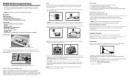
1. With the model resting on the ground, stand 30 paces (approx. 90 feet) away from the model.<br />
2. Face the model with the transmitter in your normal flying position. Place the transmitter in the range test<br />
screen (see page 51 or 98) and pull and hold the trainer switch on the top of the transmitter. This causes<br />
reduced power output from the transmitter.<br />
3. You should have total control of the model with the trainer switch pulled at 30 paces (90 feet).<br />
4. If control issues exist, call the Horizon Product Support Team at 1-877-504-0233 for further assistance.<br />
Pull and hold the trainer switch<br />
30 paces (90 feet)<br />
17
INDING<br />
The AR6200 receiver must be bound to the transmitter before it will operate. Binding is the process of teaching the<br />
receiver the specific code of the transmitter so it will connect to that specific transmitter. Once bound, the receiver<br />
will only connect to the transmitter when the previously bound model memory is selected. If another model<br />
memory is selected, the receiver will not connect. This feature is called <strong>Model</strong>Match and prevents flying a model<br />
using the wrong model memory.<br />
1. With the system hooked up as shown, insert the bind plug in the charge plug receptacle.<br />
2. Turn on the receiver switch (not included). Note that the LEDs on both receivers should be flashing,<br />
indicating that the receiver is ready to bind.<br />
18 SPEKTRUM DX6i • RADIO PROGRAMMING GUIDE
3. Establish the desired fail-safe stick positions: normally low throttle and flight controls neutral.<br />
4. Pull and hold the trainer switch on the top of the transmitter while turning on the power switch. Within<br />
a few seconds the system should connect. The LEDs on the receivers should go solid, indicating the<br />
system has connected.<br />
5. Remove the bind plug from the charge jack before turning off the receiver and store it in a<br />
convenient place.<br />
6. After you’ve programmed your model, it’s important to rebind the system so the true low throttle and<br />
neutral control surface positions are programmed.<br />
SPEKTRUM DX6i • RADIO PROGRAMMING GUIDE<br />
19
SMARTSAfE fAIl-SAfE<br />
The AR6200 features the SmartSafe fail-safe system.<br />
SMARtSAFe:<br />
• Prevents unintentional electric motor response on start-up.<br />
• Eliminates the possibility of over-driving servos on start-up.<br />
• Establishes low-throttle fail safe if the RF signal is lost.<br />
• Maintains last-commanded control surface position in the event of RF link interruption.<br />
Note: Fail-safe positions are stored via the stick and switch positions on the transmitter<br />
during binding.<br />
hOw SMARTSAfE wORKS<br />
Smartsafe is ideal for most types of electric aircraft and is also recommended for most types of gas- and glowpowered<br />
airplanes and helicopters. Here’s how SmartSafe works.<br />
RECEIvER POwER ONly<br />
When the receiver only is turned on (no transmitter signal is present), the throttle channel has no output, to avoid<br />
operating or arming the electronic speed control. In glow-powered models, the throttle servo has no input so it<br />
remains in its current position.<br />
AfTER CONNECTION<br />
When the transmitter is turned on, and after the receiver connects to the transmitter, normal control of all channels<br />
occurs. After the system makes a connection, if loss of signal occurs, SmartSafe drives the throttle servo only to its<br />
preset fail-safe position (low throttle) that was set during binding. All other channels hold their last position. When<br />
the signal is regained, the system immediately (less than 4 ms) regains control.<br />
20 SPEKTRUM DX6i • RADIO PROGRAMMING GUIDE
RECEIvER POwER SySTEM REqUIREMENTS<br />
With all radio installations, it is vital the onboard power system provides adequate power without interruption<br />
to the receiver even when the system is fully loaded (servos at maximum flight loads). This becomes especially<br />
critical with giant-scale models that utilize multiple high torque/ high current servos. Inadequate power systems<br />
that are unable to provide the necessary minimum voltage to the receiver during flight loads have become the<br />
number-one cause of in-flight failures. Some of the power system components that affect the ability to properly<br />
deliver adequate power include: the selected receiver battery pack (number of cells, capacity, cell type, state of<br />
charge), switch harness, battery leads, regulator (if used), power bus (if used).<br />
While Spektrum’s receivers’ minimum operational voltage is 3.5 volts, it is highly recommended the system<br />
be tested per the guidelines below to a minimum acceptable voltage of 4.8 volts during ground testing. This<br />
will provide head room to compensate for battery discharging or if the actual flight loads are greater than the<br />
ground test loads.<br />
RECOMMENDED POwER SySTEM GUIDElINES<br />
1. When setting up large or complex aircraft with multiple high torque servos, it’s highly recommend that<br />
a current and volt-meter (Hangar 9 HAN172) be used. Plug the volt-meter in an open channel port in<br />
the receiver and, with the system on, load the control surfaces (apply pressure with your hand) while<br />
monitoring the voltage at the receiver. The voltage should remain above 4.8 volts even when all servos<br />
are heavily loaded.<br />
Note: The optional Flight Log has a built-in volt meter and it can be used to perform this test.<br />
2. With the current meter in line with the receiver battery lead, load the control surfaces (apply pressure<br />
with your hand) while monitoring the current. The maximum continuous recommended current for a<br />
single heavy-duty servo/battery lead is three amps while short-duration current spikes of up to five<br />
amps are acceptable. Consequently, if your system draws more than three amps continuous or five<br />
amps for short durations, a single battery pack with a single switch harness plugged into the receiver for<br />
power will be inadequate. It will be necessary to use multiple packs with multiple switches and multiple<br />
leads plugged into the receiver.<br />
Note: The Flight log can not measure current draw. Please note that if the flight log is used to<br />
measure voltage, the HAN172 current meter still must be used to measure the draw of the servos.<br />
3. If using a regulator, it’s important the above tests are done for an extended period of 5 minutes. When<br />
current passes through a regulator, heat is generated. This heat causes the regulator to increase<br />
resistance, which in turn causes even more heat to build up (thermal runaway). While a regulator may<br />
provide adequate power for a short duration, it’s important to test its ability over time as the regulator<br />
may not be able to maintain voltage at significant power levels.<br />
4. For really large aircraft or complex models (for example 35% and larger or jets) multiple battery packs<br />
with multiple switch harnesses are necessary or in many cases one of the commercially available power<br />
boxes/ busses is recommended. No matter what power systems you choose, always carry out test #1<br />
above making sure that the receiver is constantly provided with 4.8 volts or more under all conditions.<br />
5. The latest generation of Nickel Metal Hydride batteries incorporate a new chemistry mandated to be<br />
more environmentally friendly. These batteries, when charged with peak detection fast chargers, have<br />
tendencies to false peak (not fully charge) repeatedly. These include all brands of NiMH batteries. If<br />
using NiMH packs be especially cautious when charging making absolutely sure that the battery is fully<br />
charged. It is recommended to use a charger that can display total charge capacity. Note the number of<br />
mAh put into a discharged pack to verify it has been charged to full capacity.<br />
SPEKTRUM DX6i • RADIO PROGRAMMING GUIDE<br />
21
TIPS ON USING 2.4Ghz SySTEMS<br />
Your DSM2 equipped <strong>2.4GHz</strong> system is intuitive to operate, functioning nearly identically to 72MHz systems.<br />
Following are a few common questions from customers:<br />
1. Q: Which do I turn on first, the transmitter or the receiver?<br />
A: It doesn’t matter, if the receiver is turned on first-the throttle channel doesn’t put out a pulse position<br />
at this time, preventing the arming of electronic speed controllers, or in the case of an engine powered<br />
aircraft, the throttle servo remains in its current position. When the transmitter is then turned on<br />
the transmitter scans the <strong>2.4GHz</strong> band and acquires two open channels. Then the receiver that was<br />
previously bound to the transmitter scans the band and finds the GUID (Globally Unique Identifier code)<br />
stored during binding. The system then connects and operates normally. If the transmitter is turned<br />
on first, the transmitter scans the <strong>2.4GHz</strong> band and acquires two open channels. When the receiver<br />
is turned on, the receiver scans the <strong>2.4GHz</strong> band looking for the previously stored GUID, and when it<br />
locates the specific GUID code and confirms uncorrupted repeatable packet information, the system<br />
connects and normal operation takes place. Typically this takes 2 to 6 seconds.<br />
2. Q: Sometimes the system takes longer to connect and sometimes it doesn’t connect at all. Why?<br />
A In order for the system to connect (after the receiver is bound) the receiver must receive a large number<br />
of continuous (one after the other) uninterrupted perfect packets from the transmitter in order to connect.<br />
This process is purposely critical of the environment ensuring that it’s safe to fly when the system does<br />
connect. If the transmitter is too close to the receiver (less that 4 feet) or if the transmitter is located near<br />
metal objects (metal transmitter case, the bed of a truck, the top of a metal work bench, etc.) connection<br />
will take longer and in some cases connection will not occur as the system is receiving reflected <strong>2.4GHz</strong><br />
energy from itself and is interpreting this as unfriendly noise. Moving the system away from metal<br />
objects or moving the transmitter away from the receiver and powering the system up again will cause<br />
a connection to occur. This only happens during the initial connection. Once connected the system<br />
is locked, and should a loss of signal occur (fail-safe), the system connects immediately (4ms) when<br />
signal is regained.<br />
3. Q: I’ve heard that the DSM system is less tolerant of low voltage. Is this correct?<br />
A: All DSM receivers have an operational voltage range of 3.5 to 9 volts. With most systems this is not a<br />
problem as in fact most servos cease to operate at around 3.8 volts. When using multiply high current<br />
draw servos with a single or inadequate battery/ power source, heavy momentary loads can cause the<br />
voltage to dip below this 3.5 volt threshold thus causing the entire system (servos and receiver) to<br />
brown out. When the voltage drops below the low voltage threshold (3.5 volts), the DSM receiver must<br />
reboot (go through the start up process of scanning the band and finding the transmitter) and this can<br />
take several seconds.<br />
Note: Receivers manufactured after July of 2007 offer a quick connect feature that reconnect<br />
immediately when recovering from a low voltage “brown out.”<br />
Please read the receiver power requirement on page 21 as this explains how to test for and prevent<br />
this occurrence.<br />
22 SPEKTRUM DX6i • RADIO PROGRAMMING GUIDE
4. Q: Sometimes my receiver loses its bind and won’t connect, requiring rebinding. What happens if the<br />
bind is lost in flight?<br />
A: The receiver will never lose its bind unless it’s instructed to. It’s important to understand that during<br />
the binding process the receiver not only learns the GUID (code) of the transmitter but the transmitter<br />
learns and stores the type of receiver that it’s bound to. If the trainer switch is pulled on the transmitter<br />
at any time and the transmitter is turned on, the transmitter looks for the binding protocol signal from<br />
a receiver. If no signal is present, the transmitter no longer has the correct information to connect to a<br />
specific receiver and in essence the transmitter has been “unbound” from the receiver. We’ve had several<br />
customers using transmitter stands or trays that unknowingly depress the bind button and the system is<br />
then turned on, losing the necessary information to allow the connection to take place. We’ve also had<br />
customers that didn’t fully understand the range test process and pull the trainer switch before turning<br />
on the transmitter, also causing the system to “lose its bind.” If the system fails to connect, one of the<br />
following has occurred:<br />
• The wrong model has been selected in the model memory (<strong>Model</strong>Match).<br />
• The transmitter is near conductive material (transmitter case, truck bed, etc.) and the reflected <strong>2.4GHz</strong><br />
energy is preventing the system from connecting. (See #2 above)<br />
• The trainer switch was pulled and the radio was turned on unknowingly (or knowingly) previously,<br />
causing the transmitter to no longer recognize the receiver.<br />
SPEKTRUM DX6i • RADIO PROGRAMMING GUIDE<br />
23
AIRPlANE qUICK START<br />
The following covers a basic 4-channel airplane with a single rate. For more details on programming for the<br />
aircraft mode, see the Aircraft section of this manual.<br />
MODEl TyPE SElECTION<br />
SElECTING AIRPlANE MODE<br />
Press the ROLLER and hold while turning on the transmitter. When SETUP LIST appears on screen,<br />
release the roller.<br />
MODEL TYPE appears on the lower section of the screen.<br />
Rotate the roller to highlight MODEL TYPE.<br />
Reduce photo to 13.5%<br />
SETUP LIST<br />
MODEL TYPE<br />
Reduce photo to 13.5%<br />
SETUP LIST<br />
MODEL TYPE<br />
24 SPEKTRUM DX6i • RADIO PROGRAMMING GUIDE<br />
Main<br />
Main<br />
Press the ROLLER to access the MODEL TYPE function. If ACRO is highlighted on screen, proceed to SERVO.<br />
Reduce photo to 13.5%<br />
MODEL TYPE<br />
ACRO<br />
HELI<br />
1<br />
List
SERvO REvERSING<br />
TO ACCESS SERvO REvERSING<br />
Press the ROLLER and hold while turning on the transmitter. When SETUP LIST appears on screen<br />
release the roller.<br />
You can also turn the transmitter on and press the scroll wheel. Scroll down to the setup list and press the scroll<br />
wheel to get to this screen.<br />
MODEL TYPE appears on the lower section of the screen.<br />
SPEKTRUM DX6i • RADIO PROGRAMMING GUIDE<br />
Reduce photo to 13.5%<br />
SETUP LIST<br />
MODEL TYPE<br />
Rotate the ROLLER to the right until REVERSE is highlighted on screen.<br />
Reduce photo to 13.5%<br />
SETUP LIST<br />
MONITOR<br />
REVERSE<br />
THRO CUT<br />
Main<br />
Main<br />
4<br />
25
Press the roller to access the reversing function.<br />
Reduce photo to 13.5%<br />
THRO-N<br />
ELEV-N<br />
GEAR-N<br />
REVERSE<br />
AILE-N<br />
RUDD-N<br />
FLAP-N<br />
26 SPEKTRUM DX6i • RADIO PROGRAMMING GUIDE<br />
List<br />
Rotate the roller to highlight the desired channel then press the roller to select that channel.<br />
With the desired channel selected rotate the roller to select N- normal or R reverse.<br />
When the reverse direction is correct, press the roller to deselect the channel.<br />
To return to the SETUP LIST rotate the roller and highlight LIST then press the roller.
TRAvEl ADjUST<br />
TO ACCESS TRAvEl ADjUST<br />
With the transmitter already powered on and in the main screen, press and release the ROLLER to enter<br />
the ADJUST LIST.<br />
SPEKTRUM DX6i • RADIO PROGRAMMING GUIDE<br />
Reduce photo to 13.5%<br />
ADJUST LIST<br />
MODEL SELECT<br />
Main<br />
Rotate the ROLLER to the right until TRAVEL ADJ is highlighted on screen.<br />
Reduce photo to 13.5%<br />
ADJUST LIST<br />
D/R&EXPO<br />
TRAVEL ADJ<br />
SUB TRIM<br />
Main<br />
3<br />
27
Press the roller to access the TRAVEL ADJ function.<br />
Reduce photo to 13.5%<br />
TRAVEL ADJ<br />
THRO+<strong>10</strong>0%<br />
ELEV+<strong>10</strong>0%<br />
GEAR+<strong>10</strong>0%<br />
Rotate the roller to highlight the desired channel.<br />
AILE+<strong>10</strong>0%<br />
RUDD+<strong>10</strong>0%<br />
FLAP+<strong>10</strong>0%<br />
28 SPEKTRUM DX6i • RADIO PROGRAMMING GUIDE<br />
List<br />
Move the corresponding channel’s stick or switch in the desired direction and hold the stick you wish to change<br />
the travel adjust and note the arrow direction then press the roller to select that channel and direction.<br />
Rotate the roller to adjust the travel adjust values in that selected direction only.<br />
When the desired value is selected press the roller to deselect the channel.<br />
Repeat for all other channels.<br />
This completes the basic Quick Start setup for your airplane. For additional features like Dual and Expo rates,<br />
Mixing, etc, see the appropriate pages listed in the table of contents.<br />
Note: If your airplane’s ailerons are controlled independently by two servos, see “WING TAIL MIX<br />
Selection” on page 43 for specifics on programming DUAL AILERONS.
AIRCRAfT PROGRAMMING GUIDE<br />
CONTROl IDENTIfICATION AND lOCATION - MODE 2<br />
Gear/Flight Mode<br />
Elevator Dual Rate<br />
Throttle/Rudder<br />
Stick<br />
Rudder Trim<br />
Throttle Trim<br />
ThROTTlE AlT<br />
Trainer/Bind<br />
The Throttle ALT function makes the throttle stick trim active only when the throttle stick is at less than half throttle.<br />
This allows accurate idle adjustments without affecting the mid to high throttle position.<br />
SPEKTRUM DX6i • RADIO PROGRAMMING GUIDE<br />
Antenna<br />
Flap/Gyro<br />
On/Off Switch<br />
Handle<br />
Throttle Cut<br />
Mix/Throttle Hold<br />
Rudder Dual Rate<br />
Aileron Dual Rate<br />
Aileron/Elevator<br />
Stick<br />
Elevator Trim<br />
Aileron Trim<br />
Roller<br />
29
lOw bATTERy AlARM<br />
TRAINER<br />
When the battery voltage drop below 4.3 volts an alarm will sound and the screen will flash.<br />
The DX6i offers a Trainer function that allows the transmitter to operate as a master or slave. The trainer switch is<br />
located on the back left of the transmitter. (The trainer switch is located on the back right on Mode 1 transmitters.)<br />
MASteR<br />
The transmitter can be used as a master but the slave transmitter must have the same programming (i.e. reverse,<br />
travel adjust, dual rates, mixes, sub trims, etc.) as the master.<br />
SlAvE MODE<br />
When using the transmitter as a slave with another DX6i, it’s necessary to match all the programmable settings (i.e.<br />
reverse, travel adjust, etc.).<br />
PROGRAMMING USING ThE ROllER<br />
The roller is used to access all programming functions.<br />
• Pressing and releasing the roller accesses/ enters the selected function<br />
• Rolling the roller changes values or selections<br />
TO ACCESS ThE MAIN SCREEN:<br />
Anytime the transmitter is turned on, the main screen will appear.<br />
TO RETURN TO ThE MAIN SCREEN:<br />
Reduce photo to 13.5%<br />
MDL6<br />
5.0V<br />
MUSTANG<br />
DN06:00<br />
From the ADJUST LIST or SETUP LIST screens, pressing and holding the roller for more than three seconds then<br />
releasing the roller will return the display to the main screen.<br />
TO RETURN TO ThE lIST OR SETUP SCREEN:<br />
From the any program function screens, pressing and holding the roller for more than three seconds then releasing<br />
the roller will return the display to the LIST of SETUP screen.<br />
30 SPEKTRUM DX6i • RADIO PROGRAMMING GUIDE
SETUP lIST<br />
The SETUP list contains the programming functions that are normally only used during the initial setup of the<br />
model. (i.e. model type, servo reverse, model name).<br />
THR<br />
AIL<br />
ELE<br />
RUD<br />
CH5<br />
AUX<br />
Reduce photo to 13.5%<br />
MODEL TYPE<br />
ACRO<br />
Reduce photo to 13.5%<br />
MODEL NAME<br />
MODEL 6<br />
MUSTANG<br />
HELI<br />
<strong>Model</strong> Type (Page 33)<br />
<strong>Model</strong> Name (Page 35)<br />
Reduce photo to 13.5%<br />
Reduce photo to 13.5%<br />
THRO-N<br />
ELEV-N<br />
GEAR-N<br />
List<br />
List<br />
MONITOR List<br />
[ ]<br />
[ ]<br />
[ ]<br />
◊<br />
◊<br />
◊<br />
◊<br />
◊<br />
◊<br />
Monitor (Page 37)<br />
REVERSE<br />
AILE-N<br />
RUDD-N<br />
FLAP-N<br />
Reverse (Page 39)<br />
List<br />
The SETUP LIST includes programming functions that are normally used during set up. Setup programming<br />
functions for airplanes include those listed above.<br />
SPEKTRUM DX6i • RADIO PROGRAMMING GUIDE<br />
Reduce photo to 13.5%<br />
THRO CUT<br />
POSITION - ACT<br />
Throttle Cut (Page 41)<br />
Reduce photo to 13.5%<br />
WINGTAILMIX<br />
DUALAILE INH<br />
V-TAIL INH<br />
ELEVON INH<br />
Wing Tail Mix (Page 43)<br />
Reduce photo to 13.5%<br />
D/R COMBI<br />
D/R SW: INH<br />
D/R Combi (Page 46)<br />
Reduce photo to 13.5%<br />
TIMER<br />
MDL6 MUSTANG<br />
DOWN TIMER-06:00<br />
SWITCH---TRAINER<br />
Timer (Page 48)<br />
List<br />
List<br />
List<br />
List<br />
Reduce photo to 13.5%<br />
RANGE CHECK<br />
CHECK INH<br />
<strong>Range</strong> Check (Page 50)<br />
Reduce photo to 13.5%<br />
POWER SETTING<br />
A-EU 328<br />
Power Setting (Page 52)<br />
Reduce photo to 13.5%<br />
CONTRAST<br />
50%<br />
Contrast (Page 53)<br />
Reduce photo to 13.5%<br />
COPY/RESET<br />
MODEL 6 MUSTANG<br />
COPY TO 1<br />
SURE? NO/YES<br />
Copy/Reset (Page 55)<br />
Reduce photo to 13.5%<br />
ADJUST LIST<br />
MODEL SELECT<br />
Adjust List (Page 58)<br />
List<br />
List<br />
List<br />
List<br />
Main<br />
31
TO ENTER ThE SETUP lIST<br />
Press the ROLLER and hold while turning on the transmitter. When SETUP LIST appears on screen,<br />
release the roller.<br />
Reduce photo to 13.5%<br />
SETUP LIST<br />
MODEL TYPE<br />
32 SPEKTRUM DX6i • RADIO PROGRAMMING GUIDE<br />
Main<br />
Alternatively the setup list can be accessed from the main screen by pressing the roller to access the ADJUST LIST<br />
then scrolling through the ADJUST LIST by rolling the roller to highlight SETUP LIST; then press the roller and the<br />
SETUP LIST will appear.<br />
TO EXIT ThE SETUP lIST<br />
Press and hold the roller for more than 3 seconds, then release the roller and the system will return to<br />
the main screen.<br />
Alternatively rotating the roller to highlight MAIN in the upper right corner then pressing the roller will return<br />
the system to the main screen.<br />
Turning the transmitter off then back on will return the transmitter to the main screen.
MODEl TyPE fUNCTION<br />
The DX6i features two programming types: Airplane and Helicopter. The DX6i can memorize data for up to <strong>10</strong><br />
models individually and the model type will automatically be stored with each model memory.<br />
TO ENTER ThE MODEl TyPE fUNCTION<br />
Press the ROLLER and hold while turning on the transmitter. When SETUP LIST appears on screen<br />
release the roller.<br />
Alternatively the setup list can be accessed from the main screen by pressing the roller to access the ADJUST LIST<br />
then scrolling through the ADJUST LIST by rolling the roller to highlight SETUP LIST then press the roller.<br />
MODEL TYPE appears on the lower section of the screen.<br />
SPEKTRUM DX6i • RADIO PROGRAMMING GUIDE<br />
Reduce photo to 13.5%<br />
SETUP LIST<br />
MODEL TYPE<br />
Main<br />
Rotate the roller to highlight MODEL TYPE then press the roller to access the MODEL TYPE function.<br />
Reduce photo to 13.5%<br />
SETUP LIST<br />
MODEL TYPE<br />
Main<br />
1<br />
33
TO SElECT A MODEl TyPE<br />
Rotate the roller to highlight the desired model type ACRO (airplane) or HELI helicopter then press the roller<br />
to program that model type in model memory. Note that when changing model type all programming from the<br />
previous model will be erased and the new model will be reset to factory default settings.<br />
TO RETURN TO ThE MAIN SCREEN<br />
Reduce photo to 13.5%<br />
MODEL TYPE<br />
ACRO<br />
HELI<br />
34 SPEKTRUM DX6i • RADIO PROGRAMMING GUIDE<br />
List<br />
Press and hold the roller for more than 3 seconds then release the roller and the system will return<br />
to the main screen.<br />
TO RETURN TO ThE SETUP lIST<br />
Rotate the roller to highlight LIST in the upper right corner then pressing the roller will return the system to the<br />
SETUP LIST screen.
MODEl NAME<br />
The <strong>Model</strong> Name function is used to input and assign the model’s name to a specific memory, allowing easy<br />
identification of each model’s program. Each model’s name is displayed on the main screen when that model is<br />
selected. Up to eight characters that include numbers and letters are available.<br />
TO ENTER ThE MODEl NAME fUNCTION<br />
Press the ROLLER and hold while turning on the transmitter. When SETUP LIST appears on screen<br />
release the roller.<br />
Alternatively the setup list can be accessed from the main screen by pressing the roller to access the ADJUST LIST<br />
then scrolling through the ADJUST LIST by rolling the roller to highlight SETUP LIST then press the roller.<br />
MODEL TYPE appears on the lower section of the screen.<br />
SPEKTRUM DX6i • RADIO PROGRAMMING GUIDE<br />
Reduce photo to 13.5%<br />
SETUP LIST<br />
MODEL TYPE<br />
Main<br />
Rotate the roller to highlight MODEL NAME then press the roller to access the MODEL NAME function.<br />
Reduce photo to 13.5%<br />
SETUP LIST<br />
1<br />
Main<br />
MODEL TYPE<br />
MODEL NAME 2<br />
MONITOR<br />
35
TO PROGRAM A MODEl NAME<br />
Rotate the roller to highlight the block below the MODEL # shown on the screen then press the roller.<br />
Reduce photo to 13.5%<br />
MODEL NAME<br />
MODEL 6<br />
MUSTANG<br />
36 SPEKTRUM DX6i • RADIO PROGRAMMING GUIDE<br />
List<br />
Rotate the roller to select the desired position that you wish to assign a letter or number then press the roller to<br />
access the numbers or letter characters.<br />
Rotate the roller to scroll through the letters/ numbers and when the desired number is selected pressing the roller<br />
will assign it to the selected position.<br />
Repeat this process to complete the model name then highlight OK! When finished.<br />
TO RETURN TO ThE MAIN SCREEN<br />
Press and hold the roller for more than 3 seconds then release the roller and the system will return<br />
to the main screen.<br />
TO RETURN TO ThE SETUP lIST<br />
Rotate the roller to highlight LIST in the upper right corner then pressing the roller will return the system to the<br />
SETUP LIST screen.
MONITOR<br />
The servo monitor screen serves as a useful tool when programming your radio. It displays servo movement and<br />
direction when different programming functions, sticks and/or switches are moved.<br />
TO ACCESS ThE SERvO MONITOR<br />
Press the ROLLER and hold while turning on the transmitter to enter the SETUP LIST. When SETUP LIST appears<br />
on screen release the roller.<br />
Alternatively the setup list can be accessed from the main screen by pressing the roller to access the ADJUST LIST<br />
then scrolling through the ADJUST LIST by rolling the roller to highlight SETUP LIST then press the roller.<br />
SPEKTRUM DX6i • RADIO PROGRAMMING GUIDE<br />
Reduce photo to 13.5%<br />
SETUP LIST<br />
MODEL TYPE<br />
Rotate the ROLLER to the right until SERVO is highlighted on screen.<br />
Reduce photo to 13.5%<br />
SETUP LIST<br />
Main<br />
Main<br />
MODEL NAME<br />
MONITOR 3<br />
REVERSE<br />
37
Press the roller to access the Servo monitor screen.<br />
TO RETURN TO ThE MAIN SCREEN<br />
THR<br />
AIL<br />
ELE<br />
RUD<br />
CH5<br />
AUX<br />
Reduce photo to 13.5%<br />
MONITOR List<br />
[ ]<br />
[ ]<br />
[ ]<br />
◊<br />
Press and hold the roller for more than 3 seconds then release the roller and the system will return<br />
to the main screen.<br />
◊<br />
TO RETURN TO ThE SETUP lIST<br />
Rotate the roller to highlight LIST in the upper right corner then pressing the roller will return the system to the<br />
SETUP LIST screen.<br />
38 SPEKTRUM DX6i • RADIO PROGRAMMING GUIDE<br />
◊<br />
◊<br />
◊<br />
◊
REvERSE<br />
The Reverse Switch function allows electronic means of reversing the servo’s throw. Servo reversing is available<br />
for all six channels.<br />
TO ACCESS ThE REvERSE fUNCTION<br />
Press the ROLLER and hold while turning on the transmitter. When SETUP LIST appears on screen<br />
release the roller.<br />
Alternatively the setup list can be accessed from the main screen by pressing the roller to access the ADJUST LIST<br />
then scrolling through the ADJUST LIST by rolling the roller to highlight SETUP LIST then press the roller.<br />
SPEKTRUM DX6i • RADIO PROGRAMMING GUIDE<br />
Reduce photo to 13.5%<br />
SETUP LIST<br />
MODEL TYPE<br />
Main<br />
Rotate the roller to highlight REVERSE then press the roller to access the REVERSE function.<br />
Reduce photo to 13.5%<br />
SETUP LIST<br />
MONITOR<br />
REVERSE<br />
THRO CUT<br />
Main<br />
4<br />
39
TO REvERSE A ChANNEl<br />
Rotate the roller to highlight the desired channel then press the roller to select that channel.<br />
Reduce photo to 13.5%<br />
THRO-N<br />
ELEV-N<br />
GEAR-N<br />
REVERSE<br />
AILE-N<br />
RUDD-N<br />
FLAP-N<br />
40 SPEKTRUM DX6i • RADIO PROGRAMMING GUIDE<br />
List<br />
With the desired channel selected rotate the roller to select (N=Normal, R=Reverse).<br />
• THRO: Throttle<br />
• AILE: Aileron<br />
• ELEV: Elevator<br />
• RUDD: Rudder<br />
• GEAR: Retractable Landing Gear<br />
• FLAP: Flap<br />
When the reverse direction is selected press the roller to deselect the channel.<br />
TO RETURN TO ThE MAIN SCREEN<br />
Press and hold the roller for more than 3 seconds then release the roller and the system will return<br />
to the main screen.<br />
TO RETURN TO ThE SETUP lIST<br />
Rotate the roller to highlight LIST in the upper right corner then pressing the roller will return the system to the<br />
SETUP LIST screen.
ThROTTlE CUT<br />
The DX6i offers a Throttle Cut function. When the Throttle Cut button is pressed, the throttle moves to the low<br />
throttle, low trim position, allowing the safe and convenient shut down of the engine.<br />
TO ACTIvATE ThE ThROTTlE CUT fUNCTION<br />
Press the ROLLER and hold while turning on the transmitter. When SETUP LIST appears on screen<br />
release the roller.<br />
SPEKTRUM DX6i • RADIO PROGRAMMING GUIDE<br />
Reduce photo to 13.5%<br />
SETUP LIST<br />
MODEL TYPE<br />
Main<br />
Alternatively the setup list can be accessed from the main screen by pressing the roller to access the ADJUST LIST,<br />
then scrolling through the ADJUST LIST by rolling the roller to highlight SETUP LIST, then pressing the roller.<br />
Reduce photo to 13.5%<br />
SETUP LIST<br />
REVERSE<br />
THRO CUT<br />
WINGTAILMIX<br />
Main<br />
Rotate the roller to highlight THRO CUT then press the roller to access the Throttle Cut function.<br />
Reduce photo to 13.5%<br />
THRO CUT<br />
POSITION - INH<br />
5<br />
List<br />
41
TO PROGRAM A ThROTTlE CUT<br />
Rotate the roller to highlight INH then press the roller to highlight INH. Now rotate the roller to ACT or INH the<br />
Throttle Cut function.<br />
TO RETURN TO ThE MAIN SCREEN<br />
Reduce photo to 13.5%<br />
THRO CUT<br />
POSITION - ACT<br />
42 SPEKTRUM DX6i • RADIO PROGRAMMING GUIDE<br />
List<br />
Press and hold the roller for more than 3 seconds then release the roller and the system will return<br />
to the main screen.<br />
TO RETURN TO ThE SETUP lIST<br />
Rotate the roller to highlight LIST in the upper right corner then pressing the roller will return the system<br />
to the SETUP LIST screen.
wING TAIl MIX<br />
The DX6i offers three different wing types to choose from: Normal, Dual aileron and Elevon (also called Delta<br />
mixing). In addition, V-Tail mixing is available from this screen.<br />
NORMAl<br />
When the DUALAILE and ELEVON wing function are INH, Normal wing type is selected. Use this wing type with<br />
common aircraft that utilize only one servo for both ailerons. Normal is the default setting.<br />
When the V-tail function is INH, normal tail function (separate elevator and rudder) is selected.<br />
DUAl AIlERON wING TyPE SElECTION<br />
Dual Ailerons require the use of one servo for each aileron and allow the use of ailerons as flaps or spoilers. This<br />
function also allows the precise independent adjustment of up and down travel, and independent sub-trim and<br />
differential of each aileron.<br />
v-TAIl SElECTION<br />
V-tail combines the elevator and rudder channel to provide pitch and yaw control when using a V-tail equipped<br />
airplane. This function also allows the precise independent adjustment of up and down travel, and independent<br />
sub-trim and dual rate adjustments of the V-tail’s control surfaces.<br />
ElEvON wING TyPE SElECTION<br />
Elevon wing arrangements combine the function of ailerons with the function of the elevator to allow precise<br />
control of both roll and pitch.<br />
TO ENTER ThE wING TAIl MIX fUNCTION<br />
Press the ROLLER and hold while turning on the transmitter. When SETUP LIST appears on screen<br />
release the roller.<br />
Alternatively the setup list can be accessed from the main screen by pressing the roller to access the ADJUST LIST,<br />
then scrolling through the ADJUST LIST by rolling the roller to highlight SETUP LIST, then pressing the roller.<br />
SPEKTRUM DX6i • RADIO PROGRAMMING GUIDE<br />
Reduce photo to 13.5%<br />
SETUP LIST<br />
MODEL TYPE<br />
Main<br />
43
Rotate the roller to highlight WINGTAILMIX then press the roller to access the Wing tail mix function.<br />
TO SElECT A wING/TAIl TyPE<br />
Reduce photo to 13.5%<br />
SETUP LIST<br />
THRO CUT<br />
WINGTAILMIX 6<br />
D/R COMBI<br />
44 SPEKTRUM DX6i • RADIO PROGRAMMING GUIDE<br />
Main<br />
Rotate the roller to highlight the desired wing or tail type then press the roller to highlight the desired function.<br />
Rotate the roller to inhibit (INH) or activate (ACT) the function.<br />
Reduce photo to 13.5%<br />
WINGTAILMIX<br />
DUALAILE INH<br />
V-TAIL INH<br />
ELEVON INH<br />
List<br />
Note: When Flaperon or Delta Wing type is selected, the travel adjustment is used to adjust the<br />
individual servo throw, while the combined aileron travel is adjusted with the aileron dual rate. It<br />
is also possible to set aileron differential. Reverse switches are applicable for each servo. Neutral<br />
adjustments of each servo are made by the Sub Trim Function.
DUAl AIlERON wING TyPE SERvO CONNECTIONS<br />
• AILE servo port (right aileron)<br />
• AUX1 servo port (left aileron)<br />
AUX1 Servo Port<br />
(Left Aileron)<br />
• RUDD servo port (right V-tail)<br />
• ELEV servo port (left V-tail)<br />
SPEKTRUM DX6i • RADIO PROGRAMMING GUIDE<br />
Dual Aileron Wing Type Connection<br />
ELEV Servo Port<br />
(Left V-Tail)<br />
• ELEV servo port (right aileron)<br />
• AILE servo port (left aileron)<br />
TO RETURN TO ThE MAIN SCREEN<br />
V-Tail Type Connection<br />
AILE Servo Port<br />
(Left Aileron)<br />
AILE Servo Port<br />
(Right Aileron)<br />
Elevon Wing Type Connection<br />
RUDD Servo Port<br />
(Right V-Tail)<br />
ELEV Servo Port<br />
(Right Aileron)<br />
Press and hold the roller for more than 3 seconds then release the roller and the system will return<br />
to the main screen.<br />
TO RETURN TO ThE SETUP lIST<br />
Rotate the roller to highlight LIST in the upper right corner then pressing the roller will return the system to the<br />
SETUP LIST screen.<br />
45
D/R COMbI SwITCh ASSIGNMENT<br />
The Dual Rate Combi switch assignment function allows the aileron, elevator and rudder dual rate and exponential<br />
functions to be assigned to one of four common switches such that the dual rates/expos for all three channels can<br />
be accessed using a single switch.<br />
TO ACCESS DUAl RATE COMbI ASSIGNMENT<br />
To access the dual rate combi function rotate the roller to highlight D/R COMBI then press the roller to access the<br />
Dual Rate Combi function.<br />
Reduce photo to 13.5%<br />
SETUP LIST<br />
MODEL TYPE<br />
Reduce photo to 13.5%<br />
SETUP LIST<br />
WINGTAILMIX<br />
D/R&COMBI<br />
TIMER<br />
46 SPEKTRUM DX6i • RADIO PROGRAMMING GUIDE<br />
Main<br />
Main<br />
7
Rotate the roller to highlight IHN then press the roller. Now rotate the roller to select AILE, ELEV, RUDD or GEAR.<br />
TO RETURN TO ThE MAIN SCREEN<br />
SPEKTRUM DX6i • RADIO PROGRAMMING GUIDE<br />
Reduce photo to 13.5%<br />
D/R COMBI<br />
D/R SW: INH<br />
List<br />
Press and hold the roller for more than 3 seconds then release the roller and the system will return<br />
to the main screen.<br />
TO RETURN TO ThE SETUP lIST<br />
Rotate the roller to highlight LIST in the upper right corner then pressing the roller will return the system to the<br />
SETUP LIST screen.<br />
Note: If INH is selected the aileron, elevator and rudder dual rate and expo functions independently<br />
operate using their respective switches.<br />
47
TIMER<br />
The DX6i features an on screen timer with two programming options:<br />
DOwN-TIMER:<br />
Down Timer - The countdown timer allows a preset time in ten-second intervals up to 59 minutes and 50 seconds<br />
to be programmed, and when that time expires, a beeper will sound five (5) beeps every five (5) seconds.<br />
UP-TIMER:<br />
Up Timer - The up timer function is a simple count-up timer that displays minutes and seconds up to 59<br />
minutes and 59 seconds. The start time can be programmed. In most cases the default start setting of 00:00 is<br />
recommended.<br />
When the DOWN-TIMER or UP-TIMER function is selected, the timer will be displayed on the main screen. The<br />
following buttons are used in conjunction to operate the timer function:<br />
Trainer Timer button- when programmed Used to stop start and reset the timer.<br />
Throttle Cut button- when programmed Used to start stop and reset the timer.<br />
Note: To reset the timer press and hold the assigned timer switch (throttle cut or trainer) for more<br />
than 3 seconds.<br />
TO SElECT ThE TIMER fUNCTION<br />
Press the ROLLER and hold while turning on the transmitter. When SETUP LIST appears on screen<br />
release the roller.<br />
Alternatively the setup list can be accessed from the main screen by pressing the roller to access the ADJUST LIST<br />
then scrolling through the ADJUST LIST by rolling the roller to highlight SETUP LIST then press the roller.<br />
Reduce photo to 13.5%<br />
SETUP LIST<br />
MODEL TYPE<br />
Main<br />
48 SPEKTRUM DX6i • RADIO PROGRAMMING GUIDE
SPEKTRUM DX6i • RADIO PROGRAMMING GUIDE<br />
Reduce photo to 13.5%<br />
SETUP LIST<br />
D/R COMBI<br />
TIMER<br />
RANGE CHECK<br />
Main<br />
Rotate the roller to highlight TIMER then press the roller to access the Timer function.<br />
TO PROGRAM ThE TIMER fUNCTION<br />
Reduce photo to 13.5%<br />
TIMER<br />
MDL6 MUSTANG<br />
DOWN TIMER-06:00<br />
SWITCH---TRAINER<br />
8<br />
List<br />
Rotate the roller to highlight the desired timer function that you wish to change.<br />
UP/ Down- selects the up or down timer function<br />
TIME- in minutes or seconds<br />
Switch Options- Trainer or Throttle Cut<br />
When the desired function is highlighted press the roller to access the function.<br />
Rotate the roller to change the option or value.<br />
TO RETURN TO ThE MAIN SCREEN<br />
Press and hold the roller for more than 3 seconds then release the roller and the system will return<br />
to the main screen.<br />
TO RETURN TO ThE SETUP lIST<br />
Rotate the roller to highlight LIST in the upper right corner then pressing the roller will return the system to the<br />
SETUP LIST screen.<br />
49
RANGE ChECK<br />
RANGE CHECK: When activated the <strong>Range</strong> Check screen allows for a range check by using the trainer switch to<br />
reduce the output power.<br />
TO ENTER ThE RANGE ChECK fUNCTION<br />
Press the ROLLER and hold while turning on the transmitter. When SETUP LIST appears on screen release the<br />
roller.<br />
Alternatively the setup list can be accessed from the main screen by pressing the roller to access the ADJUST LIST,<br />
then scrolling through the ADJUST LIST by rolling the roller to highlight SETUP LIST, then pressing the roller.<br />
Reduce photo to 13.5%<br />
SETUP LIST<br />
MODEL TYPE<br />
50 SPEKTRUM DX6i • RADIO PROGRAMMING GUIDE<br />
Main<br />
Rotate the roller to highlight RANGE CHECK then press the roller to access the RANGE CHECK function.<br />
Reduce photo to 13.5%<br />
SETUP LIST<br />
TIMER<br />
RANGE CHECK<br />
POWER SETTING<br />
Main<br />
9
RANGE ChECKING A MODEl<br />
Rotate the roller to highlight RANGE and press the roller to access the range function.<br />
hOw TO RANGE TEST ThE DX6I<br />
RANGE TESTING ThE DX6I<br />
SPEKTRUM DX6i • RADIO PROGRAMMING GUIDE<br />
Reduce photo to 13.5%<br />
RANGE CHECK<br />
CHECK INH<br />
List<br />
1. With the model on and resting on the ground, stand 30 paces (approx. 90 feet) away from the model.<br />
2. Face the model with the transmitter in your normal flying position. Place the transmitter in the range<br />
test screen (see above) and pull and hold the trainer switch on the top of the transmitter. This causes<br />
reduced power output from the transmitter.<br />
3. You should have total control of the model with the button depressed at 30 paces (90 feet).<br />
Pull and hold the trainer switch<br />
30 paces (90 feet)<br />
4. If control issues exist, call the Horizon Product Support Team at 1-877-504-0233 for further assistance.<br />
51
POwER SETTING<br />
The power setting screen is used to place the transmitter in one of two power settings. A-EU 328 is appropriate<br />
for most European countries conforming to EU 300-328, while B-US 247 should be selected for use in the United<br />
States and countries outsde the EU.<br />
TO ENTER ThE POwER SETTING fUNCTION<br />
Press the ROLLER and hold while turning on the transmitter. When SETUP LIST appears on screen<br />
release the roller.<br />
Alternatively the setup list can be accessed from the main screen by pressing the roller to access the ADJUST LIST,<br />
then scrolling through the ADJUST LIST by rolling the roller to highlight POWER SETTING, then press the roller to<br />
access the POWER setting function.<br />
Reduce photo to 13.5%<br />
SETUP LIST<br />
RANGE CHECK<br />
POWER SETTING<br />
CONTRAST<br />
Reduce photo to 13.5%<br />
POWER SETTING<br />
A-EU 328<br />
52 SPEKTRUM DX6i • RADIO PROGRAMMING GUIDE<br />
Main<br />
<strong>10</strong><br />
List<br />
Rotate the roller to highlight the power setting then press the roller. Now rotate the roller to select A-EU 328 for EU<br />
countries outside of the US and B-US 247 if the system is to be used in the USA and in non EU countries.<br />
TO RETURN TO ThE MAIN SCREEN<br />
Press and hold the roller for more than 3 seconds then release the roller and the system will return<br />
to the main screen.<br />
TO RETURN TO ThE SETUP lIST<br />
Rotate the roller to highlight LIST in the upper right corner then pressing the roller will return the system to the<br />
SETUP LIST screen.
CONTRAST<br />
The contrast function allows the adjustment of the screen contrast.<br />
TO ACCESS ThE CONTRAST SCREEN<br />
Press the ROLLER and hold while turning on the transmitter. When SETUP LIST appears on screen<br />
release the roller.<br />
Alternatively the setup list can be accessed from the main screen by pressing the roller to access the ADJUST LIST,<br />
then scrolling through the ADJUST LIST by rolling the roller to highlight SETUP LIST, then pressing the roller.<br />
SPEKTRUM DX6i • RADIO PROGRAMMING GUIDE<br />
Reduce photo to 13.5%<br />
SETUP LIST<br />
MODEL TYPE<br />
Main<br />
Rotate the roller to highlight CONTRAST then press the roller to access the contrast function.<br />
Reduce photo to 13.5%<br />
SETUP LIST<br />
Main<br />
POWER SETTING<br />
CONTRAST 11<br />
COPY/RESET<br />
53
CONTRAST: Allows the adjustment of the screen contrast from 0 to<strong>10</strong>0%.<br />
Reduce photo to 13.5%<br />
CONTRAST<br />
50%<br />
Rotate the roller to adjust the screen contrast from 0 to <strong>10</strong>0%.<br />
TO RETURN TO ThE MAIN SCREEN<br />
54 SPEKTRUM DX6i • RADIO PROGRAMMING GUIDE<br />
List<br />
Press and hold the roller for more than 3 seconds then release the roller and the system will return<br />
to the main screen.<br />
TO RETURN TO ThE SETUP lIST<br />
Rotate the roller to highlight LIST in the upper right corner then pressing the roller will return the system to the<br />
SETUP LIST screen.
COPy/RESET<br />
The COPY function allows the current model memory that is being used to be transferred to any of the other 9<br />
available model memories. This is useful when experimenting with different model setups.<br />
The <strong>Model</strong> Reset function allows the model memory of the current model to be reset to the factory default setting.<br />
TO ENTER ThE COPy/RESET fUNCTION<br />
Press the ROLLER and hold while turning on the transmitter. When SETUP LIST appears on screen<br />
release the roller.<br />
Alternatively the setup list can be accessed from the main screen by pressing the roller to access the ADJUST LIST,<br />
then scrolling through the ADJUST LIST by rolling the roller to highlight SETUP LIST, then pressing the roller.<br />
SPEKTRUM DX6i • RADIO PROGRAMMING GUIDE<br />
Reduce photo to 13.5%<br />
SETUP LIST<br />
MODEL TYPE<br />
Main<br />
Rotate the roller to highlight COPY/RESET then press the roller to access the COPY/RESET function.<br />
Reduce photo to 13.5%<br />
SETUP LIST<br />
Main<br />
CONTRAST<br />
COPY/RESET 12<br />
ADJUST LIST<br />
55
TO ACCESS ThE COPy fUNCTION<br />
Rotate the roller to highlight COPY then press the roller to enter the COPY function.<br />
COPy SCREEN<br />
Rotate the roller to COPY and select the model memory that you wish to copy by pressing and<br />
rotating the roller.<br />
Reduce photo to 13.5%<br />
COPY/RESET<br />
MODEL 6 MUSTANG<br />
COPY<br />
RESET<br />
56 SPEKTRUM DX6i • RADIO PROGRAMMING GUIDE<br />
List<br />
When the desired model memory is selected, press the roller to highlight YES, next to SURE, and then press the<br />
roller to copy the model to the selected memory.<br />
Note: Be aware that the model you copy to will have its memory replaced with the new model’s<br />
memory, and the programming information for the model to be copied to will be erased.<br />
TO RETURN TO ThE MAIN SCREEN<br />
Press and hold the roller for more than 3 seconds then release the roller and the system will return<br />
to the main screen.<br />
TO RETURN TO ThE SETUP lIST<br />
Rotate the roller to highlight LIST in the upper right corner then pressing the roller will return the system to the<br />
SETUP LIST screen.<br />
TO PERfORM A RESET<br />
Press the ROLLER and hold while turning on the transmitter to enter the SETUP LIST. When SETUP LIST appears<br />
on screen release the roller.<br />
Alternatively the setup list can be accessed from the main screen by pressing the roller to access the ADJUST LIST<br />
then scrolling through the ADJUST LIST by rolling the roller to highlight SETUP LIST then press the roller.
SETUP lIST SCREEN<br />
Rotate the roller to highlight COPY/RESET then press the roller to access the COPY/RESET function.<br />
TO ACCESS ThE RESET fUNCTION<br />
SPEKTRUM DX6i • RADIO PROGRAMMING GUIDE<br />
Reduce photo to 13.5%<br />
COPY/RESET<br />
MODEL 6 MUSTANG<br />
COPY<br />
RESET<br />
List<br />
Rotate the roller to highlight RESET then press the roller to enter the RESET function.<br />
RESET SCREEN<br />
Rotate the roller to YES, next to SURE, and then press the roller to reset the model to factory default settings.<br />
TO RETURN TO ThE MAIN SCREEN<br />
Reduce photo to 13.5%<br />
RESET<br />
MODEL 6 MUSTANG<br />
COPY TO 1<br />
SURE? NO/YES<br />
List<br />
Press and hold the roller for more than 3 seconds then release the roller and the system will return<br />
to the main screen.<br />
TO RETURN TO ThE SETUP lIST<br />
Rotate the roller to highlight LIST in the upper right corner, then pressing the roller will return the system to the<br />
SETUP LIST screen.<br />
57
ADjUST lIST<br />
The adjust list contains programming features that are commonly used to adjust flight characteristics. These<br />
functions included dual rate and expo, travel adjust, mixes, etc. The adjust list is accessible from the main screen<br />
by simply Reduce pressing photo the roller to or 13.5% is available through the SETUP LIST. Reduce photo to 13.5%<br />
MODEL SELECT<br />
MODEL 6<br />
MUSTANG<br />
Reduce <strong>Model</strong> Select photo (Page to 13.5% 60)<br />
D/R&EXPO<br />
List<br />
List<br />
AILE 1 <strong>10</strong>0% INH%<br />
ELEV 1 <strong>10</strong>0% INH%<br />
RUDD 1 <strong>10</strong>0% INH%<br />
Dual Rate Reduce and Exponential photo to 13.5% (Page 62)<br />
TRAVEL ADJ<br />
THRO+<strong>10</strong>0%<br />
ELEV+<strong>10</strong>0%<br />
GEAR+<strong>10</strong>0%<br />
Reduce<br />
Travel Adjust<br />
photo<br />
(Page<br />
to 13.5%<br />
64)<br />
SUB TRIM<br />
THRO 0<br />
ELEV 0<br />
GEAR 0<br />
MIX 1<br />
THRO≥ THRO ACT<br />
RATE D 0% U 0%<br />
SW ON TRIM INH<br />
Sub Trim (Page 66) Setup List (Page 31)<br />
Reduce photo to 13.5%<br />
FLAPS<br />
List<br />
AILE+<strong>10</strong>0%<br />
RUDD+<strong>10</strong>0%<br />
FLAP+<strong>10</strong>0%<br />
List<br />
AILE 0<br />
RUDD 0<br />
FLAP 0<br />
List<br />
FLAP ELEV<br />
NORM+ 0 0<br />
LAND 0 0<br />
Flaps (Page 68)<br />
Reduce Mix 1 photo (Page to 70) 13.5%<br />
MIX 2<br />
Reduce Mix 2 photo (Page to 70) 13.5%<br />
DIFFERENTIAL<br />
ADJUST LIST includes programming functions that are frequently used to select or adjust the model.<br />
58 SPEKTRUM DX6i • RADIO PROGRAMMING GUIDE<br />
List<br />
List<br />
THRO≥ THRO ACT<br />
RATE D 0% U 0%<br />
SW ON TRIM INH<br />
List<br />
DUALAILE RATE 0%<br />
Reduce<br />
Differential<br />
photo<br />
(Page<br />
to<br />
75)<br />
13.5%<br />
SETUP LIST<br />
MODEL TYPE<br />
Main
TO ACCESS ThE ADjUST lIST<br />
With the transmitter already powered on and the main screen displayed, press and release the ROLLER to enter the<br />
ADJUST LIST.<br />
TO EXIT ThE ADjUST lIST<br />
SPEKTRUM DX6i • RADIO PROGRAMMING GUIDE<br />
Reduce photo to 13.5%<br />
ADJUST LIST<br />
MODEL SELECT<br />
Main<br />
Press and hold the roller for more than 3 seconds then release the roller and the system will return<br />
to the main screen.<br />
Alternatively use the roller to highlight MAIN. Pressing the roller will return to the MAIN screen.<br />
59
MODEl SElECT<br />
The DX6i features a memory function that stores the programmed data for up to <strong>10</strong> models. Any combination of<br />
up to <strong>10</strong> airplanes and/or helicopters can be stored in memory. A model name feature with up to eight characters<br />
allows each model to be easily identified. (See page 35)<br />
TO ENTER ThE MODEl SElECT fUNCTION<br />
With the transmitter already powered on and the main screen displayed, press and release the ROLLER to<br />
enter the ADJUST LIST.<br />
Reduce photo to 13.5%<br />
ADJUST LIST<br />
MODEL SELECT<br />
60 SPEKTRUM DX6i • RADIO PROGRAMMING GUIDE<br />
Main<br />
Rotate the ROLLER to the right until MODEL SELECT is highlighted on screen.<br />
Reduce photo to 13.5%<br />
ADJUST LIST<br />
MODEL SELECT<br />
Main<br />
1
Press the roller to access the <strong>Model</strong> Select function.<br />
SPEKTRUM DX6i • RADIO PROGRAMMING GUIDE<br />
Reduce photo to 13.5%<br />
MODEL SELECT<br />
MODEL 6<br />
MUSTANG<br />
List<br />
Rotate the roller to display the desired model that you wish to select. Ten models are available.<br />
When the desired model is displayed press the roller to select the displayed model memory. DOWNLOAD... will<br />
appear for several seconds and the transmitter will beep indicating the model has been changed.<br />
TO RETURN TO ThE MAIN SCREEN<br />
Press and hold the roller for more than 3 seconds then release the roller and the system will return<br />
to the main screen.<br />
Alternatively highlighting MAIN with the roller and pressing the roller will return to the MAIN screen.<br />
Turning the transmitter off then back on will also return to the main screen.<br />
MODElMATCh<br />
The DX6i features patented <strong>Model</strong>Match technology that prevents operating a model using the wrong memory.<br />
This feature can prevent stripped servo gears, broken linkages and even a crash due to trying to operate/ fly a<br />
model using the wrong memory.<br />
hOw MODElMATCh wORKS<br />
Each individual model memory has its own embedded code that is transferred to the receiver during binding. The<br />
receiver actually learns the code for the specific model memory that has been selected during binding and, when<br />
bound, will only operate when that model memory is selected. If a different (non-matching) model memory is<br />
selected, the receiver simply won’t connect. This feature prevents trying to operate/ fly a model using the wrong<br />
model memory. The receiver can be re-programmed to operate with any other model memory by simply re-binding<br />
with the transmitter programmed to the desired model memory.<br />
Note: If the receiver is turned on and the matching model memory is not selected, the system will<br />
not connect. Either select the matching model memory or rebind the receiver in the current model<br />
memory to resume operation.<br />
61
DUAl RATE AND EXPONENTIAl<br />
The Dual Rate and Exponential function allows two control rates to be programmed and selected with a switch.<br />
Dual rates and Expos are available on the aileron, elevator and rudder channels. Changing the dual rate value not<br />
only affects the maximum control authority but also affects the overall sensitivity of control. A higher rate yields a<br />
higher overall sensitivity. The sensitivity around center can be tailored using the Exponential function to precisely<br />
adjust control feel.<br />
Dual and Expo rates can be controlled by their respective dual rate switches (aileron, elevator and rudder) or by<br />
one common switch (Aileron D/R, Elevator D/R, Rudder D/R or the Gear switch). See COMBI SWITCH screen on<br />
page 46 for detail on combining the Dual rate switches.<br />
Dual rate values are adjustable from 0–<strong>10</strong>0%. The factory default settings for both the 0 and 1 switch positions<br />
are <strong>10</strong>0%. Exponential values are adjustable from -<strong>10</strong>0% to +<strong>10</strong>0% with a factory default of 0% or inhibit. Either<br />
switch position may be selected as the low or high rate by placing the switch in the desired position and adjusting<br />
the value accordingly.<br />
Note: A negative (-) Expo value will increase sensitivity around neutral, and a positive (+) Expo<br />
value will decrease sensitivity around neutral. Normally a positive value is used to desensitize<br />
control response around neutral.<br />
TO ADjUST ThE DUAl AND EXPO RATES<br />
With the transmitter already powered on and the main screen displayed, press and release the ROLLER to enter the<br />
ADJUST LIST.<br />
Reduce photo to 13.5%<br />
ADJUST LIST<br />
MODEL SELECT<br />
Main<br />
62 SPEKTRUM DX6i • RADIO PROGRAMMING GUIDE
Rotate the ROLLER to the right until D/R&EXPO is highlighted on screen.<br />
SPEKTRUM DX6i • RADIO PROGRAMMING GUIDE<br />
Reduce photo to 13.5%<br />
ADJUST LIST<br />
MODEL SELECT<br />
D/R&EXPO<br />
TRAVEL ADJ<br />
Press the roller to access the Dual Rate and Expo function.<br />
Reduce photo to 13.5%<br />
D/R&EXPO<br />
AILE 1 <strong>10</strong>0% INH%<br />
ELEV 1 <strong>10</strong>0% INH%<br />
RUDD 1 <strong>10</strong>0% INH%<br />
Main<br />
2<br />
List<br />
Move the respective D/R switch in the desired position (0 or 1) that you wish to change.<br />
Rotate the roller to highlight the desired channel’s EXPO or D/R value that you wish to adjust.<br />
Press the roller to access the D/R or EXPO value.<br />
Rotate the roller to adjust the D/R or Expo value.<br />
After the desired value is programmed press the roller to deselect the value.<br />
TO RETURN TO ThE MAIN SCREEN<br />
Press and hold the roller for more than 3 seconds then release the roller and the system will return<br />
to the main screen.<br />
TO RETURN TO ThE ADjUST lIST SCREEN<br />
Rotate the roller to highlight LIST then press the roller.<br />
The Dual Rate and Expo functions for aileron, elevator and rudder can be combined on a single switch<br />
conveniently allowing high or low rates to be selected via one switch. The choices for this are found on the<br />
COMBI SWITCH on page 46.<br />
63
TRAvEl ADjUST<br />
The Travel Adjust function allows the precise end-point adjustments of all six channels in each direction<br />
independently. The travel adjust range is from 0–125%.<br />
<strong>Channel</strong>s available for programming are:<br />
• THRO: Throttle<br />
• AILE: Aileron<br />
• ELEV: Elevator<br />
• RUDD: Rudder<br />
• GEAR: Retractable Landing Gear<br />
• FLAP: Flap<br />
TO ACCESS ThE TRAvEl ADjUST fUNCTION<br />
With the transmitter already powered on and the main screen displayed, press and release the ROLLER to enter the<br />
ADJUST LIST.<br />
Reduce photo to 13.5%<br />
ADJUST LIST<br />
MODEL SELECT<br />
64 SPEKTRUM DX6i • RADIO PROGRAMMING GUIDE<br />
Main<br />
Rotate the ROLLER to the right until TRAVEL ADJ is highlighted on screen.<br />
Reduce photo to 13.5%<br />
ADJUST LIST<br />
D/R&EXPO<br />
TRAVEL ADJ<br />
SUB TRIM<br />
Main<br />
3
Press the roller to access the TRAVEL ADJ function.<br />
SPEKTRUM DX6i • RADIO PROGRAMMING GUIDE<br />
Reduce photo to 13.5%<br />
TRAVEL ADJ<br />
THRO+<strong>10</strong>0%<br />
ELEV+<strong>10</strong>0%<br />
GEAR+<strong>10</strong>0%<br />
List<br />
AILE+<strong>10</strong>0%<br />
RUDD+<strong>10</strong>0%<br />
FLAP+<strong>10</strong>0%<br />
Move the respective stick or switch in the desired direction that you wish to change the travel adjust.<br />
Rotate the roller to highlight the desired channel’s value that you wish to adjust.<br />
Press the roller to access the travel adjust value.<br />
Rotate the roller to adjust the travel adjust value.<br />
After the desired value is programmed press the roller to deselect the value.<br />
TO RETURN TO ThE MAIN SCREEN<br />
Press and hold the roller for more than 3 seconds then release the roller and the system will return<br />
to the main screen.<br />
TO RETURN TO ThE ADjUST lIST SCREEN<br />
Rotate the roller to highlight LIST then press the roller.<br />
65
SUb-TRIM<br />
The Sub-Trim function allows you to electronically adjust the centering of each servo. Sub trim is individually<br />
adjustable for all six channels, with a range of + or - <strong>10</strong>0% (+ or - 30 degrees servo travel).<br />
Caution: Do not use excessive sub-trim values as it is possible to overdrive the servo’s<br />
maximum travel.<br />
The channels available are:<br />
• THRO: Throttle<br />
• AILE: Aileron<br />
• ELEV: Elevator<br />
• RUDD: Rudder<br />
• GEAR: Retractable Landing Gear<br />
• FLAP: Flap<br />
TO ACCESS ThE SUb-TRIM fUNCTION<br />
With the transmitter already powered on and the main screen displayed, press and release the ROLLER to<br />
enter the ADJUST LIST.<br />
Reduce photo to 13.5%<br />
ADJUST LIST<br />
MODEL SELECT<br />
Rotate the ROLLER to the right until SUB TRIM is highlighted on screen.<br />
Reduce photo to 13.5%<br />
ADJUST LIST<br />
TRAVEL ADJ<br />
SUB TRIM<br />
FLAPS<br />
66 SPEKTRUM DX6i • RADIO PROGRAMMING GUIDE<br />
Main<br />
Main<br />
4
Press the roller to access the SUB TRIM function.<br />
SPEKTRUM DX6i • RADIO PROGRAMMING GUIDE<br />
Reduce photo to 13.5%<br />
SUB TRIM<br />
THRO 0<br />
ELEV 0<br />
GEAR 0<br />
List<br />
AILE 0<br />
RUDD 0<br />
FLAP 0<br />
Rotate the roller to highlight the desired channel’s value that you wish to adjust.<br />
Press the roller to access the sub trim value.<br />
Rotate the roller to adjust the sub trim value.<br />
After the desired value is programmed press the roller to deselect the value.<br />
TO RETURN TO ThE MAIN SCREEN<br />
Press and hold the roller for more than 3 seconds then release the roller and the system will return<br />
to the main screen.<br />
TO RETURN TO ThE ADjUST lIST SCREEN<br />
Rotate the roller to highlight LIST then press the roller.<br />
67
FlAp<br />
The Flap System allows the flap and elevator positions to be programmed for landing and takeoff. This is<br />
accomplished by selecting values for the elevator and flaps to be activated when the Flap/ Gyro is engaged. Two<br />
flap and elevator positions are available. Normal and Land.<br />
To access the FLAPS function<br />
Press the ROLLER and hold while turning on the transmitter. When SETUP LIST appears on screen, release the<br />
roller.<br />
Reduce photo to 13.5%<br />
ADJUST LIST<br />
MODEL SELECT<br />
68 SPEKTRUM DX6i • RADIO PROGRAMMING GUIDE<br />
Main<br />
Alternately the setup screen can be accessed from the main screen by pressing the roller to access the ADJUST<br />
LIST list then scrolling through the ADJUST LIST using the roller to highlight SETUP LIST, then pressing the roller.<br />
Reduce photo to 13.5%<br />
ADJUST LIST<br />
SUB TRIM<br />
FLAPS<br />
MIX 1<br />
Main<br />
5
Rotate the roller to highlight FLAPS and press the roller to access the FLAPS function.<br />
SPEKTRUM DX6i • RADIO PROGRAMMING GUIDE<br />
Reduce photo to 13.5%<br />
FLAPS<br />
List<br />
FLAP ELEV<br />
NORM+ 0 0<br />
LAND 0 0<br />
Rotate the roller to highlight the desired flap or elevator value that you wish to adjust then press the roller to access<br />
the selected value. Rotate the roller to change the value.<br />
TO RETURN TO ThE MAIN SCREEN<br />
Press and hold the roller for more than 3 seconds then release the roller and the system will return<br />
to the main screen.<br />
TO RETURN TO ThE ADjUST lIST SCREEN<br />
Rotate the roller to highlight LIST then press the roller.<br />
69
PROGRAMMAblE MIXING 1 AND 2<br />
The DX6i offers two programmable mixes that allow stick or switch inputs to control the output of two or more<br />
servos. This function allows mixing any one channel to any other channel, or the ability to mix a channel to itself.<br />
The mix can remain ON at all times, or it can be switched OFF in flight, using a number of different switches.<br />
Mix values are adjustable from -125% to +125%. Each channel is identified by a four-character name (i.e.,<br />
Aileron - AILE, Elevator - ELEV, etc.). The channel appearing first is the master channel. The second channel is the<br />
slave channel. For example, AILE - RUDD would indicate aileron-to-rudder mixing. Each time the aileron stick is<br />
moved, the aileron will deflect, and the rudder will automatically move in the direction and to the position based<br />
on the value input in the programmable mix screen. Mixing is proportional, so small inputs of the master channel<br />
will produce small outputs of the slave channel. Both mixes offer a trim feature, that when activated, the master<br />
channel’s trim also affects the slave channel.<br />
ACCESSING PROGRAMMAblE MIX 1 OR MIX 2<br />
With the transmitter already powered on and the main screen displayed, press and release the ROLLER to<br />
enter the ADJUST LIST.<br />
Reduce photo to 13.5%<br />
ADJUST LIST<br />
MODEL SELECT<br />
Rotate the ROLLER to the right until MIX 1 is highlighted on screen.<br />
Reduce photo to 13.5%<br />
ADJUST LIST<br />
FLAPS<br />
MIX 1<br />
MIX 2<br />
70 SPEKTRUM DX6i • RADIO PROGRAMMING GUIDE<br />
Main<br />
Main<br />
6
Press the roller to access the MIX 1 function.<br />
SElECTING MASTER AND SlAvE ChANNElS<br />
SPEKTRUM DX6i • RADIO PROGRAMMING GUIDE<br />
Reduce photo to 13.5%<br />
MIX 1<br />
List<br />
THRO≥ THRO ACT<br />
RATE D 0% U 0%<br />
SW ON TRIM INH<br />
Rotate the roller to highlight the master (left) channel in the screen.<br />
Reduce photo to 13.5%<br />
MIX 1<br />
Press the roller to access the master channel selection.<br />
List<br />
THRO≥ THRO ACT<br />
RATE D 0% U 0%<br />
SW AIL D/R TRIM INH<br />
71
Rotate the roller to select the desired master channel.<br />
• THRO: Throttle<br />
• AILE: Aileron<br />
• ELEV: Elevator<br />
• RUDD: Rudder<br />
• GEAR: Retractable Landing Gear<br />
• FLAP: Flap<br />
Press the roller to deselect the master channel then rotate the roller to select the slave channel.<br />
Press the roller to access the slave channel selection.<br />
Rotate the roller to select the desired slave channel.<br />
• THRO: Throttle<br />
• AILE: Aileron<br />
• ELEV: Elevator<br />
• RUDD: Rudder<br />
• GEAR: Retractable Landing Gear<br />
• FLAP: Flap<br />
SElECTING ThE MIXING vAlUES<br />
Rotate the roller to highlight the desired rate and direction.<br />
Press the roller to access the rate value.<br />
Reduce photo to 13.5%<br />
MIX 1<br />
THRO≥ THRO ACT<br />
RATE D 0% U 0%<br />
SW AIL D/R TRIM ACT<br />
72 SPEKTRUM DX6i • RADIO PROGRAMMING GUIDE<br />
List<br />
Using the roller, rotate to adjust the desired mixing values. Note that positive (+) and negative (-) values are<br />
available and affect the direction of the slave servo travel.<br />
After the desired value is programmed press the roller to deselect the value.
SwITCh fUNCTIONS<br />
The Mixes can be turned off and on using one of the following switches:<br />
ON- Always on<br />
GEAR- Gear switch forward<br />
FLAP- Flap switch down<br />
AIL D/R- Aileron Dual Rate switch up<br />
ELE D/R- Elevator Dual Fate switch up<br />
MIX- Mix switch forward<br />
TO PROGRAM ThE MIX SwITCh<br />
Rotate the roller to highlight SW.<br />
SPEKTRUM DX6i • RADIO PROGRAMMING GUIDE<br />
Reduce photo to 13.5%<br />
MIX 1<br />
Press the roller to access the switch selection function.<br />
Rotate the roller to select the desired switch.<br />
List<br />
THRO≥ THRO ACT<br />
RATE D 0% U 0%<br />
SW AIL D/R TRIM INH<br />
After the desired switch is programmed press the roller to deselect the value.<br />
73
TRIM INClUDE fUNCTION<br />
Both mixes offer a trim feature that, when activated, cause the master channel’s trim to also affect the slave channel.<br />
TO PROGRAM ThE TRIM INClUDE fUNCTION<br />
Rotate the roller to highlight TRIM.<br />
Press the roller to access the trim function.<br />
Reduce photo to 13.5%<br />
MIX 1<br />
THRO≥ THRO ACT<br />
RATE D 0% U 0%<br />
SW AIL D/R TRIM ACT<br />
Rotate the roller to select ACT (activate) or INH (inhibit).<br />
74 SPEKTRUM DX6i • RADIO PROGRAMMING GUIDE<br />
List<br />
After the trim function is programmed press the roller to deselect the value.<br />
TO RETURN TO ThE MAIN SCREEN<br />
Press and hold the roller for more than 3 seconds then release the roller and the system will return<br />
to the main screen.<br />
TO RETURN TO ThE ADjUST lIST SCREEN<br />
Rotate the roller to highlight LIST then press the roller.
DIffERENTIAl<br />
Note: Only available when Flaperon or Elevon is activated (see Wing Tail Mix Page 43).<br />
The Differential Aileron function allows precise electronic adjustments of the up vs. down aileron travel of both<br />
ailerons. Aileron differential is used to reduce unwanted yaw characteristics during roll inputs. In order to access<br />
the Differential Function, flaperon or elevon wing mixing must be selected and two servos must be used to operate<br />
the ailerons. Note the Differential range is from 0% to + <strong>10</strong>0%.<br />
TO ACCESS ThE DIffERENTIAl AIlERON MIXING fUNCTION<br />
With the transmitter already powered on and the main screen displayed, press and release the ROLLER to<br />
enter the ADJUST LIST.<br />
SPEKTRUM DX6i • RADIO PROGRAMMING GUIDE<br />
Reduce photo to 13.5%<br />
ADJUST LIST<br />
MODEL SELECT<br />
Main<br />
Rotate the ROLLER to the right until DIFFERENTIAL is highlighted on screen.<br />
Reduce photo to 13.5%<br />
ADJUST LIST<br />
MIX 2<br />
DIFFERENTIAL<br />
SETUP LIST<br />
Main<br />
8<br />
75
Press the roller to access the DIFFERENTIAL function.<br />
Rotate the roller to highlight the Differential value.<br />
Press the roller to access the Differential value.<br />
Rotate the roller to adjust the Differential value.<br />
Reduce photo to 13.5%<br />
DIFFERENTIAL<br />
DUALAILE RATE 0%<br />
76 SPEKTRUM DX6i • RADIO PROGRAMMING GUIDE<br />
List<br />
After the desired value is programmed press the roller to deselect the value.<br />
TO RETURN TO ThE MAIN SCREEN<br />
Press and hold the roller for more than 3 seconds then release the roller and the system will return<br />
to the main screen.<br />
TO RETURN TO ThE ADjUST lIST SCREEN<br />
Rotate the roller to highlight LIST then press the roller.
hElICOPTER PROGRAMMING GUIDE<br />
TRANSMITTER CONTROl IDENTIfICATION AND lOCATION<br />
Gear/Flight Mode<br />
Elevator Dual Rate<br />
Throttle/Rudder<br />
Stick<br />
Rudder Trim<br />
Throttle Trim<br />
Trainer/Bind<br />
SPEKTRUM DX6i • RADIO PROGRAMMING GUIDE<br />
Antenna<br />
Flap/Gyro<br />
On/Off Switch<br />
Handle<br />
Throttle Cut<br />
Mix/Throttle Hold<br />
Rudder Dual Rate<br />
Aileron Dual Rate<br />
Aileron/Elevator<br />
Stick<br />
Elevator Trim<br />
Aileron Trim<br />
Roller<br />
77
GENERAl INfORMATION<br />
ThROTTlE AlT<br />
The Throttle ALT function makes the throttle stick trim active only when the throttle stick is at less than half throttle.<br />
This allows accurate idle adjustments without affecting the mid to high throttle position.<br />
lOw bATTERy AlARM<br />
When the battery voltage drops below 4.3 volts an alarm will sound and the voltage bar will flash.<br />
wARNING SCREEN fOR ThROTTlE hOlD/STUNT MODE<br />
When the DX6i is operated in the helicopter mode, there is a warning system that is employed to avoid hot starts<br />
(accidental high throttle startups) when the power switch is initially turned ON. If the flight mode switch or throttle<br />
hold is on, an alarm will sound and a warning message will be displayed on the LCD. When all switches are<br />
returned to the normal condition, the display will return to normal.<br />
TRAINER<br />
The DX6i offers a Trainer function that allows the transmitter to operate as a master or slave. The trainer switch is<br />
located on the back left of the transmitter.<br />
MASteR<br />
The transmitter can be used as a master but the slave transmitter must have the same programming (i.e. reverse,<br />
travel adjust, dual rates, mixes, sub trims, etc.) as the master.<br />
SlAvE MODE (CONvENTIONAl)<br />
When using the transmitter as a slave with another DX6i it’s necessary to match all the programmable settings (i.e.<br />
reverse, travel adjust, etc.).<br />
PROGRAMMING USING ThE ROllER<br />
The roller is used to access all programming functions:<br />
• Pressing and releasing the roller accesses/enters the selected function<br />
• Rolling the roller changed values or selections<br />
TO ACCESS ThE MAIN SCREEN:<br />
Anytime the transmitter is turned on the main screen will appear.<br />
TO RETURN TO ThE MAIN SCREEN:<br />
From the SETUP LIST or SETUP LIST screens, pressing and holding the roller for more than three seconds then<br />
releasing the roller will return the display to the main screen.<br />
TO RETURN TO ThE lIST OR SETUP SCREEN:<br />
From any program function screen, pressing and holding the roller for more than three seconds then releasing the<br />
roller will return the display to the LIST or SETUP screen.<br />
78 SPEKTRUM DX6i • RADIO PROGRAMMING GUIDE
SETUP lIST<br />
The SETUP list contains the programming functions that are normally only used during the initial setup of the<br />
model (i.e. model type, servo reverse, model name).<br />
SETUP LIST includes programming functions that are normally used during setup. System programming functions<br />
for helicopters include:<br />
THR<br />
AIL<br />
ELE<br />
RUD<br />
CH5<br />
AUX<br />
Reduce photo to 13.5%<br />
MODEL TYPE<br />
ACRO<br />
Reduce photo to 13.5%<br />
MODEL NAME<br />
MODEL 1<br />
BLADE 400<br />
HELI<br />
<strong>Model</strong> Type (Page 81)<br />
<strong>Model</strong> Name (Page 83)<br />
Reduce photo to 13.5%<br />
Reduce photo to 13.5%<br />
THRO-N<br />
ELEV-N<br />
GYRO-N<br />
List<br />
List<br />
MONITOR List<br />
[ ]<br />
[ ]<br />
[ ]<br />
◊<br />
◊<br />
◊<br />
◊<br />
◊<br />
◊<br />
Monitor (Page 85)<br />
REVERSE<br />
AILE-N<br />
RUDD-N<br />
PITC-N<br />
Reverse (Page 87)<br />
List<br />
SPEKTRUM DX6i • RADIO PROGRAMMING GUIDE<br />
Reduce photo to 13.5%<br />
SWASH TYPE<br />
1SERVO90°<br />
Reduce photo to 13.5%<br />
D/R COMBI<br />
D/R SW: INH<br />
Reduce photo to 13.5%<br />
TIMER<br />
MDL6 MUSTANG<br />
DOWN TIMER-06:00<br />
SWITCH---TRAINER<br />
List<br />
Swashplate Type (Page 89)<br />
Reduce photo to 13.5%<br />
THRO CUT<br />
POSITION - ACT<br />
Throttle Cut (Page 91)<br />
D/R Combi (Page 93)<br />
Timer (Page 95)<br />
List<br />
List<br />
List<br />
Reduce photo to 13.5%<br />
RANGE CHECK<br />
CHECK INH<br />
<strong>Range</strong> Check (Page 97)<br />
Reduce photo to 13.5%<br />
POWER SETTING<br />
A-EU 328<br />
Reduce photo to 13.5%<br />
CONTRAST<br />
50%<br />
Contrast (Page <strong>10</strong>0)<br />
Reduce photo to 13.5%<br />
COPY/RESET<br />
List<br />
List<br />
List<br />
MODEL 1 BLADE400<br />
COPY<br />
RESET<br />
Copy/Reset (Page <strong>10</strong>2)<br />
Reduce photo to 13.5%<br />
ADJUST LIST<br />
MODEL SELECT<br />
Adjust List (Page <strong>10</strong>5)<br />
List<br />
Power Setting (Page 99)<br />
Main<br />
79
TO ENTER ThE SETUP lIST<br />
Press the ROLLER and hold while turning on the transmitter. When SETUP LIST appears on screen,<br />
release the roller.<br />
Reduce photo to 13.5%<br />
SETUP LIST<br />
MODEL TYPE<br />
80 SPEKTRUM DX6i • RADIO PROGRAMMING GUIDE<br />
Main<br />
Alternatively the setup list can be accessed from the main screen by pressing the roller to access the ADJUST LIST<br />
then scrolling through the ADJUST LIST by rolling the roller to highlight SETUP LIST, then press the roller and the<br />
SETUP LIST will appear.<br />
TO EXIT ThE SETUP lIST<br />
Press and hold the roller for more than 3 seconds then release the roller and the system will return<br />
to the main screen.<br />
Alternatively rotating the roller to highlight MAIN in the upper right corner then pressing the roller will return the<br />
system to the main screen.<br />
Turning the transmitter off then back on will return the transmitter to the main screen.
MODEl TyPE fUNCTION<br />
The DX6i features two programming types: Airplane and Helicopter. The DX6i can memorize data for up to <strong>10</strong><br />
models individually and the model type will automatically be stored with each model memory.<br />
TO ENTER ThE MODEl TyPE fUNCTION<br />
Press the ROLLER and hold while turning on the transmitter. When SETUP LIST appears on screen,<br />
release the roller.<br />
Alternatively the setup list can be accessed from the main screen by pressing the roller to access the ADJUST LIST<br />
then scrolling through the ADJUST LIST by rolling the roller to highlight SETUP LIST, then press the roller.<br />
MODEL TYPE appears on the lower section of the screen.<br />
SPEKTRUM DX6i • RADIO PROGRAMMING GUIDE<br />
Reduce photo to 13.5%<br />
SETUP LIST<br />
MODEL TYPE<br />
Main<br />
Rotate the roller to highlight MODEL TYPE then press then roller to access the MODEL TYPE function.<br />
Reduce photo to 13.5%<br />
SETUP LIST<br />
MODEL TYPE<br />
Main<br />
1<br />
81
TO SElECT A MODEl TyPE<br />
Rotate the roller to highlight the desired model type ACRO (airplane) or HELI helicopter then press the roller<br />
to program that model type in model memory. Note that when changing model type all programming from the<br />
previous model will be erased and the new model will be reset to factory default settings.<br />
TO RETURN TO ThE MAIN SCREEN<br />
Reduce photo to 13.5%<br />
MODEL TYPE<br />
ACRO<br />
HELI<br />
82 SPEKTRUM DX6i • RADIO PROGRAMMING GUIDE<br />
List<br />
Press and hold the roller for more than 3 seconds then release the roller and the system will return<br />
to the main screen.<br />
TO RETURN TO ThE SETUP lIST<br />
Rotate the roller to highlight LIST in the upper right corner then pressing the roller will return the system to the<br />
SETUP LIST screen.
MODEl NAME<br />
The <strong>Model</strong> Name function is used to input and assign the model’s name to a specific memory, allowing easy<br />
identification of each model’s program. Each model’s name is displayed on the main screen when that model is<br />
selected. Up to eight characters that include numbers and letters are available.<br />
TO ENTER ThE MODEl NAME fUNCTION<br />
Press the ROLLER and hold while turning on the transmitter. When SETUP LIST appears on screen<br />
release the roller.<br />
Alternatively the setup list can be accessed from the main screen by pressing the roller to access the ADJUST LIST,<br />
then scrolling through the ADJUST LIST by rolling the roller to highlight SETUP LIST, then pressing the roller.<br />
MODEL TYPE appears on the lower section of the screen.<br />
SPEKTRUM DX6i • RADIO PROGRAMMING GUIDE<br />
Reduce photo to 13.5%<br />
SETUP LIST<br />
MODEL TYPE<br />
Main<br />
Rotate the roller to highlight MODEL NAME then press the roller to access the MODEL NAME function.<br />
Reduce photo to 13.5%<br />
SETUP LIST<br />
Main<br />
MODEL TYPE<br />
MODEL NAME 2<br />
MONITOR<br />
83
TO PROGRAM A MODEl NAME<br />
Rotate the roller to highlight the block below the MODEL # shown on the screen then press the roller.<br />
Reduce photo to 13.5%<br />
MODEL NAME<br />
MODEL 1<br />
BLADE 400<br />
84 SPEKTRUM DX6i • RADIO PROGRAMMING GUIDE<br />
List<br />
Rotate the roller to select the desired position that you wish to assign a letter or number to then press the roller to<br />
access the numbers or letter characters.<br />
Rotate the roller to scroll through the letters/ numbers and when the desired number is selected pressing the roller<br />
will assign it to the selected position.<br />
Repeat this process to complete the model name then highlight OK! when finished.<br />
TO RETURN TO ThE MAIN SCREEN<br />
Press and hold the roller for more than 3 seconds then release the roller and the system will return<br />
to the main screen.<br />
TO RETURN TO ThE SETUP lIST<br />
Rotate the roller to highlight LIST in the upper right corner then pressing the roller will return the system to<br />
the SETUP LIST screen.
MONITOR<br />
The servo monitor screen serves as a useful tool when programming your radio. It displays servo movement and<br />
direction when different programming functions, sticks and/or switches are moved.<br />
TO ACCESS ThE MONITOR<br />
Press the ROLLER and hold while turning on the transmitter to enter the SETUP LIST. When SETUP LIST appears<br />
on screen release the roller.<br />
Alternatively the setup list can be accessed from the main screen by pressing the roller to access the ADJUST LIST,<br />
then scrolling through the ADJUST LIST by rolling the roller to highlight SETUP LIST, then pressing the roller.<br />
SPEKTRUM DX6i • RADIO PROGRAMMING GUIDE<br />
Reduce photo to 13.5%<br />
SETUP LIST<br />
MODEL TYPE<br />
Rotate the ROLLER to the right until SERVO is highlighted on screen.<br />
Reduce photo to 13.5%<br />
SETUP LIST<br />
Main<br />
Main<br />
MODEL NAME<br />
MONITOR 3<br />
REVERSE<br />
85
Press the roller to access the Servo monitor screen.<br />
TO RETURN TO ThE MAIN SCREEN<br />
THR<br />
AIL<br />
ELE<br />
RUD<br />
CH5<br />
AUX<br />
Reduce photo to 13.5%<br />
MONITOR List<br />
[ ]<br />
[ ]<br />
[ ]<br />
◊<br />
Press and hold the roller for more than 3 seconds then release the roller and the system will return<br />
to the main screen.<br />
◊<br />
TO RETURN TO ThE SETUP lIST<br />
Rotate the roller to highlight LIST in the upper right corner then pressing the roller will return the system to the<br />
SETUP LIST screen.<br />
86 SPEKTRUM DX6i • RADIO PROGRAMMING GUIDE<br />
◊<br />
◊<br />
◊<br />
◊
REvERSE<br />
The Reverse Switch function provides an electronic means of reversing the servo throw. Servo reversing is<br />
available for all six channels.<br />
TO ACCESS ThE REvERSE fUNCTION<br />
Press the ROLLER and hold while turning on the transmitter. When SETUP LIST appears on screen<br />
release the roller.<br />
Alternatively the setup list can be accessed from the main screen by pressing the roller to access the ADJUST LIST,<br />
then scrolling through the ADJUST LIST by rolling the roller to highlight SETUP LIST, then pressing the roller.<br />
SPEKTRUM DX6i • RADIO PROGRAMMING GUIDE<br />
Reduce photo to 13.5%<br />
SETUP LIST<br />
MODEL TYPE<br />
Main<br />
Rotate the roller to highlight REVERSE then press the roller to access the REVERSE function.<br />
Reduce photo to 13.5%<br />
SETUP LIST<br />
MONITOR<br />
REVERSE<br />
SWASH TYPE<br />
Main<br />
4<br />
87
TO REvERSE A ChANNEl<br />
Rotate the roller to highlight the desired channel then press the roller to select that channel.<br />
Reduce photo to 13.5%<br />
THRO-N<br />
ELEV-N<br />
GYRO-N<br />
REVERSE<br />
AILE-N<br />
RUDD-N<br />
PITC-N<br />
88 SPEKTRUM DX6i • RADIO PROGRAMMING GUIDE<br />
List<br />
With the desired channel selected rotate the roller to select (N=Normal, R+Reverse).<br />
• THRO: Throttle<br />
• AILE: Aileron<br />
• ELEV: Elevator<br />
• RUDD: Rudder<br />
• GYRO: Gyro<br />
• PITC: Pitch<br />
When the reverse direction is selected press the roller to deselect the channel.<br />
TO RETURN TO ThE MAIN SCREEN<br />
Press and hold the roller for more than 3 seconds then release the roller and the system will return<br />
to the main screen.<br />
TO RETURN TO ThE SETUP lIST<br />
Rotate the roller to highlight LIST in the upper right corner then pressing the roller will return the system<br />
to the SETUP LIST screen.
SwASh TyPE<br />
The DX6i offers 2 swashplate types:<br />
One Servo: 90 degrees (standard mechanical mix)<br />
Three Servo: CCPM 120 degrees<br />
Select the swashplate type to match your helicopter.<br />
TO SElECT ThE SwAShPlATE TyPE<br />
Press the ROLLER and hold while turning on the transmitter. When SETUP LIST appears on screen<br />
release the roller.<br />
Alternatively the setup list can be accessed from the main screen by pressing the roller to access the ADJUST LIST,<br />
then scrolling through the ADJUST LIST by rolling the roller to highlight SETUP LIST, then pressing the roller.<br />
SPEKTRUM DX6i • RADIO PROGRAMMING GUIDE<br />
Reduce photo to 13.5%<br />
ADJUST LIST<br />
MODEL SELECT<br />
Main<br />
Rotate the roller to highlight SWASH TYPE then press the roller to access the swashplate type function.<br />
Reduce photo to 13.5%<br />
ADJUST LIST<br />
REVERSE<br />
SWASH TYPE<br />
THRO CUT<br />
Main<br />
5<br />
89
Rotate the roller to select 1 servo 90 degrees or CCPM 120 degrees swashplate mixing.<br />
Reduce photo to 13.5%<br />
SWASH TYPE<br />
1SERVO90°<br />
90 SPEKTRUM DX6i • RADIO PROGRAMMING GUIDE<br />
List<br />
After the desired swashplate type is programmed press the roller to deselect the value.<br />
TO RETURN TO ThE MAIN SCREEN<br />
Press and hold the roller for more than 3 seconds then release the roller and the system will return<br />
to the main screen.<br />
TO RETURN TO ThE SETUP lIST<br />
Rotate the roller to highlight LIST in the upper right corner then pressing the roller will return the system to the<br />
SETUP LIST screen.
ThROTTlE CUT<br />
The DX6i offers a Throttle Cut function. When the Throttle Cut button is pressed, the throttle moves to a<br />
preprogrammed position (low throttle, low trim) allowing the safe and convenient shut down of the engine.<br />
TO ACTIvATE ThE ThROTTlE CUT fUNCTION<br />
Press the ROLLER and hold while turning on the transmitter. When SETUP LIST appears on screen<br />
release the roller.<br />
Alternatively the setup list can be accessed from the main screen by pressing the roller to access the ADJUST LIST,<br />
then scrolling through the ADJUST LIST by rolling the roller to highlight SETUP LIST then pressing the roller.<br />
SPEKTRUM DX6i • RADIO PROGRAMMING GUIDE<br />
Reduce photo to 13.5%<br />
SETUP LIST<br />
MODEL TYPE<br />
Main<br />
Rotate the roller to highlight THRO CUT then press the roller to access the Throttle Cut function.<br />
Reduce photo to 13.5%<br />
SETUP LIST<br />
REVERSE<br />
THRO CUT<br />
D/R&COMBI<br />
Reduce photo to 13.5%<br />
THRO CUT<br />
POSITION - INH<br />
Main<br />
6<br />
List<br />
91
TO PROGRAM A ThROTTlE CUT<br />
Rotate the roller to highlight INH then press the roller to access INH. Now rotate the roller to ACT or INH the<br />
Throttle Cut function.<br />
TO RETURN TO ThE MAIN SCREEN<br />
Reduce photo to 13.5%<br />
THRO CUT<br />
POSITION - ACT<br />
92 SPEKTRUM DX6i • RADIO PROGRAMMING GUIDE<br />
List<br />
Press and hold the roller for more than 3 seconds then release the roller and the system will return<br />
to the main screen.<br />
TO RETURN TO ThE SETUP lIST<br />
Rotate the roller to highlight LIST in the upper right corner then pressing the roller will return the system<br />
to the SETUP LIST screen.
D/R COMbI SwITCh ASSIGNMENT<br />
The Dual Rate Combi switch assignment function allows the aileron, elevator and rudder dual rate and exponential<br />
functions to be assigned to one of four common switches such that the dual rates/expos for all three channels can<br />
be accessed using a single switch.<br />
TO ACCESS DUAl RATE COMbI ASSIGNMENT<br />
To access the Dual Rate Combi function rotate the roller to highlight D/R COMBI then press the roller to access the<br />
Dual Rate Combi function.<br />
SPEKTRUM DX6i • RADIO PROGRAMMING GUIDE<br />
Reduce photo to 13.5%<br />
SETUP LIST<br />
MODEL TYPE<br />
Reduce photo to 13.5%<br />
SETUP LIST<br />
THRO CUT<br />
D/R&COMBI<br />
TIMER<br />
Main<br />
Main<br />
7<br />
93
Rotate the roller to highlight IHN then press the roller. Now rotate the roller to select AILE, ELEV, RUDD or FM<br />
FLIGHT MODE.<br />
TO RETURN TO ThE MAIN SCREEN<br />
Reduce photo to 13.5%<br />
D/R COMBI<br />
D/R SW: INH<br />
94 SPEKTRUM DX6i • RADIO PROGRAMMING GUIDE<br />
List<br />
Press and hold the roller for more than 3 seconds then release the roller and the system will return<br />
to the main screen.<br />
TO RETURN TO ThE MAIN SCREEN<br />
Press and hold the roller for more than 3 seconds then release the roller and the system will return<br />
to the main screen.<br />
TO RETURN TO ThE SETUP lIST<br />
Rotate the roller to highlight LIST in the upper right corner then pressing the roller will return the system to the<br />
SETUP LIST screen.<br />
Note: If INH is selected the aileron, elevator and rudder dual rate and expo functions independently<br />
operate using their respective switches.
TIMER<br />
The DX6i features an on screen timer with two programming options:<br />
DOwN-TIMER:<br />
Down Timer - The countdown timer allows a preset time in ten-second intervals up to 59 minutes and 50 seconds<br />
to be programmed, and when that time expires, a beeper will sound five (5) beeps every five (5) seconds.<br />
UP-TIMER:<br />
Up Timer - The up timer function is a simple count-up timer that displays minutes and seconds up to 59<br />
minutes and 59 seconds. The start time can be programmed. In most cases the default start setting of 00:00 is<br />
recommended.<br />
When the DOWN-TIMER or UP-TIMER function is selected, the timer will be displayed on the main screen. The<br />
following buttons are used in conjunction to operate the timer function:<br />
Trainer Timer button- when programmed Used to stop start and reset the timer.<br />
Throttle Cut button- when programmed Used to start stop and reset the timer.<br />
Note: To reset the timer press and hold the assigned timer switch (throttle cut or trainer) for more<br />
than 3 seconds.<br />
TO SElECT ThE TIMER fUNCTION<br />
Press the ROLLER and hold while turning on the transmitter. When SETUP LIST appears on screen<br />
release the roller.<br />
SPEKTRUM DX6i • RADIO PROGRAMMING GUIDE<br />
Reduce photo to 13.5%<br />
SETUP LIST<br />
D/R&COMBI<br />
TIMER<br />
RANGE CHECK<br />
Main<br />
8<br />
95
Alternatively the setup list can be accessed from the main screen by pressing the roller to access the ADJUST LIST<br />
then scrolling through the ADJUST LIST by rolling the roller to highlight SETUP LIST then press the roller.<br />
SETUP lIST SCREEN<br />
Reduce photo to 13.5%<br />
TIMER<br />
MDL1 BLADE400<br />
DOWN TIMER-06:00<br />
SWITCH---TRAINER<br />
96 SPEKTRUM DX6i • RADIO PROGRAMMING GUIDE<br />
List<br />
Rotate the roller to highlight TIMER then press the roller to access the Timer function.<br />
TO PROGRAM ThE TIMER fUNCTION<br />
Reduce photo to 13.5%<br />
TIMER<br />
MDL1 BLADE400<br />
DOWN TIMER-06:00<br />
SWITCH---TRAINER<br />
List<br />
Rotate the roller to highlight the desired timer function that you wish to change.<br />
Up/Down- Selects the up or down timer function<br />
Time- In minutes or seconds<br />
Switch Options- Trainer or Throttle Cut<br />
When the desired function is highlighted press the roller to access the function.<br />
Rotate the roller to change the option or value.<br />
TO RETURN TO ThE MAIN SCREEN<br />
Press and hold the roller for more than 3 seconds then release the roller and the system will return<br />
to the main screen.<br />
TO RETURN TO ThE SETUP lIST<br />
Rotate the roller to highlight LIST in the upper right corner then pressing the roller will return the system to the<br />
SETUP LIST screen.
RANGE ChECK<br />
RANGE CHECK: When activated the range check screen allows for a range check by using the trainer switch to<br />
reduce the output power.<br />
TO ENTER ThE RANGE ChECK fUNCTION<br />
Press the ROLLER and hold while turning on the transmitter. When SETUP LIST appears on screen<br />
release the roller.<br />
Alternatively the setup list can be accessed from the main screen by pressing the roller to access the ADJUST LIST,<br />
then scrolling through the ADJUST LIST by rolling the roller to highlight SETUP LIST then pressing the roller.<br />
SPEKTRUM DX6i • RADIO PROGRAMMING GUIDE<br />
Reduce photo to 13.5%<br />
SETUP LIST<br />
MODEL TYPE<br />
Main<br />
Rotate the roller to highlight RANGE CHECK then press the roller to access the RANGE CHECK function.<br />
Reduce photo to 13.5%<br />
SETUP LIST<br />
TIMER<br />
RANGE CHECK<br />
POWER SETTING<br />
Main<br />
9<br />
97
RANGE ChECKING A MODEl<br />
Rotate the roller to highlight RANGE and press the roller to access the range function.<br />
hOw TO RANGE TEST ThE DX6I<br />
RANGE TESTING ThE DX6I<br />
Reduce photo to 13.5%<br />
RANGE CHECK<br />
CHECK INH<br />
98 SPEKTRUM DX6i • RADIO PROGRAMMING GUIDE<br />
List<br />
1. With the model on and resting on the ground, stand 30 paces (approx. 90 feet) away from the model.<br />
2. Face the model with the transmitter in your normal flying position. Place the transmitter in the range<br />
test screen (see above) and pull and hold the trainer switch on the top of the transmitter. This causes<br />
reduced power output from the transmitter.<br />
3. You should have total control of the model with the trainer switch pulled at 30 paces (90 feet).<br />
Pull and hold the trainer switch<br />
30 paces (90 feet)<br />
4. If control issues exist, call the Horizon Product Support Team at 1-877-504-0233 for further assistance.
POwER SETTING<br />
The power setting screen is used to place the transmitter in one of two power settings. A-EU 328 is appropriate<br />
for most European countries conforming to EU 300-328, while B-US 247 should be selected for use in the United<br />
States and outside the EU.<br />
TO ENTER ThE POwER SETTING fUNCTION<br />
Press the ROLLER and hold while turning on the transmitter. When SETUP LIST appears on screen<br />
release the roller.<br />
Alternatively the setup list can be accessed from the main screen by pressing the roller to access the ADJUST LIST,<br />
then scrolling through the ADJUST LIST by rolling the roller to highlight POWER SETTING, then press the roller to<br />
access the POWER setting function.<br />
SPEKTRUM DX6i • RADIO PROGRAMMING GUIDE<br />
Reduce photo to 13.5%<br />
SETUP LIST<br />
RANGE CHECK<br />
POWER SETTING<br />
CONTRAST<br />
Reduce photo to 13.5%<br />
POWER SETTING<br />
A-EU 328<br />
Main<br />
<strong>10</strong><br />
List<br />
Rotate the roller to highlight the power setting then press the roller. now rotate the roller to select A-EU 328 for EU<br />
countries and or B-US247 if the system is to be used in the USA or non EU countries.<br />
TO RETURN TO ThE MAIN SCREEN<br />
Press and hold the roller for more than 3 seconds then release the roller and the system will return<br />
to the main screen.<br />
TO RETURN TO ThE SETUP lIST<br />
Rotate the roller to highlight LIST in the upper right corner then pressing the roller will return the system to the<br />
SETUP LIST screen.<br />
99
CONTRAST<br />
The contrast function allows the adjustment of the screen contrast.<br />
TO ACCESS ThE CONTRAST SCREEN<br />
Rotate the roller to highlight CONTRAST then press the roller to access the contrast function.<br />
Alternatively the setup list can be accessed from the main screen by pressing the roller to access the ADJUST LIST,<br />
then scrolling through the ADJUST LIST by rolling the roller to highlight SETUP LIST, then pressing the roller.<br />
Reduce photo to 13.5%<br />
SETUP LIST<br />
MODEL TYPE<br />
Reduce photo to 13.5%<br />
SETUP LIST<br />
<strong>10</strong>0 SPEKTRUM DX6i • RADIO PROGRAMMING GUIDE<br />
Main<br />
Main<br />
POWER SETTING<br />
CONTRAST 11<br />
COPY/RESET
CONTRAST: Allows the adjustment of the screen contrast from 0 to<strong>10</strong>0%.<br />
SPEKTRUM DX6i • RADIO PROGRAMMING GUIDE<br />
Reduce photo to 13.5%<br />
CONTRAST<br />
50%<br />
Rotate the roller to adjust the screen contrast from 0 to <strong>10</strong>0%.<br />
TO RETURN TO ThE MAIN SCREEN<br />
List<br />
Press and hold the roller for more than 3 seconds then release the roller and the system will return<br />
to the main screen.<br />
TO RETURN TO ThE SETUP lIST<br />
Rotate the roller to highlight LIST in the upper right corner then pressing the roller will return the system to the<br />
SETUP LIST screen.<br />
<strong>10</strong>1
COPy/RESET<br />
The COPY function allows the current model memory that is being used to be transferred to any of the other 9<br />
available model memories. This is useful when experimenting with different model setups.<br />
The <strong>Model</strong> Reset function allows the model memory of the current model to be reset to the factory default setting.<br />
TO ENTER ThE COPy/RESET fUNCTION<br />
Press the ROLLER and hold while turning on the transmitter. When SETUP LIST appears on screen<br />
release the roller.<br />
Reduce photo to 13.5%<br />
SETUP LIST<br />
CONTRAST<br />
COPY/RESET 12<br />
ADJUST LIST<br />
<strong>10</strong>2 SPEKTRUM DX6i • RADIO PROGRAMMING GUIDE<br />
Main<br />
Alternatively the setup list can be accessed from the main screen by pressing the roller to access the ADJUST LIST,<br />
then scrolling through the ADJUST LIST by rolling the roller to highlight SETUP LIST, then pressing the roller.<br />
SETUP lIST SCREEN<br />
Rotate the roller to highlight COPY/RESET then press the roller to access the COPY/RESET function.<br />
Reduce photo to 13.5%<br />
COPY<br />
MODEL 1 BLADE400<br />
COPY TO 1<br />
SURE? NO/YES<br />
List
COPy/RESET SCREEN<br />
TO ACCESS ThE COPy fUNCTION<br />
Rotate the roller to highlight COPY then press the roller to enter the COPY function.<br />
COPy SCREEN<br />
SPEKTRUM DX6i • RADIO PROGRAMMING GUIDE<br />
Reduce photo to 13.5%<br />
COPY/RESET<br />
List<br />
MODEL 1 BLADE400<br />
COPY<br />
RESET<br />
Rotate the roller to COPY and select the model memory that you wish to copy by pressing the roller then<br />
rotating the roller.<br />
When the desired model memory is selected press and rotate the roller to highlight YES next to SURE and then<br />
press the roller to copy the model to the selected memory.<br />
Note: Be aware that the model you copy to will have its memory replaced with the new model’s<br />
memory, and the programming information for the model to be copied to will be erased.<br />
TO RETURN TO ThE MAIN SCREEN<br />
Press and hold the roller for more than 3 seconds then release the roller and the system will return<br />
to the main screen.<br />
TO RETURN TO ThE SETUP lIST<br />
Rotate the roller to highlight LIST in the upper right corner then pressing the roller will return the system<br />
to the SETUP LIST screen.<br />
TO PERfORM A RESET<br />
Press the ROLLER and hold while turning on the transmitter to enter the SETUP LIST. When SETUP LIST appears<br />
on screen release the roller.<br />
Reduce photo to 13.5%<br />
RESET<br />
MODEL 1 BLADE400<br />
SURE? NO/YES<br />
Alternatively the setup list can be accessed from the main screen by pressing the roller to access the ADJUST LIST,<br />
then scrolling through the ADJUST LIST by rolling the roller to highlight SETUP LIST, then pressing the roller.<br />
List<br />
<strong>10</strong>3
SETUP lIST SCREEN<br />
Rotate the roller to highlight COPY/RESET then press the roller to access the COPY/RESET function.<br />
COPy/RESET SCREEN<br />
TO ACCESS ThE RESET fUNCTION<br />
Reduce photo to 13.5%<br />
COPY/RESET<br />
MODEL 1 BLADE400<br />
COPY<br />
RESET<br />
<strong>10</strong>4 SPEKTRUM DX6i • RADIO PROGRAMMING GUIDE<br />
List<br />
Rotate the roller to highlight RESET then press the roller to enter the RESET function.<br />
RESET SCREEN<br />
Reduce photo to 13.5%<br />
RESET<br />
MODEL 1 BLADE400<br />
SURE? NO/YES<br />
List<br />
Rotate the roller to YES, next to SURE, and then press the roller to reset the model to factory default settings.<br />
TO RETURN TO ThE MAIN SCREEN<br />
Press and hold the roller for more than 3 seconds then release the roller and the system will return<br />
to the main screen.<br />
TO RETURN TO ThE SETUP lIST<br />
Rotate the roller to highlight LIST in the upper right corner then pressing the roller will return the system to the<br />
SETUP LIST screen.
ADjUST lIST<br />
The adjust list contains programming features that are commonly used to adjust flight characteristics. These<br />
functions included Dual Rate and Expo, Travel Adjust, Pitch and Throttle Curves, Mixes, etc. The Adjust List is<br />
accessible Reduce from the photo main screen to 13.5% by simply pressing the roller or is available Reduce through photo the to SETUP 13.5% LIST.<br />
MODEL SELECT<br />
MODEL 1<br />
BLADE 400<br />
Reduce <strong>Model</strong> Select photo (Page to <strong>10</strong>7) 13.5%<br />
Reduce Pitch Curve photo (Page to 121) 13.5%<br />
D/R&EXPO<br />
AILE 1 <strong>10</strong>0% INH%<br />
ELEV 1 <strong>10</strong>0% INH%<br />
RUDD 1 <strong>10</strong>0% INH%<br />
SPEKTRUM DX6i • RADIO PROGRAMMING GUIDE<br />
List<br />
List<br />
PITC CUR<br />
List<br />
NORM + POS 3<br />
STUNT<br />
HOLD 50.0%<br />
SWASH MIX<br />
AILE +60<br />
ELEV +60<br />
PITCH +60<br />
Dual Rate Reduce and Exponential photo to (Page 13.5% <strong>10</strong>9) Reduce Swash Mix photo (Page to 123) 13.5%<br />
TRAVEL ADJ<br />
THRO+<strong>10</strong>0%<br />
ELEV+<strong>10</strong>0%<br />
GYRO+<strong>10</strong>0%<br />
Reduce<br />
Travel Adjust<br />
photo<br />
(Page<br />
to<br />
111)<br />
13.5%<br />
Reduce<br />
Mix 1<br />
photo<br />
(Page 125)<br />
to 13.5%<br />
SUB TRIM<br />
THRO 0<br />
ELEV 0<br />
GYRO 0<br />
List<br />
AILE+<strong>10</strong>0%<br />
RUDD+<strong>10</strong>0%<br />
PITC+<strong>10</strong>0%<br />
List<br />
AILE 0<br />
RUDD 0<br />
PITC 0<br />
MIX 1<br />
MIX 2<br />
List<br />
List<br />
THRO≥ THRO ACT<br />
RATE D 0% U 0%<br />
SW ON TRIM INH<br />
List<br />
THRO≥ THRO ACT<br />
RATE D 0% U 0%<br />
SW ON TRIM INH<br />
Reduce Sub Trim photo (Page to 113) 13.5%<br />
Reduce<br />
Mix 2<br />
photo<br />
(Page 125)<br />
to 13.5%<br />
GYRO<br />
RATE SW-GYRO<br />
0: 50.0%<br />
1: 50.0%<br />
Reduce Gyro photo (Page 115) to 13.5%<br />
THRO CUR<br />
List<br />
NORM + POS 3<br />
STUNT<br />
HOLD 50.0%<br />
Throttle Curve (Page 118)<br />
List<br />
REVO MIX<br />
NORM+ STUNT<br />
UP 0% UP 0%<br />
DN 0% DN 0%<br />
Reduce<br />
Revo Mix<br />
photo<br />
(Page<br />
to<br />
130)<br />
13.5%<br />
SETUP LIST<br />
MODEL TYPE<br />
Setup List (Page 131)<br />
List<br />
Main<br />
<strong>10</strong>5
TO ACCESS ADjUST lIST<br />
With the transmitter already powered on and the main screen displayed, press and release the ROLLER to<br />
enter the ADJUST LIST.<br />
TO EXIT ThE ADjUST lIST<br />
Reduce photo to 13.5%<br />
ADJUST LIST<br />
MODEL SELECT<br />
<strong>10</strong>6 SPEKTRUM DX6i • RADIO PROGRAMMING GUIDE<br />
Main<br />
Press and hold the roller for more than 3 seconds then release the roller and the system will return<br />
to the main screen.<br />
Alternatively rotating the roller to highlight MAIN and pressing the roller will return to the MAIN screen.
MODEl SElECT<br />
The DX6i features a memory function that stores the programmed data for up to <strong>10</strong> models. Any combination of<br />
up to <strong>10</strong> airplanes and/or helicopters can be stored in memory. A model name feature with up to eight characters<br />
allows each model to be easily identified. (See Page 83)<br />
TO ENTER ThE MODEl SElECT fUNCTION<br />
With the transmitter already powered on and the main screen displayed, press and release the ROLLER to<br />
enter the ADJUST LIST.<br />
SPEKTRUM DX6i • RADIO PROGRAMMING GUIDE<br />
Reduce photo to 13.5%<br />
ADJUST LIST<br />
MODEL SELECT<br />
Main<br />
Rotate the ROLLER to the right until MODEL SELECT is highlighted on screen.<br />
Reduce photo to 13.5%<br />
ADJUST LIST<br />
MODEL SELECT<br />
Main<br />
1<br />
<strong>10</strong>7
Press the roller to access the <strong>Model</strong> Select function.<br />
Reduce photo to 13.5%<br />
MODEL SELECT<br />
MODEL 1<br />
BLADE 400<br />
<strong>10</strong>8 SPEKTRUM DX6i • RADIO PROGRAMMING GUIDE<br />
List<br />
Rotate the roller to display the desired model that you wish to select. Ten models are available.<br />
When the desired model is displayed press the roller to select the displayed model memory. DOWNLOAD... will<br />
appear for several seconds and the transmitter will beep indicating the model has been changed.<br />
TO RETURN TO ThE MAIN SCREEN<br />
Press and hold the roller for more than 3 seconds then release the roller and the system will return<br />
to the main screen.<br />
Alternatively highlighting MAIN with the roller and pressing the roller will return to the MAIN screen.<br />
Turning the transmitter off then back on will also return to the main screen.<br />
MODElMATCh<br />
The DX6i features patented <strong>Model</strong>Match technology that prevents operating a model using the wrong memory.<br />
This feature can prevent stripped servo gears, broken linkages and even a crash due to trying to operate/ fly a<br />
model using the wrong memory.<br />
hOw MODElMATCh wORKS<br />
Each individual model memory has its own embedded code that is transferred to the receiver during binding. The<br />
receiver actually learns the code for the specific model memory that has been selected during binding and, when<br />
bound, will only operate when that model memory is selected. If a different (non-matching) model memory is<br />
selected, the receiver simply won’t connect. This feature prevents trying to operate/ fly a model using the wrong<br />
model memory. The receiver can be re-programmed to operate with any other model memory by simply re-binding<br />
with the transmitter programmed to the desired model memory.<br />
Note: If the receiver is turned on and the matching model memory is not selected, the system will<br />
not connect. Either select the matching model memory or rebind the receiver in the current model<br />
memory to resume operation.
DUAl RATE AND EXPONENTIAl<br />
The Dual Rate and Exponential function allows two control rates to be programmed and selected with a switch.<br />
Dual rates and Expos are available on the aileron, elevator and rudder channels. Changing the dual rate value not<br />
only affects the maximum control authority but also affects the overall sensitivity of control. A higher rate yields a<br />
higher overall sensitivity. The sensitivity around center can be tailored using the Exponential function to precisely<br />
adjust control feel.<br />
Dual and Expo rates can be controlled by their respective dual rate switches (aileron, elevator and rudder) or by 1<br />
common switch (Aileron D/R, Elevator D/R, Rudder D/R or the Gear switch). See COMBI SWITCH screen on page<br />
93 for detail on combining the Dual rate switches.<br />
Dual rate values are adjustable from 0–<strong>10</strong>0%. The factory default settings for both the 0 and 1 switch positions<br />
are <strong>10</strong>0%. Exponential values are adjustable from -<strong>10</strong>0% to +<strong>10</strong>0% with a factory default of 0% or inhibit. Either<br />
switch position may be selected as the low or high rate by placing the switch in the desired position and adjusting<br />
the value accordingly.<br />
Note: A negative (-) Expo value will increase sensitivity around neutral, and a positive (+) Expo<br />
value will decrease sensitivity around neutral. Normally a positive value is used to desensitize<br />
control response around neutral.<br />
TO ADjUST ThE DUAl AND EXPO RATES<br />
With the transmitter already powered on and the main screen displayed, press and release the ROLLER to<br />
enter the ADJUST LIST.<br />
SPEKTRUM DX6i • RADIO PROGRAMMING GUIDE<br />
Reduce photo to 13.5%<br />
ADJUST LIST<br />
MODEL SELECT<br />
Main<br />
<strong>10</strong>9
Rotate the ROLLER to the right until D/R&COMBI is highlighted on screen.<br />
Reduce photo to 13.5%<br />
ADJUST LIST<br />
MODEL SELECT<br />
D/R&EXPO<br />
TRAVEL ADJ<br />
Press the roller to access the Dual Rate and Expo function.<br />
Reduce photo to 13.5%<br />
D/R&EXPO<br />
AILE 1 <strong>10</strong>0% INH%<br />
ELEV 1 <strong>10</strong>0% INH%<br />
RUDD 1 <strong>10</strong>0% INH%<br />
1<strong>10</strong> SPEKTRUM DX6i • RADIO PROGRAMMING GUIDE<br />
Main<br />
2<br />
List<br />
Move the respective D/R switch in the desired position (0 or 1) that you wish to change.<br />
Rotate the roller to highlight the desired channel’s EXPO or D/R value that you wish to adjust.<br />
Press the roller to access the D/R or EXPO value.<br />
Rotate the roller to adjust the D/R or EXPO value.<br />
After the desired value is programmed press the roller to deselect the value.<br />
TO RETURN TO ThE MAIN SCREEN<br />
Press and hold the roller for more than 3 seconds then release the roller and the system will return<br />
to the main screen.<br />
TO RETURN TO ThE ADjUST lIST SCREEN<br />
Rotate the roller to highlight LIST then press the roller.<br />
The Dual Rate and Expo functions for aileron, elevator and rudder can be combined on a single switch<br />
conveniently allowing high or low rates to be selected via one switch. The choices for this are found on the<br />
COMBI SWITCH on page 93.
TRAvEl ADjUST<br />
The Travel Adjust function allows the precise end-point adjustments of all six channels in each direction<br />
independently. The travel adjust range is from 0–125%.<br />
<strong>Channel</strong>s available for programming are:<br />
• THRO: Throttle<br />
• AILE: Aileron<br />
• ELEV: Elevator<br />
• RUDD: Rudder<br />
• GYRO: Gyro gain<br />
• PITCH: Pitch<br />
TO ACCESS ThE TRAvEl ADjUST fUNCTION<br />
With the transmitter already powered on and the main screen displayed, press and release the ROLLER to<br />
enter the ADJUST LIST.<br />
SPEKTRUM DX6i • RADIO PROGRAMMING GUIDE<br />
Reduce photo to 13.5%<br />
ADJUST LIST<br />
MODEL SELECT<br />
Main<br />
Rotate the ROLLER to the right until TRAVEL ADJ is highlighted on screen.<br />
Reduce photo to 13.5%<br />
ADJUST LIST<br />
D/R&EXPO<br />
TRAVEL ADJ<br />
SUB TRIM<br />
Main<br />
3<br />
111
Press the roller to access the TRAVEL ADJ function.<br />
Reduce photo to 13.5%<br />
TRAVEL ADJ<br />
THRO+<strong>10</strong>0%<br />
ELEV+<strong>10</strong>0%<br />
GYRO+<strong>10</strong>0%<br />
AILE+<strong>10</strong>0%<br />
RUDD+<strong>10</strong>0%<br />
PITC+<strong>10</strong>0%<br />
112 SPEKTRUM DX6i • RADIO PROGRAMMING GUIDE<br />
List<br />
Move the respective stick or switch in the desired direction that you wish to change the travel adjust.<br />
Rotate the roller to highlight the desired channel’s value that you wish to adjust.<br />
Press the roller to access the travel adjust value.<br />
Rotate the roller to adjust the travel adjust value.<br />
After the desired value is programmed press the roller to deselect the value.<br />
TO RETURN TO ThE MAIN SCREEN<br />
Press and hold the roller for more than 3 seconds then release the roller and the system will return<br />
to the main screen.<br />
TO RETURN TO ThE ADjUST lIST SCREEN<br />
Rotate the roller to highlight LIST then press the roller.
SUb-TRIM<br />
The Sub-Trim function allows you to electronically adjust the centering of each servo. Sub trim is individually<br />
adjustable for all seven channels, with a range of + or - <strong>10</strong>0% (+ or - 30 degrees servo travel).<br />
Caution: Do not use excessive sub-trim values as it is possible to overdrive the servo’s<br />
maximum travel.<br />
The channels available are:<br />
• THRO: Throttle<br />
• AILE: Aileron<br />
• ELEV: Elevator<br />
• RUDD: Rudder<br />
• GYRO: Gyro gain<br />
• PITCH: Pitch<br />
TO ACCESS ThE SUb-TRIM fUNCTION<br />
With the transmitter already powered on and the main screen displayed, press and release the ROLLER to<br />
enter the ADJUST LIST.<br />
SPEKTRUM DX6i • RADIO PROGRAMMING GUIDE<br />
Reduce photo to 13.5%<br />
ADJUST LIST<br />
MODEL SELECT<br />
Rotate the ROLLER to the right until SUB TRIM is highlighted on screen.<br />
Reduce photo to 13.5%<br />
ADJUST LIST<br />
TRAVEL ADJ<br />
SUB TRIM<br />
GYRO<br />
Main<br />
Main<br />
4<br />
113
Press the roller to access the SUB TRIM function.<br />
Reduce photo to 13.5%<br />
SUB TRIM<br />
THRO 0<br />
ELEV 0<br />
GYRO 0<br />
AILE 0<br />
RUDD 0<br />
PITC 0<br />
114 SPEKTRUM DX6i • RADIO PROGRAMMING GUIDE<br />
List<br />
Rotate the roller to highlight the desired channel’s value that you wish to adjust.<br />
Press the roller to access the sub trim value.<br />
Rotate the roller to adjust the sub trim value.<br />
After the desired value is programmed press the roller to deselect the value.<br />
TO RETURN TO ThE MAIN SCREEN<br />
Press and hold the roller for more than 3 seconds then release the roller and the system will return<br />
to the main screen.<br />
TO RETURN TO ThE ADjUST lIST SCREEN<br />
Rotate the roller to highlight LIST then press the roller.
GyRO<br />
The gyro function offers two selectable gyro gain values that can be selected via the flight mode switch or the gyro<br />
switch. When active the Gyro’s gain channel is plugged into the gear channel/(channel 5).<br />
ACCESSING ThE GyRO fUNCTION<br />
With the transmitter already powered on and the main screen displayed, press and release the ROLLER to<br />
enter the ADJUST LIST.<br />
SPEKTRUM DX6i • RADIO PROGRAMMING GUIDE<br />
Reduce photo to 13.5%<br />
ADJUST LIST<br />
MODEL SELECT<br />
Rotate the ROLLER to the right until GYRO is highlighted on screen.<br />
Reduce photo to 13.5%<br />
ADJUST LIST<br />
SUB TRIM<br />
GYRO<br />
THRO CUR<br />
Main<br />
Main<br />
5<br />
115
Press the roller to access the GYRO screen.<br />
Reduce photo to 13.5%<br />
GYRO<br />
IHN<br />
Rotating the roller Highlight INH then press the roller.<br />
Rotate the roller to ACT then press the roller to activate the GYRO function.<br />
Reduce photo to 13.5%<br />
GYRO<br />
RATE SW-GYRO<br />
0: 50.0%<br />
1: 50.0%<br />
116 SPEKTRUM DX6i • RADIO PROGRAMMING GUIDE<br />
List<br />
List<br />
Rotate the roller to highlight the desired rate or switch that you wish to adjust.<br />
Press the roller to access the selected Rate or Value.<br />
Rotate the roller to select switch position values of 0 or 1.
SwITCh lOCATION GyRO, f.MODE OR INh<br />
If F.MODE is selected the option of choosing either rate that is assigned to NORM or STUNT modes is available.<br />
By assigning 0 or 1 to NORM or STUNT, the gain value is automatically selected whenever the Normal or Stunt<br />
flight mode is selected.<br />
After the desired value or switch is programmed press the roller to deselect the value.<br />
TO RETURN TO ThE MAIN SCREEN<br />
Press and hold the roller for more than 3 seconds then release the roller and the system will return<br />
to the main screen.<br />
TO RETURN TO ThE ADjUST lIST SCREEN<br />
Rotate the roller to highlight LIST then press the roller.<br />
SPEKTRUM DX6i • RADIO PROGRAMMING GUIDE<br />
117
ThROTTlE CURvE<br />
The DX6i offers two (2) separate throttle curves with five (5) adjustable points per curve. This function allows<br />
you to adjust the throttle curve to optimize engine rpm at a particular pitch setting. Once the throttle curves are<br />
established, each can be activated in flight using the 2-position flight mode switch. The flight mode switch offers<br />
two (2) selectable curves: 0=Normal, 1=Stunt.<br />
The 0, or Normal, position should be used for starting the engine and hovering. Position 1, or Stunt, should be<br />
used for aerobatic maneuvers and forward flight.<br />
Each of the five (5) positions of the throttle curve are independently adjustable from 0–<strong>10</strong>0%. These five (5)<br />
positions correspond to the position of the throttle stick.<br />
The transmitter is factory preset to the throttle curve as indicated by the solid line in the figure below. Individual<br />
points can be activated and increased/decreased to suit your specific needs.<br />
TO ACCESS ThE ThROTTlE CURvE fUNCTION<br />
With the transmitter already powered on and the main screen displayed, press and release the ROLLER to<br />
enter the ADJUST LIST.<br />
Reduce photo to 13.5%<br />
ADJUST LIST<br />
MODEL SELECT<br />
Rotate the ROLLER to the right until THRO CUR is highlighted on screen.<br />
Reduce photo to 13.5%<br />
ADJUST LIST<br />
GYRO<br />
THRO CUR<br />
PITC CUR<br />
118 SPEKTRUM DX6i • RADIO PROGRAMMING GUIDE<br />
Main<br />
Main<br />
6
Press the roller to access the Throttle Curve function.<br />
SPEKTRUM DX6i • RADIO PROGRAMMING GUIDE<br />
Reduce photo to 13.5%<br />
THRO CUR<br />
List<br />
NORM + POS 3<br />
STUNT<br />
HOLD 50.0%<br />
Rotate the roller to highlight the desired throttle curve that you wish to adjust.<br />
NORM- Normal<br />
STUNT- Stunt mode<br />
HOLD- Hold<br />
Press the roller to access the selected throttle curve.<br />
Rotate the roller to select the throttle curve position that you wish to adjust. Note the graph. The vertical line<br />
represents the selected position that you have selected. Position options are:<br />
L= Low throttle stick position<br />
2= 25% stick position<br />
3= 50% stick position<br />
4= 75% stick position<br />
H= <strong>Full</strong> stick position<br />
When selected press the roller to access the throttle value.<br />
Reduce photo to 13.5%<br />
THRO CUR<br />
List<br />
NORM + POS 3<br />
STUNT<br />
HOLD 50.0%<br />
119
Rotate the roller to adjust the throttle value at the select stick position.<br />
After the desired value is programmed press the roller to deselect the value.<br />
Note: In Throttle Hold the throttle curve is a flat line representing a hold condition. The Hold<br />
position can be adjusted using the values as above.<br />
Repeat this step for all stick positions and for all flight modes.<br />
TO RETURN TO ThE MAIN SCREEN<br />
Press and hold the roller for more than 3 seconds then release the roller and the system will return<br />
to the main screen.<br />
TO RETURN TO ThE ADjUST lIST SCREEN<br />
Rotate the roller to highlight LIST then press the roller.<br />
ThROTTlE TRIM SETTING<br />
The throttle trim lever is only active when the flight mode switch is in the normal position. The throttle trim is used<br />
to increase or decrease the engine rpm to achieve a reliable idle when in the Normal Mode. The throttle trim lever<br />
has no effect in flight modes 1 (Stunt), or in throttle hold.<br />
120 SPEKTRUM DX6i • RADIO PROGRAMMING GUIDE
PITCh CURvE<br />
Adjustment of the pitch curve is very similar to the throttle curve adjustment described in the preceding section. A<br />
thorough understanding of the throttle curve section will make pitch curve adjustment easier to understand.<br />
The DX6i offers three (3) independent pitch curves: Normal, Stunt 1, Hold. Each pitch curve contains five (5)<br />
adjustable points — L, 1, 2, 3 and H.<br />
TO ACCESS ThE PITCh CURvE fUNCTION<br />
With the transmitter already powered on and the main screen displayed, press and release the ROLLER to<br />
enter the ADJUST LIST.<br />
SPEKTRUM DX6i • RADIO PROGRAMMING GUIDE<br />
Reduce photo to 13.5%<br />
ADJUST LIST<br />
MODEL SELECT<br />
Rotate the ROLLER to the right until PITC CUR is highlighted on screen.<br />
Reduce photo to 13.5%<br />
ADJUST LIST<br />
THRO CUR<br />
PITC CUR<br />
SWASH MIX<br />
Main<br />
Main<br />
7<br />
121
Press the roller to access the Pitch Curve function.<br />
Reduce photo to 13.5%<br />
PITC CUR<br />
NORM + POS 3<br />
STUNT<br />
HOLD 50.0%<br />
122 SPEKTRUM DX6i • RADIO PROGRAMMING GUIDE<br />
List<br />
Rotate the roller to highlight the desired pitch curve that you wish to adjust.<br />
NORM- Normal<br />
STUNT- Stunt mode<br />
HOLD- Hold<br />
Press the roller to access the selected pitch curve.<br />
Rotate the roller to select the pitch curve position that you wish to adjust. Note the graph. The vertical line<br />
represents the selected position that you have chosen. Position options are:<br />
L= Low throttle stick position<br />
2= 25% stick position<br />
3= 50% stick position<br />
4= 75% stick position<br />
H= <strong>Full</strong> stick position<br />
When selected press the roller to access the pitch value.<br />
Reduce photo to 13.5%<br />
PITC CUR<br />
List<br />
NORM + POS 3<br />
STUNT<br />
HOLD 50.0%<br />
Rotate the roller to adjust the pitch value at the select stick position.<br />
After the desired value is programmed press the roller to deselect the value.<br />
Repeat this step for all stick positions and all flight modes.<br />
TO RETURN TO ThE MAIN SCREEN<br />
Press and hold the roller for more than 3 seconds then release the roller and the system will return<br />
to the main screen.<br />
TO RETURN TO ThE ADjUST lIST SCREEN<br />
Rotate the roller to highlight LIST then press the roller.
SwAShPlATE MIXING<br />
The Swashplate Mix screen adjusts the amount and direction of travel for the aileron, elevator and pitch functions.<br />
For example, if more aileron travel is desired, increasing the aileron swashplate mix value will increase the overall<br />
travel of the servos necessary to achieve greater aileron throw. Defaults are set to +60%.<br />
Note: Negative swashplate values are available which will reverse the direction of that function.<br />
Use Servo Reversing (page 87) to change the direction of individual servos in conjunction with<br />
positive or negative swashplate mix values to reverse the direction of all the servos associated with<br />
that function to achieve the correct travel direction of the swashplate.<br />
ACCESSING ThE SwAShPlATE MIX fUNCTION<br />
With the transmitter already powered on and the main screen displayed, press and release the ROLLER to<br />
enter the ADJUST LIST.<br />
SPEKTRUM DX6i • RADIO PROGRAMMING GUIDE<br />
Reduce photo to 13.5%<br />
ADJUST LIST<br />
MODEL SELECT<br />
Main<br />
Rotate the ROLLER to the right until SWASH MIX is highlighted on screen.<br />
Reduce photo to 13.5%<br />
ADJUST LIST<br />
PITC CUR<br />
SWASH MIX<br />
MIX 1<br />
Main<br />
8<br />
123
Press the roller to access the Swashplate Mix function.<br />
Reduce photo to 13.5%<br />
SWASH MIX<br />
AILE +60<br />
ELEV +60<br />
PITCH +60<br />
Rotate the roller to highlight the desired channel that you wish to adjust.<br />
AILE- Aileron<br />
ELEV- Elevator<br />
PITC- Pitch<br />
Press the roller to access the selected channel’s value.<br />
Rotate the roller to select adjust the selected value.<br />
124 SPEKTRUM DX6i • RADIO PROGRAMMING GUIDE<br />
List<br />
After the desired value is programmed press the roller to deselect the value.<br />
TO RETURN TO ThE MAIN SCREEN<br />
Press and hold the roller for more than 3 seconds then release the roller and the system will return<br />
to the main screen.<br />
TO RETURN TO ThE ADjUST lIST SCREEN<br />
Rotate the roller to highlight LIST then press the roller.
PROGRAMMAblE MIXING 1 AND 2<br />
The DX6i offers two programmable mixes that allow stick or switch inputs to control the output of two or more<br />
servos. This function allows mixing any one channel to any other channel, or the ability to mix a channel to itself.<br />
The mix can remain ON at all times, or it can be switched OFF in flight, using a number of different switches. Mix<br />
values are adjustable from -125% to 125%. Each channel is identified by a four-character name (i.e., Aileron -<br />
AILE, Elevator - ELEV, etc.). The channel appearing first is the master channel. The second channel is the slave<br />
channel. For example, AILE - RUDD would indicate aileron-to-rudder mixing. Each time the aileron stick is moved,<br />
the aileron will deflect, and the rudder will automatically move in the direction and to the position based on the<br />
value input in the programmable mix screen. Mixing is proportional, so small inputs of the master channel will<br />
produce small outputs of the slave channel. Both mixes offer a trim feature that, when activated, affect the master<br />
channel’s trim and also the slave channel.<br />
ACCESSING PROGRAMMAblE MIX 1 OR MIX 2<br />
With the transmitter already powered on and the main screen displayed, press and release the ROLLER to<br />
enter the ADJUST LIST.<br />
SPEKTRUM DX6i • RADIO PROGRAMMING GUIDE<br />
Reduce photo to 13.5%<br />
ADJUST LIST<br />
MODEL SELECT<br />
Rotate the ROLLER to the right until MIX 1 is highlighted on screen.<br />
Reduce photo to 13.5%<br />
ADJUST LIST<br />
SWASH MIX<br />
MIX 1<br />
MIX 2<br />
Main<br />
Main<br />
9<br />
125
Press the roller to access the MIX 1 function.<br />
SElECTING MASTER AND SlAvE ChANNElS<br />
Reduce photo to 13.5%<br />
MIX 1<br />
THRO≥ THRO ACT<br />
RATE D 0% U 0%<br />
SW ON TRIM INH<br />
Rotate the roller to highlight the master (left) channel in the screen.<br />
Reduce photo to 13.5%<br />
MIX 1<br />
Press the roller to access the master channel selection.<br />
Rotate the roller to select the desired master channel.<br />
• THRO: Throttle<br />
• AILE: Aileron<br />
• ELEV: Elevator<br />
• RUDD: Rudder<br />
• GYRO: Gyro<br />
• PITC: Pitch<br />
126 SPEKTRUM DX6i • RADIO PROGRAMMING GUIDE<br />
List<br />
List<br />
THRO≥ THRO ACT<br />
RATE D 0% U 0%<br />
SW F.MODE TRIM INH
Press the roller to deselect the master channel then rotate the roller to select the slave channel.<br />
Press the roller to access the slave channel selection.<br />
Rotate the roller to select the desired slave channel.<br />
• THRO: Throttle<br />
• AILE: Aileron<br />
• ELEV: Elevator<br />
• RUDD: Rudder<br />
• GYRO: Gyro<br />
• PITC: Pitch<br />
SElECTING ThE MIXING vAlUES<br />
Rotate the roller to highlight the desired rate and direction.<br />
Press the roller to access the rate value.<br />
SPEKTRUM DX6i • RADIO PROGRAMMING GUIDE<br />
Reduce photo to 13.5%<br />
MIX 1<br />
List<br />
THRO≥ THRO ACT<br />
RATE D 0% U 0%<br />
SW ON TRIM INH<br />
Using the roller, rotate to adjust the desired mixing values. Note that positive + and negative – values are available<br />
and affect the direction of the slave servo travel.<br />
After the desired value is programmed press the roller to deselect the value.<br />
127
SwITCh fUNCTIONS<br />
The Mixes can be turned off and on using one of the following switches.<br />
ON- Always on<br />
F MODE- F switch forward<br />
GYRO- Gyro switch down<br />
AIL D/R- Aileron dual rate switch up<br />
ELE D/R- Elevator dual rate switch up<br />
MIX- Mix switch forward<br />
TO PROGRAM ThE MIX SwITCh<br />
Rotate the roller to highlight SW.<br />
Reduce photo to 13.5%<br />
MIX 1<br />
Press the roller to access the switch selection function.<br />
Rotate the roller to select the desired switch.<br />
THRO≥ THRO ACT<br />
RATE D 0% U 0%<br />
SW AIL D/R TRIM INH<br />
128 SPEKTRUM DX6i • RADIO PROGRAMMING GUIDE<br />
List<br />
After the desired switch is programmed press the roller to deselect the value.
TRIM INClUDE fUNCTION<br />
Both mixes offer a trim feature that, when activated, cause the master channel’s trim to affect the slave channel.<br />
TO PROGRAM ThE TRIM INClUDE fUNCTION<br />
Rotate the roller to highlight TRIM.<br />
Press the roller to access the trim function.<br />
SPEKTRUM DX6i • RADIO PROGRAMMING GUIDE<br />
Reduce photo to 13.5%<br />
MIX 1<br />
List<br />
THRO≥ THRO ACT<br />
RATE D 0% U 0%<br />
SW AIL D/R TRIM ACT<br />
Rotate the roller to select ACT (activate) or INH (inhibit).<br />
After the trim function is programmed press the roller to deselect the value.<br />
TO RETURN TO ThE MAIN SCREEN<br />
Press and hold the roller for more than 3 seconds then release the roller and the system will return<br />
to the main screen.<br />
TO RETURN TO ThE ADjUST lIST SCREEN<br />
Rotate the roller to highlight LIST then press the roller.<br />
129
REvOlUTION MIXING (ONly USED wITh NON-hEADING hOlD GyROS)<br />
The Revolution Mixing Function mixes tail rotor input with the Throttle/Collective function to counteract torque<br />
from the main rotor blades. When set up correctly, the helicopter should climb and descend without a tendency to<br />
yaw in either direction. Because torque reaction varies with different power settings, it is necessary to vary the tail<br />
rotor pitch at the same time. The DX6i offers two (2) separate revolution mixing programs with independent up and<br />
down mixing for each—one for flight mode position 0, and the other for Stunt mode. The U, or Up, mixing adjusts<br />
the tail rotor compensation for the mid to high throttle/stick setting, and the D, or Down, mixing adjusts the tail<br />
rotor compensation for the mid to low throttle/stick setting.<br />
SETTING UP REvOlUTION MIXING<br />
First, adjust the helicopter so that it will hover in a neutral position with the tail rotor trim at center. Next, establish<br />
the helicopter into a stable hover; then steadily increase the throttle to initiate a stable climb. The body of the<br />
helicopter will move in the opposite direction to the main rotor rotation. Increase the U, or Up, setting until the<br />
helicopter will climb with no tendency to turn or rotate. At a safe altitude, close the throttle and the helicopter<br />
will descend with the body turning in the same direction as the main rotor. Increase the D, or Down, mix until the<br />
helicopter descends with no tendency to turn or rotate. When attempting this procedure, throttle stick movements<br />
should be slow, and the initial acceleration and deceleration swings should be overlooked.<br />
TO ACCESS REvOlUTION MIXING<br />
With the transmitter already powered on and the main screen displayed, press and release the ROLLER to<br />
enter the ADJUST LIST.<br />
Reduce photo to 13.5%<br />
ADJUST LIST<br />
MODEL SELECT<br />
Rotate the ROLLER to the right until REVO MIX is highlighted on screen.<br />
Reduce photo to 13.5%<br />
ADJUST LIST<br />
MIX 2<br />
REVO MIX<br />
SETUP LIST<br />
Press the roller to access the Revolution Mixing function.<br />
130 SPEKTRUM DX6i • RADIO PROGRAMMING GUIDE<br />
Main<br />
Main<br />
12
SPEKTRUM DX6i • RADIO PROGRAMMING GUIDE<br />
Reduce photo to 13.5%<br />
REVO MIX<br />
NORM+ STUNT<br />
UP 0% UP 0%<br />
DN 0% DN 0%<br />
Rotate the roller to highlight the desired value that you wish to adjust.<br />
Press the roller to access the selected value.<br />
Rotate the roller to select adjust the selected value.<br />
List<br />
After the desired value is programmed press the roller to deselect the value.<br />
TO RETURN TO ThE MAIN SCREEN<br />
Press and hold the roller for more than 3 seconds then release the roller and the system will return<br />
to the main screen.<br />
TO RETURN TO ThE ADjUST lIST SCREEN<br />
Rotate the roller to highlight LIST then press the roller.<br />
SETUP lIST<br />
The SETUP list contains the programming functions that are normally only used during the initial setup of the<br />
model (i.e. model type, servo reverse, model name).<br />
TO RETURN TO ThE MAIN SCREEN<br />
Press and hold the roller for more than 3 seconds then release the roller and the system will return<br />
to the main screen.<br />
TO RETURN TO ThE ADjUST lIST SCREEN<br />
Rotate the roller to highlight LIST then press the roller.<br />
131
GENERAl INfORMATION<br />
FCC Information<br />
This device complies with part 15 of the FCC rules. Operation is subject to the following two conditions: (1) This<br />
device may not cause harmful interference, and (2) this device must accept any interference received, including<br />
interference that may cause undesired operation.<br />
Caution: Changes or modifications not expressly approved by the party responsible for<br />
compliance could void the user’s authority to operate the equipment.<br />
This product contains a radio transmitter with wireless technology which has been tested and found to<br />
be compliant with the applicable regulations governing a radio transmitter in the 2.400GHz to 2.4835GHz<br />
frequency range.<br />
Servo Precautions<br />
• Do not lubricate servo gears or motors.<br />
• Do not overload retract servos during retracted or extended conditions.Make sure they are able to travel<br />
their full deflection. Overloading or stalling a servo can cause excessive current drain.<br />
• Make sure all servos move freely through their rotations and no linkages hang up or bind. A binding<br />
control linkage can cause a servo to draw excessive current. A stalled servo can drain a battery pack in a<br />
matter of minutes.<br />
• Correct any control surface “buzz” or “flutter” as soon as it is noticed in flight, as this condition<br />
can destroy the feedback potentiometer in the servo. It may be extremely dangerous to ignore such<br />
“buzz” or “flutter.”<br />
• Use the supplied rubber grommets and brass servo eyelets when mounting your servos. Do not overtighten<br />
the servo mounting screws, as this negates the dampening effect of the rubber grommets.<br />
• Ensure the servo horn is securely fastened to the servo. Use only the servo arm screws provided; the<br />
size is different from other manufacturers.<br />
• Discontinue to use servo arms when they become “yellowed” or discolored. Such servo arms may be<br />
brittle and can snap at any time, possibly causing the aircraft to crash.<br />
• Check all related mounting screws and linkages frequently. Aircraft often vibrate, causing linkages and<br />
screws to loosen.<br />
132 SPEKTRUM DX6i • RADIO PROGRAMMING GUIDE
General Notes<br />
<strong>Radio</strong> controlled models are a great source of pleasure. Unfortunately, they can also pose a potential hazard if<br />
not operated and maintained properly.<br />
It is imperative to install your radio control system correctly. Additionally, your level of piloting competency must<br />
be high enough to ensure that you are able to control your aircraft under all conditions. If you are a newcomer to<br />
radio controlled flying, please seek help from an experienced pilot or your local hobby store.<br />
Safety Do’s and Don’ts for Pilots<br />
• Ensure that your batteries have been properly charged prior to your initial flight.<br />
• Keep track of the time the system is turned on so you will know how long you can safely operate<br />
your system.<br />
• Perform a ground range check prior to the initial flight of the day. See the “Daily Flight Checks Section”<br />
for information.<br />
• Check all control surfaces prior to each takeoff.<br />
• Do not fly your model near spectators, parking areas or any other area that could result in injury to<br />
people or damage of property.<br />
• Do not fly during adverse weather conditions. Poor visibility can cause disorientation and loss of control<br />
of your aircraft. Strong winds can cause similar problems.<br />
• Do not point the transmitter antenna directly toward the model. The radiation pattern from the tip of the<br />
antenna is inherently low.<br />
• Do not take chances. If at any time during flight you observe any erratic or abnormal operation, land<br />
immediately and do not resume flight until the cause of the problem has been ascertained and corrected.<br />
Safety can never be taken lightly.<br />
SPEKTRUM DX6i • RADIO PROGRAMMING GUIDE<br />
133
Federal Aviation Administration<br />
Purpose<br />
This advisory outlines safety standards for operations of model aircraft. We encourage voluntary compliance<br />
with these standards.<br />
Background<br />
Attention has been drawn to the increase in model aircraft operation. There is a need for added caution when<br />
operating free flight and radio controlled craft in order to avoid creating a noise nuisance or a potential hazard to<br />
full-scale aircraft and persons and/or property on the surface.<br />
Operating Standards<br />
<strong>Model</strong>ers generally are concerned with safety and exercise good judgment when flying model aircraft. However,<br />
in the interest of safer skies, we encourage operators of radio controlled and free flight models to comply with<br />
the following standards:<br />
a. Exercise vigilance in locating full-scale aircraft (get help if possible) so as not to create a<br />
collision hazard.<br />
b. Select an operating site at sufficient distance from populated areas so you do not create a noise problem<br />
or a potential hazard.<br />
c. Do not fly higher than 400 feet above the surface.<br />
d. Always operate more than three miles from the boundary of an airport unless you are given permission<br />
to be closer by the appropriate air traffic control facility in the case of an airport for which a control zone<br />
has been designated or by the airport manager in the case of other airports.<br />
e. Do not hesitate to ask for assistance in complying with these guidelines at the airport traffic control<br />
tower or air route traffic control center nearest the site of your proposed operation.<br />
Information Provided By<br />
Director, Air Traffic Service Federal Aviation Administration, Washington, D.C.<br />
134 SPEKTRUM DX6i • RADIO PROGRAMMING GUIDE
Daily Flight Checks<br />
1. Check the battery voltage on both the transmitter and the receiver battery packs. Do not fly below 4.3V on the<br />
transmitter or below 4.7V on the receiver. To do so can crash your aircraft.<br />
Note: When you check these batteries, ensure that you have the polarities correct on your<br />
expanded scale voltmeter.<br />
2. Check all hardware (linkages, screws, nuts, and bolts) prior to each day’s flight. Be sure that binding does not<br />
occur and that all parts are properly secured.<br />
3. Ensure that all surfaces are moving in the proper manner.<br />
4. Perform a ground range check before each day’s flying session.<br />
5. Prior to starting your aircraft, turn off your transmitter, then turn it back on. Do this each time you start<br />
your aircraft. If any critical switches are on without your knowledge, the transmitter alarm will warn you<br />
at this time.<br />
6. Check that all trim levers are in the proper location.<br />
7. All servo pigtails and switch harness plugs should be secured in the receiver. Make sure that the switch<br />
harness moves freely in both directions.<br />
ONE-yEAR wARRANTy PERIOD<br />
Exclusive Warranty- Horizon Hobby, Inc., (Horizon) warranties that the Products purchased (the “Product”)<br />
will be free from defects in materials and workmanship for a period of One (1) year from the date of purchase<br />
by the Purchaser.<br />
lIMITED wARRANTy<br />
(a) This warranty is limited to the original Purchaser (“Purchaser”) and is not transferable. REPAIR OR<br />
REPLACEMENT AS PROVIDED UNDER THIS WARRANTY IS THE EXCLUSIVE REMEDY OF THE PURCHASER.<br />
This warranty covers only those Products purchased from an authorized Horizon dealer. Third party transactions<br />
are not covered by this warranty. Proof of purchase is required for warranty claims. Further, Horizon reserves the<br />
right to change or modify this warranty without notice and disclaims all other warranties, express or implied.<br />
(b) Limitations- HORIZON MAKES NO WARRANTY OR REPRESENTATION, EXPRESS OR IMPLIED, ABOUT<br />
NON-INFRINGEMENT, MERCHANTABILITY OR FITNESS FOR A PARTICULAR PURPOSE OF THE PRODUCT.<br />
THE PURCHASER ACKNOWLEDGES THAT THEY ALONE HAVE DETERMINED THAT THE PRODUCT WILL<br />
SUITABLY MEET THE REQUIREMENTS OF THE PURCHASER’S INTENDED USE.<br />
(c) Purchaser Remedy- Horizon’s sole obligation hereunder shall be that Horizon will, at its option, (i) repair or<br />
(ii) replace, any Product determined by Horizon to be defective. In the event of a defect, these are the Purchaser’s<br />
exclusive remedies. Horizon reserves the right to inspect any and all equipment involved in a warranty claim.<br />
Repair or replacement decisions are at the sole discretion of Horizon. This warranty does not cover cosmetic<br />
damage or damage due to acts of God, accident, misuse, abuse, negligence, commercial use, or modification<br />
of or to any part of the Product. This warranty does not cover damage due to improper installation, operation,<br />
maintenance, or attempted repair by anyone other than Horizon. Return of any goods by Purchaser must be<br />
approved in writing by Horizon before shipment.<br />
SPEKTRUM DX6i • RADIO PROGRAMMING GUIDE<br />
135
DAMAGE lIMITS<br />
HORIZON SHALL NOT BE LIABLE FOR SPECIAL, INDIRECT OR CONSEQUENTIAL DAMAGES, LOSS OF<br />
PROFITS OR PRODUCTION OR COMMERCIAL LOSS IN ANY WAY CONNECTED WITH THE PRODUCT,<br />
WHETHER SUCH CLAIM IS BASED IN CONTRACT, WARRANTY, NEGLIGENCE, OR STRICT LIABILITY. Further,<br />
in no event shall the liability of Horizon exceed the individual price of the Product on which liability is asserted.<br />
As Horizon has no control over use, setup, final assembly, modification or misuse, no liability shall be assumed<br />
nor accepted for any resulting damage or injury. By the act of use, setup or assembly, the user accepts all<br />
resulting liability.<br />
If you as the Purchaser or user are not prepared to accept the liability associated with the use of this Product,<br />
you are advised to return this Product immediately in new and unused condition to the place of purchase.<br />
Law: These Terms are governed by Illinois law (without regard to conflict of law principals).<br />
SAfETy PRECAUTIONS<br />
This is a sophisticated hobby Product and not a toy. It must be operated with caution and common sense<br />
and requires some basic mechanical ability. Failure to operate this Product in a safe and responsible manner<br />
could result in injury or damage to the Product or other property. This Product is not intended for use by<br />
children without direct adult supervision. The Product manual contains instructions for safety, operation and<br />
maintenance. It is essential to read and follow all the instructions and warnings in the manual, prior to assembly,<br />
setup or use, in order to operate correctly and avoid damage or injury.<br />
qUESTIONS, ASSISTANCE, AND REPAIRS<br />
Your local hobby store and/or place of purchase cannot provide warranty support or repair. Once assembly,<br />
setup or use of the Product has been started, you must contact Horizon directly. This will enable Horizon to<br />
better answer your questions and service you in the event that you may need any assistance. For questions or<br />
assistance, please direct your email to productsupport@horizonhobby.com, or call 877.504.0233 toll free to<br />
speak to a service technician.<br />
INSPECTION OR REPAIRS<br />
If this Product needs to be inspected or repaired, please call for a Return Merchandise Authorization (RMA).<br />
Pack the Product securely using a shipping carton. Please note that original boxes may be included, but are<br />
not designed to withstand the rigors of shipping without additional protection. Ship via a carrier that provides<br />
tracking and insurance for lost or damaged parcels, as Horizon is not responsible for merchandise until<br />
it arrives and is accepted at our facility. A Service Repair Request is available at www.horizonhobby.<br />
com on the “Support” tab. If you do not have internet access, please include a letter with your complete name,<br />
street address, email address and phone number where you can be reached during business days, your RMA<br />
number, a list of the included items, method of payment for any non-warranty expenses and a brief summary of<br />
the problem. Your original sales receipt must also be included for warranty consideration. Be sure your name,<br />
address, and RMA number are clearly written on the outside of the shipping carton.<br />
136 SPEKTRUM DX6i • RADIO PROGRAMMING GUIDE
wARRANTy INSPECTION AND REPAIRS<br />
To receive warranty service, you must include your original sales receipt verifying the proof-ofpurchase<br />
date. Provided warranty conditions have been met, your Product will be repaired or replaced free of<br />
charge. Repair or replacement decisions are at the sole discretion of Horizon Hobby.<br />
NON-wARRANTy REPAIRS<br />
Should your repair not be covered by warranty the repair will be completed and payment will<br />
be required without notification or estimate of the expense unless the expense exceeds 50% of<br />
the retail purchase cost. By submitting the item for repair you are agreeing to payment of the repair without<br />
notification. Repair estimates are available upon request. You must include this request with your repair. Nonwarranty<br />
repair estimates will be billed a minimum of ½ hour of labor. In addition you will be billed for return<br />
freight. Please advise us of your preferred method of payment. Horizon accepts money orders and cashiers<br />
checks, as well as Visa, MasterCard, American Express, and Discover cards. If you choose to pay by credit card,<br />
please include your credit card number and expiration date. Any repair left unpaid or unclaimed after 90 days<br />
will be considered abandoned and will be disposed of accordingly. please note: non-warranty repair is<br />
only available on electronics and model engines.<br />
Electronics and engines requiring inspection or repair should be shipped to the following address:<br />
Horizon Service Center<br />
4<strong>10</strong>5 Fieldstone Road<br />
Champaign, Illinois 61822<br />
All other Products requiring warranty inspection or repair should be shipped to the following address:<br />
Horizon Product Support<br />
4<strong>10</strong>5 Fieldstone Road<br />
Champaign, Illinois 61822<br />
please call 877-504-0233 with any questions or concerns regarding this product or warranty.<br />
SPEKTRUM DX6i • RADIO PROGRAMMING GUIDE<br />
137
PROGRAMMING NOTES:<br />
138 SPEKTRUM DX6i • RADIO PROGRAMMING GUIDE
PROGRAMMING NOTES:<br />
SPEKTRUM DX6i • RADIO PROGRAMMING GUIDE<br />
139
Leaders in Spread Spectrum Technology<br />
© 2007 Horizon Hobby, Inc.<br />
4<strong>10</strong>5 Fieldstone Road<br />
Champaign, Illinois 61822<br />
(877) 504-0233<br />
www.horizonhobby.com<br />
www.spektrumrc.com<br />
© 2007 DSM and DSM2 are trademarks or registered trademarks of Horizon Hobby, Inc.<br />
Spektrum is used with permission of Bachmann Industries, Inc.<br />
Spektrum radios and accessories are exclusively available from Horizon Hobby, Inc.<br />
11335.1