

Universal Protective Relay Test Set
Universal Protective Relay Test Set
Universal Protective Relay Test Set

Create successful ePaper yourself
Turn your PDF publications into a flip-book with our unique Google optimized e-Paper software.
AVO INTERNATIONAL<br />
BRINGING RELIABILITY TO AMPS • VOLTS • OHMS<br />
MULTI-AMP ®<br />
Model SR-98<br />
• Digital Signal Processor<br />
Based Technology<br />
• High Current/High Power<br />
Output<br />
• Easy to Read,<br />
Large LCD Display<br />
• 0 to 360° Phase Shift<br />
Capability<br />
• RS-232 and Parallel<br />
Printer Ports<br />
<strong>Universal</strong> <strong>Protective</strong> <strong>Relay</strong> <strong>Test</strong> <strong>Set</strong><br />
DESCRIPTION<br />
The Multi-Amp Model SR-98 is the<br />
newest addition to the long, successful<br />
line of Multi-Amp “SR” series, like<br />
the SR-51, SR-76 and SR-90 relay tests.<br />
With almost 50 years of relay testing<br />
experience, the SR-98 incorporates the<br />
latest in Digital Signal Processor (DSP)<br />
and microprocessor-based technology<br />
to provide a powerful, easy to use<br />
relay test set.<br />
The SR-98 is a multipurpose, lightweight,<br />
field portable test set capable<br />
of testing a wide variety of electromechanical,<br />
solid-state and microprocessor-based<br />
protective relays, small<br />
molded case circuit breakers, motor<br />
overload relays and similar protective<br />
devices.<br />
The SR-98 incorporates a large, easy to<br />
read LCD display, which shows AC and<br />
DC Amperes, AC and DC Volts, and<br />
Time in both Seconds and Cycles. Depending<br />
on the type of test selected,<br />
other values may be displayed, such<br />
as Ohms, Watts, VARS, Phase Angle,<br />
Frequency or Power Factor. Metered<br />
quantities such as AC Amperes, AC<br />
Volts, DC Volts or DC Amperes, and<br />
Time are simultaneously displayed on<br />
the screen. The read-and-hold metering<br />
feature provides a fast and accurate<br />
preset of test values.<br />
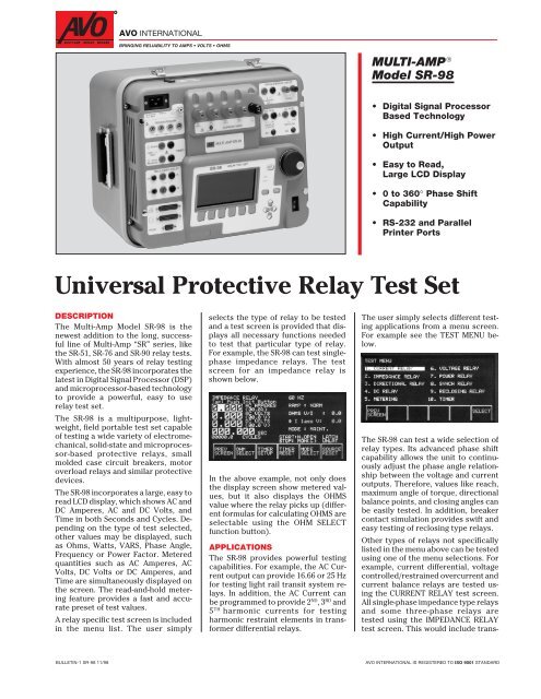
A relay specific test screen is included<br />
in the menu list. The user simply<br />
selects the type of relay to be tested<br />
and a test screen is provided that displays<br />
all necessary functions needed<br />
to test that particular type of relay.<br />
For example, the SR-98 can test singlephase<br />
impedance relays. The test<br />
screen for an impedance relay is<br />
shown below.<br />
In the above example, not only does<br />
the display screen show metered values,<br />
but it also displays the OHMS<br />
value where the relay picks up (different<br />
formulas for calculating OHMS are<br />
selectable using the OHM SELECT<br />
function button).<br />
APPLICATIONS<br />
The SR-98 provides powerful testing<br />
capabilities. For example, the AC Current<br />
output can provide 16.66 or 25 Hz<br />
for testing light rail transit system relays.<br />
In addition, the AC Current can<br />
be programmed to provide 2 ND , 3 RD and<br />
5 TH harmonic currents for testing<br />
harmonic restraint elements in transformer<br />
differential relays.<br />
The user simply selects different testing<br />
applications from a menu screen.<br />
For example see the TEST MENU below.<br />
The SR-98 can test a wide selection of<br />
relay types. Its advanced phase shift<br />
capability allows the unit to continuously<br />
adjust the phase angle relationship<br />
between the voltage and current<br />
outputs. Therefore, values like reach,<br />
maximum angle of torque, directional<br />
balance points, and closing angles can<br />
be easily tested. In addition, breaker<br />
contact simulation provides swift and<br />
easy testing of reclosing type relays.<br />
Other types of relays not specifically<br />
listed in the menu above can be tested<br />
using one of the menu selections. For<br />
example, current differential, voltage<br />
controlled/restrained overcurrent and<br />
current balance relays are tested using<br />
the CURRENT RELAY test screen.<br />
All single-phase impedance type relays<br />
and some three-phase relays are<br />
tested using the IMPEDANCE RELAY<br />
test screen. This would include trans-<br />
BULLETIN-1 SR-98 11/98 AVO INTERNATIONAL IS REGISTERED TO ISO 9001 STANDARD
MULTI-AMP SR-98<br />
mission line protection and loss of<br />
field type relays. The SYNCH RELAY<br />
<strong>Test</strong> Screen is used to test synchronizing<br />
and sync check relays.<br />
The Metering Screen provides powerful<br />
multi-purpose metering functions.<br />
Values like Volts, Amperes, Phase<br />
Angle, Power, Reactive Power and<br />
Power Factor are all simultaneously<br />
displayed.<br />
1 - Interface port for computer<br />
2 - Interface port for another SR-98<br />
or Models PVS/EPS-1000 threephase,<br />
phase shifters<br />
3 - Interface port for printer<br />
4 - Reset fuses for the circuit<br />
breaker simulator circuit<br />
5 - Normally Closed/Open contacts<br />
for the circuit breaker simulator<br />
circuit<br />
6 - Timer Start and Stop Gates<br />
7 - Resistor bank<br />
8 - Power input terminal<br />
9 - Fuses associated with<br />
power input<br />
8<br />
7<br />
6<br />
5<br />
4<br />
3<br />
2<br />
1<br />
FEATURES AND BENEFITS<br />
• Large variable contrast LCD display<br />
screen - Easy to read, no interpolation<br />
of analog meter scales. This saves time<br />
in testing relays and reduces human<br />
error.<br />
• Display screen prompts operator -<br />
The display screen prompts the user<br />
with easy to understand and use function<br />
keys. Single button operation<br />
saves time in testing relays and reduces<br />
human error.<br />
10 - Ground terminal associated<br />
with power input<br />
11 - Main current output terminals<br />
12 - On lamp for main current output<br />
terminals<br />
13 - External voltage and current<br />
measurement terminals<br />
14 - AC, (AUX) voltage output<br />
terminals<br />
15 - DC, (AUX) voltage output<br />
terminals<br />
16 - Control switches associated<br />
with AC, DC (AUX) voltage<br />
outputs<br />
10 9 11 12 13<br />
20 21<br />
24 25 26<br />
• Display screen provides five different<br />
languages - The display screen<br />
prompts the user in English, Spanish,<br />
Portuguese, French and German.<br />
• Output current and voltage<br />
sinewaves are generated digitally -<br />
Outputs do not vary with sudden<br />
changes in input voltage or frequency,<br />
which increases test Accuracy and<br />
saves testing time.<br />
17 - System reset button<br />
18 - Control knob<br />
19 - Power on switch<br />
20 - LCD display screen<br />
21 - Alarm reset switch<br />
22 - TRIP LED lamp<br />
23 - SYNC LED lamp<br />
24 - Initiate switch<br />
25 - Print Screen button<br />
26 - Associated with the up/down,<br />
right/left cursor keys<br />
14<br />
15<br />
16<br />
17<br />
18<br />
22<br />
23<br />
19
• Memory hold metering - Allows the<br />
user to set test currents and voltages<br />
faster. Reduces heating of device under<br />
test.<br />
• AC/DC voltage outputs can be operated<br />
independently of AC current<br />
output - Can provide DC logic voltage<br />
to solid-state relays prior to applying<br />
simulated fault current. This also allows<br />
users to test voltage controlled/<br />
restraint overcurrent relays without<br />
blocking voltage element contacts<br />
closed eliminating the need for elaborate<br />
test circuit connections and purchasing<br />
a separate DC voltage source<br />
or using station battery.<br />
• Timer has independent Start and<br />
Stop Gates - Perform timing functions<br />
independent of relay test set operation.<br />
Eliminates the need to purchase<br />
a separate timer for timing circuit<br />
breakers.<br />
• Current Accurate mode - Multipurpose<br />
test set capable of testing<br />
small molded-case circuit breakers<br />
and motor overload relays commonly<br />
found in industrial applications.<br />
• Interface port - Provides interface<br />
to other SR-98’s or AVO Phase Shifters.<br />
The SR-98 unit can be used with another<br />
SR-98 to test slope and harmonic<br />
restraint characteristics on current<br />
differential relays. The SR-98 unit can<br />
also be used with a three-phase phase<br />
shifter to test complex three-phase relays.<br />
This saves time in making test<br />
connections and the multi-purpose<br />
test system saves money.<br />
• Phase shift capability (0 to 359.9°) -<br />
The SR-98 provides phase shift between<br />
the main AC current and auxiliary<br />
AC voltage outputs (for testing<br />
complex relays) or between the 230<br />
volt output terminal of the main AC<br />
current and the auxiliary AC voltage<br />
outputs (for testing synchronizing relays).<br />
• Selectable output frequencies - The<br />
output frequency of the AC main current<br />
can be set for 16.66, 25 Hz (for<br />
testing light rail transit relays); 50, 60<br />
Hz (standard power frequency); 100,<br />
120, 150, 180, 250 and 300 Hz (for testing<br />
harmonic restraint on transformer<br />
differential relays). Multi-purpose test<br />
system saves time and money.<br />
• Circuit breaker simulator - Normally<br />
closed and normally open<br />
contacts are provided to simulate<br />
breaker operation for testing reclosing<br />
relays. Sequence of operation, timing,<br />
and lockout are easily tested.<br />
• Non-volatile RAM - Provides<br />
storage of special test set-up screens.<br />
• RS-232 and parallel printer ports -<br />
The RS-232 port provides for computer<br />
interface. The parallel printer port<br />
allows user to easily print test results.<br />
• <strong>Universal</strong> input voltage - Models<br />
SR98-1 and SR98-2 can use virtually<br />
any standard source in the world. The<br />
Model SR98-3 is designed for 230 Volt<br />
operation only.<br />
SPECIFICATIONS<br />
Input Power<br />
Model Numbers SR98-1/60 and<br />
SR98-2/50: 90 to 253 Volts AC, 1φ, 50/<br />
60 Hz, 1500 VA Max.<br />
Model Number SR98-3/50: 230 Volts<br />
AC, ±10%, 1φ, 50/60 Hz, 1500 VA Max.<br />
Outputs<br />
Three independently controlled,<br />
adjustable outputs are available<br />
from the test set; one AC current,<br />
one AC voltage and one DC voltage/<br />
current. All outputs are independent<br />
from sudden changes in line<br />
voltage and frequency. This provides<br />
stable outputs not effected<br />
by sudden changes in the source<br />
which is a common problem with<br />
traditional transformer loads.<br />
Selectable Output Frequencies<br />
The output frequency of the AC<br />
Main Current and AC AUX voltage<br />
can be set for 16.66, 25, 50, 60, 100,<br />
120, 150, 180, 250 and 300 Hz .<br />
AC Main Output Current<br />
The AC Main Current output is rated<br />
for 920 VA with four different output<br />
terminals for better impedance<br />
matching to the load. Outputs are<br />
continuously adjustable in the<br />
following Ranges:<br />
Output Current Full Load Voltage<br />
0 - 4 Ampres 230 Volts<br />
0 - 10 Ampres 90 Volts<br />
0 - 45 Ampres 20 Volts<br />
0 - 115 Ampres 8 Volts<br />
Output Current Duty Cycle<br />
At full rated output, maximum time<br />
on is 3 minutes followed by 20 minutes<br />
off. Duty is reduced to 1 minute<br />
on and 20 minutes off at an ambient<br />
temperature of 122° F (50° C) [1].<br />
AC Voltage Output<br />
The AC AUX voltage output is independently<br />
controlled and may be<br />
phase shifted relative to the Main<br />
AC Current/Voltage outputs. The<br />
SR-98 provides 0 to 359.9° phase<br />
shift between the Main AC Current<br />
and AC Auxiliary voltage outputs<br />
(for testing complex relays) or between<br />
the 230 volt output terminal<br />
of the Main AC Current and AC Auxiliary<br />
voltage outputs (for testing<br />
synchronizing relays).<br />
MULTI-AMP SR-98<br />
Output Voltage Current Rating<br />
0 - 300 Volts 0.25 Amp (AC AUX)<br />
0 - 230 Volts 4 Amp<br />
(AC CURRENT MAIN)<br />
DC Voltage/Current Output<br />
(Switch Selected)<br />
Output Voltage Current Rating<br />
0 - 240 Volts 0.4 Amp<br />
Output Current Voltage Rating<br />
0 - 2.5 Amps 12 Volts<br />
AC/DC Output Voltage Duty Cycle<br />
30 Minutes on followed by 30 minutes<br />
off.<br />
Metering<br />
Measured quantities such as AC Amperes,<br />
AC Volts, DC Volts or DC<br />
Amperes, and Time are simultaneously<br />
displayed on the large<br />
variable contrast LCD screen. The<br />
read-and-hold feature of the metering<br />
provides fast and accurate<br />
preset of test values. The AC Amperes<br />
also displays a percent of<br />
rotation when rotating the control<br />
knob for easy reference by the user.<br />
The AC and DC Volts display the<br />
approximate voltage output prior to<br />
initiation of the voltage outputs. This<br />
provides a fast, easy method for preset<br />
of voltage outputs. As a safety<br />
feature, the SR-98 alerts the user to<br />
the expected voltage output prior to<br />
turning on the voltage outputs.<br />
Other values which may be displayed<br />
depending on which test<br />
screen is in view are Phase Angle,<br />
Power, Reactive Power and Power<br />
Factor. Maximum current, external<br />
measurement mode is 6 Amperes<br />
AC or DC. Maximum voltage, external<br />
measurement mode is 600 Volts<br />
AC or DC. The large characters and<br />
variable contrast make the display<br />
easy to read from 3 to 4 feet (1 meter)<br />
away, even in direct sunlight. All<br />
Accuracy stated below are from 10<br />
to 100% of the range at 50/60 Hz.<br />
AC Amperes (Auto Ranging)<br />
Ranges and Resolution<br />
0 to 1.999/19.99/199.9 Amperes<br />
Accuracy: ±1% of reading<br />
Measurements: True RMS<br />
AC Volts (Auto Ranging)<br />
Ranges and Resolution 0 to 1.999/<br />
19.99/199.9/999.9 Volts<br />
Accuracy: ±1% of reading<br />
Measurements: True RMS<br />
DC Volts (Auto Ranging)<br />
Ranges and Resolution 0 to 1.999/<br />
19.99/199.9/ 999.9Volts<br />
Accuracy: ±1% of reading<br />
Measurements: Average
MULTI-AMP SR-98<br />
DC Amperes (Auto Ranging)<br />
Ranges and Resolution 0 to 1.999/<br />
19.99 Amperes<br />
Accuracy: ± 1 % of reading<br />
Measurements: Average<br />
Phase Angle<br />
Ranges and Resolution 0 to 359.9°<br />
Accuracy: ± 0.5°<br />
Power Factor<br />
Ranges and Resolution -0.99 to<br />
+0.99, with 0.01 resolution<br />
Accuracy: ± 0.02<br />
Power (Auto Ranging)<br />
Ranges and Resolution 0 to 4 kW in<br />
6 Ranges, with 0.1 % resolution<br />
Accuracy: ±1.5 % of VA ±1 least significant<br />
digit<br />
Reactive Power (Auto Ranging)<br />
Ranges and Resolution 0 to 4 kVAR<br />
in 6 Ranges, with 0.1 % resolution<br />
Accuracy: ±1.5 % of VA ±1 least significant<br />
digit<br />
Timer<br />
Range and Resolution: Displays in<br />
Seconds and Cycles, with the following<br />
range and resolution:<br />
Seconds: 0.0001 to 99999.9<br />
(Auto Ranging)<br />
Cycles: 0.01 to 99999.9<br />
(Auto Ranging)<br />
Accuracy: ±1 least significant digit or<br />
±.005% of reading, whichever is<br />
greater.<br />
Start/Stop/Monitor Gates:<br />
Two identical, independent, Start/<br />
Stop or Monitor Gate circuits are<br />
provided. To monitor operation of<br />
relay contacts or trip SCR, a continuity<br />
light is provided for the Stop<br />
gate. Upon sensing continuity the<br />
monitor lamp will glow and a tone<br />
generator will sound. The following<br />
modes are provided for the Start,<br />
Stop/Monitor Gates:<br />
1. Timer will start/stop or continuity<br />
indicator darkens at the opening<br />
of normally closed contacts or when<br />
conduction through a semiconductor<br />
device such as a triac is<br />
interrupted.<br />
2. Timer will start/stop or continuity<br />
indicator glows at the closing of<br />
normally open contacts or upon<br />
conduction through a semiconductor<br />
device such as a triac or<br />
transistor.<br />
3. Timer will start/stop or continuity<br />
indicator glows or darkens upon<br />
the application or removal of either<br />
an AC or DC voltage (60 to 300 V AC),<br />
(5 to 300 V DC). The maximum voltage<br />
to be applied is 300 Volts AC or<br />
DC.<br />
4. Starting or Stopping with any selected<br />
output. The Timer can be<br />
started or stopped when turning on<br />
or off selected outputs.<br />
5. In the Current Accurate Mode,<br />
the Timer stops when output current<br />
is interrupted.<br />
Start Latch:<br />
The Timer Start Gate is provided<br />
with a latch feature which allows<br />
timing to be initiated by a Start Gate<br />
and be stopped only by the selected<br />
Stop Gate. When unlatched, the<br />
Start Latch allows timing to be<br />
stopped when the Start Gate is reversed<br />
(such as when timing the<br />
closing and opening of a single contact<br />
as in measuring the trip-free<br />
operating time of a circuit breaker).<br />
Stop Latch:<br />
The Timer Stop Gate latch feature<br />
which allows timing to be stopped<br />
at the first operation of any Stop<br />
Gate (thus ignores contact bounce).<br />
When unlatched, the Stop Latch allows<br />
timing to be stopped by any<br />
Stop Gate and then restarted if the<br />
Stop Gate reverses (provided a Start<br />
Gate is still energized), and then<br />
stopped again when the gate reverses<br />
(total time including contact<br />
bounce).<br />
Protection<br />
Input and outputs are protected<br />
from short circuits and prolonged<br />
overloads.<br />
Ancillary Interface:<br />
A voltage signal output in phase with<br />
the main current output (±3°) is provided<br />
for use with the Multi-Amp<br />
Models EPS-1000 or PVS-1000 for<br />
phase reference. This will allow<br />
testing of more complex relays<br />
which require phase shifting<br />
between a three-phase voltage<br />
output (EPS-1000) and a current<br />
output (SR-98).<br />
Temperature Range<br />
Operating: 32 to 122° F (0 to 50° C)<br />
[1] Reduced duty cycle: Duty cycle is<br />
linearly de-rated from 3 minutes on,<br />
starting at 104° F (40° C) to 1 minute<br />
on at 122° F (50° C), followed by 20<br />
minutes off.<br />
Storage: -40 to 158° F (-40 to 70° C)<br />
Relative Humidity: 90% RH, Noncondensing<br />
Enclosure<br />
The unit comes mounted in a rugged<br />
plastic transit case for field<br />
portability. The tongue and groove<br />
lid protects the unit from rain and<br />
dust intrusion. Spring loaded carrying<br />
handles are located on each side<br />
for carry convenience.<br />
Dimensions<br />
Unit Enclosure<br />
17.75 H x 16.5 W x 15.5 D in.<br />
444 H x 416 W x 387 D mm<br />
Weight: 52.5 lb. (23.6 kg) cover lid on<br />
49.3 lb. (22.2 kg) cover lid off
ORDERING INFORMATION<br />
MULTI-AMP SR-98<br />
Item (Qty) Cat. No.<br />
Model SR-98, with 90 to 253 Volts input<br />
Output frequency preset to 60 Hz, North American power cord ............................................................................ SR98-1/60<br />
Output frequency preset to 50 Hz, International color coded line cord ................................................................ SR98-2/50<br />
Model SR-98, with 230 Volt input<br />
Output frequency preset to 50 Hz, Continental Europe line cord........................................................................... SR98-3/50<br />
Included Accessories<br />
Line cord, North American (Model SR98-1/60) (1 ea)............................................................................................................. 14350<br />
Line cord, Continental Europe (Model SR98-3/50) (l ea) ........................................................................................................ 15021<br />
Line cord, International (Model SR98-2/50 ) (1 ea) .................................................................................................................. 14525<br />
Instruction manual (1 ea) ............................................................................................................................................................ 51187<br />
15 A Input fuse, (for 120 Volt input) (5 ea) T rated ..................................................................................................................... 963<br />
8 A Input Fuse, (230 Volt input) (5 ea) T rated ............................................................................................................................ 962<br />
<strong>Test</strong> lead, red, 200 cm, use with voltage outputs and timer (3 ea) CAT II .............................................................................16242<br />
<strong>Test</strong> lead, black, 200 cm, use with voltage outputs and timer (3 ea) CAT II .........................................................................16243<br />
Lug adapter, red, 6.2 mm, use with voltage outputs and timer (2 ea) CAT II........................................................................15932<br />
Lug adapter, black, 6.2 mm, use with voltage outputs and timer (2 ea) CAT II ....................................................................15927<br />
Lug adapter, red, 4.1 mm, use with voltage outputs and timer (2 ea) CAT II........................................................................15933<br />
Lug adapter, black, 4.1 mm, use with voltage outputs and timer (2 ea) CAT II ....................................................................15928<br />
Alligator clip, red, use with voltage outputs and timer (1 ea) CAT II .....................................................................................16238<br />
Alligator clip, black, use with voltage outputs and timer (1 ea) CAT II .................................................................................16240<br />
<strong>Test</strong> leads, red/blk, use with current output (includes spades) (1 pr) CAT II ........................................................................7934<br />
Optional Accessories<br />
#4 High current test leads, 5 ft. [1.5 m] (1 pr), use when testing molded case breakers ...................................................... 2265<br />
For three-phase applications, an optional Phase Angle Meter (PAM) interface cable is required<br />
to interface the SR-98 to Multi-Amp three-phase phase shifters.<br />
Cable, interface, for models EPS-1000 and PVS-1000 (1ea) ............................................................................................. 51680<br />
Cable, interface, Master/Slave, for SR-98 to SR-98 (1ea) .................................................................................................. 51679
MULTI-AMP SR-98<br />
UNITED STATES<br />
EXPORT<br />
CANADA<br />
4651 S. WESTMORELAND ROAD AVO INTERNATIONAL<br />
110 MILNER AVENUE, UNIT 1<br />
DALLAS, TX 75237-1017 USA<br />
4651 S. WESTMORELAND ROAD SCARBOROUGH, ON M1S 3R2<br />
PHONE: (800) 723-AVO-1 (723-2861) DALLAS, TX 75237-1017 USA CANADA<br />
FAX: (214) 333-3533 PHONE: (214) 331-7363<br />
FAX: (214) 337-3038<br />
PHONE: (800) 567-0-AVO (567-0286)<br />
FAX: (416) 298-7214<br />
© 1998 AVO INTERNATIONAL PRINTED IN USA<br />
MIL/1.5M/1198 AVO-1095 BULLETIN-1 SR-98