Visible Light Communication for Advanced Driver Assistant Systems
Visible Light Communication for Advanced Driver Assistant Systems
Visible Light Communication for Advanced Driver Assistant Systems

You also want an ePaper? Increase the reach of your titles
YUMPU automatically turns print PDFs into web optimized ePapers that Google loves.
<strong>Visible</strong> <strong>Light</strong> <strong>Communication</strong> <strong>for</strong> <strong>Advanced</strong> <strong>Driver</strong> <strong>Assistant</strong> <strong>Systems</strong><br />
Navin Kumar † , Luis Alves Nero †¥ , Rui L. Aguiar †¥<br />
† Instituto de Telecomunicações, Aveiro, Portugal<br />
Phone: +351-234377900, Fax: +351-234377901, e-mail: kumar@av.it.pt<br />
¥ Universidade de Aveiro, Campo Universitário, 3810-193 Aveiro, Portugal<br />
email: nero@ua.pt, ruilaa@ua.pt<br />
Abstract 1 — VIsible light communication <strong>for</strong> advanced <strong>Driver</strong><br />
<strong>Assistant</strong> <strong>Systems</strong> (VIDAS) is an outdoor application using the<br />
visible spectrum of light emitting diodes (LED). A simple traffic<br />
light set up based on LED traffic lights <strong>for</strong> traffic in<strong>for</strong>mation<br />
transmission has been analyzed in this paper. Various important<br />
design parameters have been optimized through intensive<br />
investigation based on gain variation over 100 m of transmission<br />
range. This process is expected to simplify the front-end receiver<br />
design and enhance the per<strong>for</strong>mance of the receiver which is one<br />
of the most critical elements in a visible light communication<br />
(VLC) transceiver, especially in outdoor applications. Our design<br />
results show receiver adaptability <strong>for</strong> different packet sizes and<br />
different distances.<br />
Keywords: HB-LEDs, VIDAS, VLC, wireless optical<br />
communication.<br />
I. INTRODUCTION<br />
<strong>Visible</strong> <strong>Light</strong> <strong>Communication</strong> <strong>Systems</strong> are a novel kind<br />
of optical wireless communication, using white and coloured<br />
LEDs. The use of visible light as a communication medium is<br />
still at a very early stage, compared to what has been<br />
achieved in areas like infrared and laser (free space optics).<br />
The VLC system using LEDs as light sources has many<br />
distinctive features and high potential to be a ubiquitous<br />
communication system. The VLC system is expected to<br />
undergo rapid progress, inspiring numerous indoor and<br />
outdoor applications. With recent advancement in high power<br />
coloured and white LEDs, the advantages of Infrared (IR)<br />
technology can be explored by VLC systems. In this system<br />
white and coloured LEDs can be used <strong>for</strong> data transmission<br />
[1,2] and at the same time provide lighting and signalling<br />
functionalities.<br />
White and Coloured LED and High Brightness LEDs<br />
(HB-LEDs) devices are being used in large scale in indoor<br />
lighting, full colour displays, traffic lights, car lights etc.<br />
Fortunately, an intrinsic characteristic of LED is that it is a<br />
semiconductor, with high rate switching capabilities, making it<br />
possible to extend its usage to data transfer in wireless<br />
communications systems. These dual properties make them<br />
The work is a part of FCT project VIDAS – PDTC/EEA-TEL/75217/2006<br />
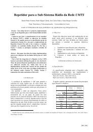
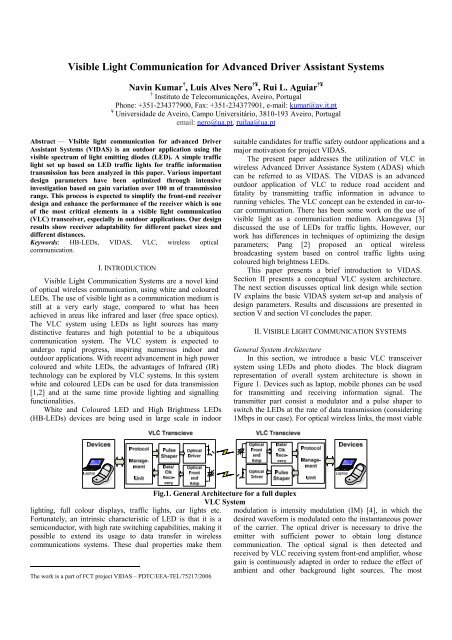
Fig.1. General Architecture <strong>for</strong> a full duplex<br />
VLC System<br />
suitable candidates <strong>for</strong> traffic safety outdoor applications and a<br />
major motivation <strong>for</strong> project VIDAS.<br />
The present paper addresses the utilization of VLC in<br />
wireless <strong>Advanced</strong> <strong>Driver</strong> Assistance System (ADAS) which<br />
can be referred to as VIDAS. The VIDAS is an advanced<br />
outdoor application of VLC to reduce road accident and<br />
fatality by transmitting traffic in<strong>for</strong>mation in advance to<br />
running vehicles. The VLC concept can be extended in car-tocar<br />
communication. There has been some work on the use of<br />
visible light as a communication medium. Akanegawa [3]<br />
discussed the use of LEDs <strong>for</strong> traffic lights. However, our<br />
work has differences in techniques of optimizing the design<br />
parameters; Pang [2] proposed an optical wireless<br />
broadcasting system based on control traffic lights using<br />
coloured high brightness LEDs.<br />
This paper presents a brief introduction to VIDAS.<br />
Section II presents a conceptual VLC system architecture.<br />
The next section discusses optical link design while section<br />
IV explains the basic VIDAS system set-up and analysis of<br />
design parameters. Results and discussions are presented in<br />
section V and section VI concludes the paper.<br />
II. VISIBLE LIGHT COMMUNICATION SYSTEMS<br />
General System Architecture<br />
In this section, we introduce a basic VLC transceiver<br />
system using LEDs and photo diodes. The block diagram<br />
representation of overall system architecture is shown in<br />
Figure 1. Devices such as laptop, mobile phones can be used<br />
<strong>for</strong> transmitting and receiving in<strong>for</strong>mation signal. The<br />
transmitter part consist a modulator and a pulse shaper to<br />
switch the LEDs at the rate of data transmission (considering<br />
1Mbps in our case). For optical wireless links, the most viable<br />
modulation is intensity modulation (IM) [4], in which the<br />
desired wave<strong>for</strong>m is modulated onto the instantaneous power<br />
of the carrier. The optical driver is necessary to drive the<br />
emitter with sufficient power to obtain long distance<br />
communication. The optical signal is then detected and<br />
received by VLC receiving system front-end amplifier, whose<br />
gain is continuously adapted in order to reduce the effect of<br />
ambient and other background light sources. The most
practical down-conversion technique is direct detection (DD).<br />
The modulation method used must offer high robustness to<br />
background light. Similarly, the detector is characterized by<br />
the parameter, field of view (FOV). For a larger service area,<br />
a receiver with a wider FOV is preferable. However, a wider<br />
FOV leads to per<strong>for</strong>mance degradation because all received<br />
signals, including mostly undesired signals, are processed<br />
simultaneously.<br />
In addition the system will also need the protocol<br />
management unit and data/clock recovery block <strong>for</strong> the<br />
synchronization of received packets corresponding to the<br />
received power level.<br />
The data rate in VLC systems is limited by the switching<br />
speed of LEDs transmitter. In the outdoor environment, such<br />
as VIDAS our aim is to develop a prototype VLC system able<br />
to transmit, with a data rate of 1Mbps and showing BER<br />
smaller than 10 -6 . Long distance communication in this case is<br />
limited by the transmitted power and background light<br />
sources.<br />
III. DESIGNING THE OPTICAL LINK FOR VIDAS<br />
Designing a VLC system is multidisciplinary task as<br />
discussed be<strong>for</strong>e. Optical channel poses severe restrictions to<br />
system components such as necessary optical power and the<br />
necessary sensitivity and input dynamic range of the receiver<br />
front-end. Achieving high signal to noise ratio (SNR) is very<br />
challenging. High emitter power can not be considered<br />
because of power consumption and safety related issue. The<br />
receiver should have large light-collection area to minimize<br />
the path loss. At the same time it must be able to reduce the<br />
effect of intense ambient light and other noise source.<br />
A. LEDs Emitter<br />
LEDs traffic light consists of set of LEDs closely wired<br />
to fit into the standard traffic light dimension of 200mm or<br />
300mm. Typically LEDs with half power angle (hpa) of 15º<br />
to 45º are used. The emitter is modelled using a generalized<br />
Lambertian radiation pattern (Re(φ,m))[4]. This assumption<br />
allows the modelization of all single-lobe symmetrical<br />
emitters. ‘m’ is the mode number of the radiation lobe, which<br />
specifies the directivity of the emitter and is given by the hpa:<br />
−ln<br />
2<br />
m = (1)<br />
ln(cos( hpa))<br />
Assuming that Pt is the transmitted power, the radiation<br />
intensity is given by:<br />
m + 1 m ⎡− π π ⎤<br />
R E ( ϕ,<br />
m)<br />
= Pt<br />
cos ( ϕ);<br />
ϕ ∈ ⎢ ,<br />
2π<br />
⎥ (2)<br />
⎣ 2 2 ⎦<br />
Figure 2 below shows the polar plot <strong>for</strong> different mode<br />
number of the radiation lobe. It is seen that as ‘m’ increases<br />
the directivity of radiation increases.<br />
B. The Detector and Front End Amplifier<br />
At the receiver a PIN photodiode converts the optical<br />
signal into an electrical current, which is further amplified by<br />
a front-end amplifier. In a LOS case, the influence of the<br />
directed light is very large which determines mainly the<br />
Fig.2. Radiation pattern as a function of ‘m’ and ‘φ’<br />
per<strong>for</strong>mance of the system. A bare detector achieves an<br />
effective signal-collection area of<br />
⎪⎧<br />
Ad<br />
cos( σ ) ; σ < FOV<br />
Aeff<br />
( σ ) = ⎨<br />
(3)<br />
⎪⎩ 0 ; σ ≥ FOV<br />
where Ad is the detector physical area and σ is the angle of<br />
incidence with respect to the receiver axis.<br />
The generated photocurrent consists of desired signal<br />
current (proportional to the incident optical power); and noise<br />
component mostly dominated by shot noise current. Noise<br />
contributions are out of the scope of this work. However,<br />
future work will address noise problems and receiver frontend<br />
design in more details.<br />
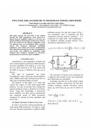
In order to meet the requirements of high sensitivity, gain<br />
and higher dynamic range transimpedance amplifiers (TIA)<br />
with switched feedback network or controlled feedback<br />
scheme as shown in fig. 3(a) and (b) are suitable candidates<br />
<strong>for</strong> the front-end receiver. In the design considerations of<br />
front-end the trade off between gain and dynamic range plays<br />
an important role.<br />
There are two quantities which bound the dynamic input<br />
range: i) the front-end sensitivity - the minimum signal that<br />
can be recognized considering the presence of noise; and ii)<br />
the maximum output signal <strong>for</strong> which the front-end still<br />
exhibits an approximately linear response. The control circuit<br />
acts proportionally to the signal level, varying a set of<br />
multiple feedback resistors in order to obtain an easily<br />
controlled gain. This control scheme operates in such a way<br />
that it is effectively outside the signal path <strong>for</strong> the largest<br />
gains, achieving the lowest internal noise <strong>for</strong> very low input<br />
signals.<br />
IV. TRAFFIC SYSTEM SET- UP FOR VIDAS<br />
A simple system set-up of VLC <strong>for</strong> VIDAS is shown in<br />
Figure 4. The LED traffic light emitter is placed at height h<br />
above ground. The detector is moving towards the emitter<br />
with certain speed. The half-power semi angle of LED is 15º.<br />
The receiver is installed on the centre of the vehicle front<br />
panel, and it has a vertical inclination of ‘Ѳ’ and FOV. We<br />
assume LOS link between the first receiver and LED traffic<br />
light transmitter. Umin and Umax is the range of possible<br />
communication with Umin being near to traffic point while<br />
Umax is the starting point from where receiver starts receiving<br />
the traffic in<strong>for</strong>mation. The involved system parameters are<br />
given in the table below:
Fig. 3 a) Switched gain strategy b) Controlled feedback strategy<br />
Table-I<br />
Height of the traffic light (m) h<br />
Distance between emitter and d<br />
receiver (m)<br />
Distance in first lane direction (m) x<br />
Service area [Umax,Umin]<br />
Half-power semiangle hpa = 15º<br />
Angle of Irradiance φ<br />
Vertical Inclination of Receiver 0≤Ѳ≤90º<br />
Field of View of receiver 0º≤FOVc≤90º<br />
Angle of incidence σ<br />
A. Channel Model<br />
For a LOS configuration the incident power collected by<br />
the photodiode at the receiver end, depends on the transmitted<br />
power, on the geometry of the system traffic light to car, on<br />
the channel attenuation and on the receiver model. A simple<br />
model [4] <strong>for</strong> optical communication can be considered. The<br />
LOS case received signal is there<strong>for</strong>e given by:<br />
m<br />
m + 1 cos ( ϕ)<br />
⎛ d ⎞<br />
I = P(<br />
t)<br />
Ad<br />
cos( σ ) ∂⎜t<br />
− ⎟ (4)<br />
2π<br />
2<br />
d<br />
⎝ c ⎠<br />
where d is distance between transmitter and receiver. The<br />
term ∂(t-d/c) is the delay due to channel propagation. The<br />
above equation (4) can be written as function of (x, θ, h, ø)<br />
and simple manipulation results in:<br />
⎛ m⎛π<br />
−1<br />
⎞ −1<br />
⎞<br />
⎜cos<br />
⎜ − tan ( x/<br />
h)<br />
−φ⎟cos(<br />
tan ( x/<br />
h)<br />
−θ)<br />
⎟<br />
( m+<br />
1)<br />
⎜ ⎝ 2<br />
⎠<br />
⎟<br />
Hn(<br />
φ , θ,<br />
x,<br />
h)<br />
=<br />
(5)<br />
⎜<br />
2 2<br />
2π<br />
⎟<br />
⎜<br />
h + x<br />
⎟<br />
⎝<br />
⎠<br />
Optimizing θ and ø and taking the weighted average of these<br />
function and plotting the power loss over the range of 100m<br />
distance, a loss of approximately 20 dB is noticed as can be<br />
seen in Figure 5.<br />
∫<br />
B. Construction of the Service Area<br />
Definition of service area (SA) and optimization of various<br />
parameters help in optimizing high per<strong>for</strong>mance front-end<br />
receiver. Let us assume: Data transmission rate (Rb =<br />
1Mbps); packet size (PS=100Kb); average velocity of the<br />
running vehicles (V=50km/h). Vehicles travel approximately<br />
1.39m of distance (call it as packet service area-PSA) which<br />
is equal to the time required to transmit one packet of data. It<br />
is also assumed that the data packet contains the same<br />
in<strong>for</strong>mation i.e. PS contains whole in<strong>for</strong>mation to be<br />
transmitted and it is repeated continuously.<br />
If the vehicle starts receiving in<strong>for</strong>mation from a distance<br />
of 100m from the traffic point in the first lane, we can notice<br />
the power variation in each PSA which is quite small, can be<br />
ignored. But in fact, as the vehicle approaches towards traffic<br />
light the power variation is considerable and the receiver must<br />
be able to adapt such variation to give necessary output. Since<br />
the PSA is very small, we can choose a larger unit of distance<br />
<strong>for</strong> the power variation over each 14m (10x1.39=approx<br />
14m) call it as frame service area (FSA). The measured<br />
variation of power over this distance is given in table-II:<br />
Table-II<br />
FSA 100- 86- 72- 58- 44- 30- 16-<br />
(m) 86 72 58 44 30 16 6<br />
dB 1.3 1.4 1.9 2.7 3.2 5 3.1<br />
Based on this in<strong>for</strong>mation, it is possible to design a receiver<br />
either <strong>for</strong> varying packet size over a distance unit or adjusting<br />
the gain keeping fixed packet size. We see a sharp variation at<br />
very close to traffic point which is because of restricted<br />
minimum distance of in<strong>for</strong>mation transmission. Since in the<br />
cases when vehicles stop at traffic point during red signal they<br />
maintain <strong>for</strong> certain distance of 3-4 m.<br />
V. RESULT AND DISCUSSION<br />
The above analysis is valid and true <strong>for</strong> a fixed PS of<br />
100kb and adjusting receiver gain with such variation may not<br />
be practical. To overcome this, we refine our algorithm and<br />
try to find a fixed gain <strong>for</strong> varying distance. The distance<br />
measured in the beginning from the point when vehicle starts<br />
receiving is much larger than that near the traffic light.<br />
FOV<br />
Fig.4. VLC scenario <strong>for</strong> VIDAS
Fig.5. Gain variation over the distance <strong>for</strong> different<br />
values of h and optimized Ѳ<br />
Fig.6. Service área vs gain <strong>for</strong> different values of<br />
traffic height ‘h’<br />
Alternatively it can also be said that the designed receivers<br />
should be capable of receiving different packet sizes over the<br />
distance which is given by:<br />
PSA*<br />
Rb<br />
PS = PSA*<br />
Rb<br />
(6)<br />
( ) ( )<br />
V<br />
The Figure 6 illustrates this. In addition to this the figure also<br />
represents plots <strong>for</strong> different values of the height of the traffic<br />
light. It is seen that the suitable height can be chosen from<br />
this results. It is a useful recommendation <strong>for</strong> future<br />
installation of LEDs based traffic light.<br />
Though the measured gain variation over the distance is<br />
not large (