pdf (9087 KB) - Electronic Visualization Laboratory - University of ...
pdf (9087 KB) - Electronic Visualization Laboratory - University of ...
pdf (9087 KB) - Electronic Visualization Laboratory - University of ...

Create successful ePaper yourself
Turn your PDF publications into a flip-book with our unique Google optimized e-Paper software.
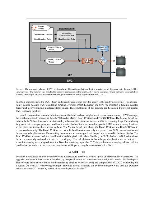
Figure 4. The rendering scheme <strong>of</strong> DVC is shows here. The pathway that handles the interleaving <strong>of</strong> the scene onto the rear LCD is<br />
shown in blue. The pathway that handles the linescreen rendering on the front LCD is shown in orange. These pathways represents how<br />
the autostereoscopic and parallax barrier rendering was abstracted in the original iteration <strong>of</strong> DVC.<br />
link their applications to the DVC library and pass it stereoscopic pairs for access to the rendering pipeline. This abstraction<br />
is desired because DVC’s rendering pipeline leverages OpenGL shaders and MPI 14 to maintain a dynamic parallax<br />
barrier and a corresponding interlaced stereo image. The complexities <strong>of</strong> this pipeline can be seen in Figure 4 illustrates<br />
DVC rendering pipeline.<br />
In order to maintain accurate autostereoscopy, the front and rear display must render synchronously. DVC manages<br />
the synchronization by managing three MPI threads : Master, RearLCDSlave, and FrontLCDSlave. The Master thread initializes<br />
the MPI shared memory variables and synchronizes the other two threads within its rendering loop. The rendering<br />
loop awaits stereoscopic pairs and head location data. Both <strong>of</strong> these are stored in specified MPI shared memory locations<br />
so the other two threads have access to them. The Master thread then allows the FrontLCDSlave and RearLCDSlave to<br />
render synchronously. The FrontLCDSlave accesses the head location data only and passes it to a GLSL shader to calculate<br />
the corresponding linescreen. The resulting linescreen is texture mapped onto a quad and rendered to the front display. The<br />
RearLCDSlave accesses both the head location and the pixel buffer data. Similarly, a GLSL shader is called to interleave<br />
the scene accurately and render it onto the rear display. The calculations for both the parallax barrier and the autostereo<br />
scene interleaving were adopted from the Dynallax rendering algorithm. 10 This synchronous rendering allows both the<br />
parallax barrier and the scene to update in real-time while preserving the autostereoscpoic effect.<br />
4. METHOD<br />
Dynallax incorporates a hardware and s<strong>of</strong>tware infrastructure in order to create a hybrid 2D/3D scientific workstation. The<br />
upgraded hardware infrastructure is described by the specifications and parameters for our dynamic parallax barrier display.<br />
The s<strong>of</strong>tware infrastructure builds on the rendering pipeline to abstract away the complexities <strong>of</strong> 2D/3D windowing via<br />
a custom OS level X11 windowing manager. The final display assembly can be seen in Figure 5 and uses the Dynallax<br />
method to create 3D images by means <strong>of</strong> a dynamic parallax barrier. 10