pdf (9087 KB) - Electronic Visualization Laboratory - University of ...
pdf (9087 KB) - Electronic Visualization Laboratory - University of ...
pdf (9087 KB) - Electronic Visualization Laboratory - University of ...

You also want an ePaper? Increase the reach of your titles
YUMPU automatically turns print PDFs into web optimized ePapers that Google loves.
4.2.3 Master thread : Gathering 2D Context<br />
In order to gather the correct information about the 2D contexts, the content <strong>of</strong> the Window array needs to be traveled,<br />
the 2D content must be moved to the read LCD, overlapping 2D content must have its information stored and<br />
then written to MPI shared memory. A for loop is used to traverse the Window array given the information received<br />
from XQueryTree(). The properties <strong>of</strong> each Window can be retrieved by calling either XGetGeometry( ) or<br />
XGetWindowAttributes(). All Windows located on the front LCD are moved by calling XMoveWindow(). Afterwards<br />
another pass is made through the array <strong>of</strong> Windows. This pass ignores all Windows matching geometries equal<br />
to the 3D areas defined by DVC. All others are checked to see whether it overlaps a 3D area. A 2D area overlaps if its Zdepth,<br />
is less than any 3D area. A Window’s Z-depth is determined by its locations within the Windows array. Therefore<br />
an overlapping 2D area will have a smaller index than the 3D area. 2D areas that overlap have their Windows properties<br />
retrieved and stored within MPI shared memory variables.<br />
4.2.4 FrontSlaveLCD thread : Clearing the Parallax Barrier<br />
The FrontLCDSlave thread manages the clearing <strong>of</strong> the linescreen based on the geometric information stored in MPI<br />
shared memory. The render loop <strong>of</strong> the FrontLCDSlave is primarily responsible for drawing the linescreen on the front<br />
LCD. This rendering is done via GLSL shaders by passing various arguments to the GPU that defined the properties <strong>of</strong><br />
the linescreen. To preserve visibility, the FrontLCDSlave was modified to also pass in geometric information stored in<br />
MPI shared memory. This information corresponds to overlapping 2D content. Due to the transparent nature <strong>of</strong> LCDs,<br />
modifying the shader to drawing a white rectangle over the linescreen was sufficient. This process allows original 2D<br />
s<strong>of</strong>tware to run unimpeded at native resolution. Additionally, since the update is done at each frame, 2D and 3D applications<br />
can be resized, moved, and switched in and out <strong>of</strong> focus seamlessly.<br />
5. RESULTS AND CASE STUDIES<br />
We evaluated our workstation by measuring optical parameters such as crosstalk and scattering. We then coupled Dynallax<br />
to three materials science applications that visualized isosurfaces, ball-and-stick models, and volume rendering.<br />
5.1 Optical Tests<br />
We evaluated the optical quality <strong>of</strong> the system using a variety <strong>of</strong> methods. The<br />
contrast ratio was measured as the difference between light emitting from both<br />
screens set to full white compared to both screens set to black, a ratio <strong>of</strong> 64:1.<br />
A test <strong>of</strong> light leakage from a white rear screen through a black front screen resulted<br />
in 2% leakage, or 98% opacity <strong>of</strong> a black front screen. We tested crosstalk<br />
using two methods; both resulted in a crosstalk ratio <strong>of</strong> 25%. The first method<br />
from Sandin et al. 13 measures the light levels in one eye channel set to black and<br />
one eye channel set to white, and computes the ratio <strong>of</strong> the black to the white<br />
intensity.<br />
The second method relies on digital photographs <strong>of</strong> the primary and<br />
crosstalk channels for a single eye position. By photographing the same image<br />
at different shutter speeds and comparing the results, we can find the faster shutter<br />
speed that reduces the primary channel to the same intensity as the crosstalk<br />
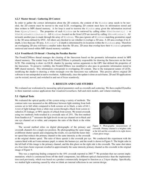
Figure 9. Photographic measurement <strong>of</strong><br />
crosstalk. Primary channel is a brighter cube<br />
at the left and the crosstalk to its right shows<br />
a faint ghost image.<br />
at the original shutter speed. The ratio <strong>of</strong> these speeds is the crosstalk per eye. We conducted this experiment with the<br />
camera fitted with an 8 mm entrance pupil, to mimic the human eye, and the result is shown in Figure 9. The bright cube in<br />
the left half <strong>of</strong> this image is the primary channel, and the dim ghost on the right side is the crosstalk. The same shot taken<br />
at a four times faster exposure resulted in approximately the same intensity primary channel as the crosstalk in the original<br />
image <strong>of</strong> Figure 9.<br />
This was a surprising finding compared to the 10% crosstalk reported in 2007. 10 We postulate that our current implementation,<br />
which is constructed from <strong>of</strong>f-the-shelf components, has different optical characteristics than the implementation<br />
used previously, which was based on a product commercially designed to function as a 2-layer display. Specifically,<br />
we studied light scattering caused by what we think are internal reflections in our current design.