

Hughes & Kettner MSM-1 User Manual - EXACT
Hughes & Kettner MSM-1 User Manual - EXACT
Hughes & Kettner MSM-1 User Manual - EXACT

Create successful ePaper yourself
Turn your PDF publications into a flip-book with our unique Google optimized e-Paper software.
<strong>Hughes</strong> & <strong>Kettner</strong> <strong>MSM</strong>-1 <strong>User</strong> <strong>Manual</strong><br />
Note: These instructions were written specifically for the <strong>Hughes</strong> & <strong>Kettner</strong> ATTAX preamp, but they apply equally to the MIDI-upgradeable<br />
amps from <strong>Hughes</strong> & <strong>Kettner</strong>: the TriAmp head and combo, the TUBE 50 head/combo and TUBE 100 head, the ATTAX 100 and ATTAX 200<br />
heads and combo amps, and the BassBase 600 head. More general installation instructions follow this document.<br />
Installation<br />
1. Connections and Control Features<br />
2. MIDI Functions<br />
3. Standard Setup and Cable Connections<br />
4. Short Instructions<br />
Operation<br />
1. Selecting MIDI Channels and the Omni Mode<br />
2. Storing Your Presets<br />
3. Activating Stored Presets via MIDI<br />
Additional MIDI Setups<br />
Troubleshooting<br />
INSTALLATION PROCEDURE: <strong>MSM</strong>-1 into the ATTAX PREAMP<br />
The ATTAX and the <strong>MSM</strong>-1 MIDI SWITCHING MODULE are electronic devices that operate on AC power. If you are not qualified to install the<br />
<strong>MSM</strong>-1, you are risking a potentially life-threatening electric shock. Do yourself a favor and ensure you leave the installation to an authorized<br />
dealer only, both a safety and a warranty requirement. It takes just a few minutes, and it is well worth waiting for.<br />
Proceed as follows:<br />
� Switch the ATTAX off.<br />
� Remove the AC mains power cord from the back of the unit.<br />
� Remove the four screws from rear panel cover plate and then remove the cover plate.<br />
� Remove the screws from the top of the chassis.<br />
� Lift the chassis cover off.<br />
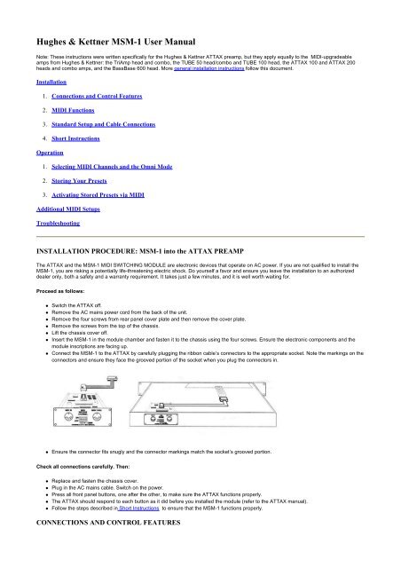
� Insert the <strong>MSM</strong>-1 in the module chamber and fasten it to the chassis using the four screws. Ensure the electronic components and the<br />
module inscriptions are facing up.<br />
� Connect the <strong>MSM</strong>-1 to the ATTAX by carefully plugging the ribbon cable’s connectors to the appropriate socket. Note the markings on the<br />
connectors and ensure they face the grooved portion of the socket when you plug the connectors in.<br />
� Ensure the connector fits snugly and the connector markings match the socket’s grooved portion.<br />
Check all connections carefully. Then:<br />
� Replace and fasten the chassis cover.<br />
� Plug in the AC mains cable. Switch on the power.<br />
� Press all front panel buttons, one after the other, to make sure the ATTAX functions properly.<br />
� The ATTAX should respond to each button as it did before you installed the module (refer to the ATTAX manual).<br />
� Follow the steps described in Short Instructions to ensure that the <strong>MSM</strong>-1 functions properly.<br />
CONNECTIONS AND CONTROL FEATURES
1. MIDI IN JACK<br />
The MIDI IN jack is designed to receive MIDI data. Any device capable of generating MIDI data can be connected here via its MIDI OUT jack. In<br />
most cases, a MIDI FOOT CONTROLLER or MIDI EFFECTS UNIT is the device you will use.<br />
2 MIDI THRU JACK<br />
The MIDI THRU jack is used if you want to relay incoming MIDI messages to an additional MIDI device, e.g. an effects processor. Simply<br />
connect the device’s MIDI IN to the <strong>MSM</strong>-1 's MIDI THRU. This enables you to address the ATTAX and one or more additional devices via a<br />
single MIDI command.<br />
3 MIDI RECEIVE CHANNEL SWITCH<br />
This five-way DIP switch determines on which MIDI channels the <strong>MSM</strong>-1 receives MIDI messages. You can select a single CHANNEL (1<br />
through 16), or all MIDI CHANNELS at once.<br />
MIDI LEARN BUTTON (front panel)<br />
The MIDI LEARN BUTTON on the ATTAX front panel is operable after the <strong>MSM</strong>-1 is installed, and is used to assign ATTAX channel/effects<br />
combinations to various memory locations.<br />
MIDI FUNCTIONS<br />
MIDI is the abbreviation for Musical Instrument Digital Interface. MIDI is an international standard in which musical information, to include sound<br />
parameter changes, is translated to digital data and sent to various instruments, e.g. amps, effects devices, keyboards, etc.<br />
The <strong>MSM</strong>-1 can process MIDI commands containing sound changes, i. e. messages that change the ATTAX channel/effects loop settings.<br />
These commands are referred to as MIDI PROGRAM CHANGE MESSAGES. They consist of a MIDI CHANNEL NUMBER and a MIDI<br />
PROGRAM number.<br />
MIDI CHANNEL NUMBER<br />
A typical guitar rack can contain several MIDI capable devices. You must assign each device a specific MIDI CHANNEL NUMBER to ensure the<br />
message is addressed to the right device. 16 MIDI CHANNELS (1 through 16) are available. For instance, if you assign MIDI CHANNEL<br />
NUMBER 7 to the <strong>MSM</strong>-1 (refer to Section 2.1), then the module reacts exclusively to commands addressed to MIDI CHANNEL 7.<br />
OMNI MODE<br />
If you want to address several devices in your rack simultaneously, switch on the OMNI MODE for each device. All devices will then ignore the<br />
MIDI CHANNEL NUMBERS and respond to MIDI commands on all CHANNELS. Refer to Section 2.1 for information on how to select the <strong>MSM</strong>-<br />
1 OMNI MODE.<br />
EXAMPLE<br />
The <strong>MSM</strong>-1 is set to MIDI CHANNEL 3. A MIDI command containing a "MIDI CHANNEL 3/PROGRAM NUMBER 17" message is sent. The<br />
<strong>MSM</strong>-1 responds by activating the channel and effects loop combination saved on preset 17.<br />
STANDARD SET-UP / CABLE CONNECTIONS
INSTRUCTIONS - THE SHORT FORM 1.4<br />
OPERATING THE ATTAX VIA MIDI<br />
SELECTING MIDI CHANNELS AND THE OMNI MODE<br />
Use the five-way DIP switch to select the MIDI CHANNEL and the OMNI MODE. Switch settings 1-4 determine the MIDI CHANNEL; the fifth<br />
switch is the OMNI OFF/ON switch. The OMNI ON setting ensures the ATTAX receives MIDI data on all MIDI CHANNELS, regardless of how
switches 1-4 are set.<br />
Note: Ensure the OMNI switch is set to OFF when you want the ATTAX to receive MIDI data on a single MIDI CHANNEL (I-16).<br />
THE FOLLOWING DIP SWITCH SETTINGS ACTIVATE THE RESPECTIVE MIDI CHANNEL:<br />
STORING PRESETS<br />
Once you have selected the desired MIDI CHANNEL or OMNI settings, you can start storing presets (channel/effects loop combinations).<br />
Store presets by activating the desired channel/effects loop combinations manually or via the STAGEBOARD while simultaneously pressing the<br />
MIDI LEARN BUTTON. The ATTAX responds to PROGRAM CHANGE MESSAGES it receives.<br />
We recommend you use the MIDI LEARN MODE when you want to assign numerous effects programs as ATTAX presets. This mode enables<br />
you to quickly store presets without having to repeatedly press the MIDI LEARN BUTTON (refer to the next page under the "Storing Several<br />
Presets" heading).<br />
Note: If you want the stereo effects loop active in all MIDI switching operations, you can activate it via the ATTAX STAGEBOARD. Then you<br />
don’t need to store the effects loop switching data for each preset.<br />
STORING A PRESET<br />
� Briefly press the MIDI LEARN BUTTON.<br />
� Activate the parallel effects loop via the ATTAX STAGEBOARD.<br />
� Select the desired effects program and dial in the desired FX-MIX setting.<br />
� Determine the desired preamp sound via the front panel control features or the STAGEBOARD.<br />
� Press the MIDI LEARN BUTTON again, but this time hold it down.<br />
� Send the PROGRAM CHANGE MESSAGE via the MIDI FOOT CONTROLLER. In other words, select the active effects program again<br />
via MIDI.<br />
� The preset is now stored. You can call it at any time via MIDI the ATTAX settings<br />
� are modified to correspond to the preset data you just entered. Press the MIDI LEARN BUTTON again and repeat the above procedure to<br />
store additional presets.<br />
Note: Before you can call your stored presets, you must ensure the channels selector switches on the ATTAX's front panel and on the<br />
STAGEBOARD are set to OFF (not depressed).<br />
STORING SEVERAL PRESETS - THE MIDI LEARN MODE<br />
This operating mode enables you to successively store a number of presets without requiring you to press the MIDI LEARN BUTTON every time.<br />
Every PROGRAM CHANGE MESSAGE the ATTAX receives ensures the current channel/effects loop combination is automatically stored as a
preset.<br />
� Switch the ATTAX off, press and hold the MIDI LEARN BUTTON.<br />
� Switch the ATTAX on while continuing to hold the MIDI LEARN BUTTON.<br />
� Release the MIDI LEARN BUTTON. The ATTAX is now in the MIDI LEARN MODE.<br />
� Select the desired effects program, ATTAX preamp sound and parallel effects loop.<br />
� Send the PROGRAM CHANGE MESSAGE via the MIDI FOOT CONTROLLER. In other words, select the active effects program again<br />
via MIDI.<br />
� The sound you select manually or via the STAGEBOARD is stored as a preset and assigned to the selected effects program. If you want<br />
to change the preset, use the ATTAX front panel control features or the STAGEBOARD to modify the preset and again activate the effects<br />
program via MIDI FOOT CONTROLLER.<br />
� You can immediately select another effects program and thus store other switching combinations as presets.<br />
End the programming operation by briefly pressing the MIDI LEARN BUTTON.<br />
Note: Before you can call your stored presets, you must ensure the channel selector switches on the ATTAX front panel and on the<br />
STAGEBOARD are set to OFF (not depressed).<br />
ACTIVATING STORED PRESETS VIA MIDI<br />
� Switch the ATTAX on.<br />
� Ensure the MIDI CHANNEL setting is identical for the ATTAX, the effects processor, and the MIDI FOOT CONTROLLER<br />
� Ensure the channel selector switches on the ATTAX's front panel and on the STAGEBOARD are set to OFF (not depressed).<br />
� Ensure the STAGEBOARD LEDs are not illuminated and the effects loop is inactive.<br />
� Now the ATTAX control features are switched according to the data in the stored presets.<br />
� Briefly press the MIDI LEARN BUTTON if you want to return to the front panel/STAGEBOARD switching mode once the ATTAX was<br />
switched via MIDI.<br />
ADDITIONAL MIDI SETUPS 3.0
TROUBLESHOOTING<br />
1) THE <strong>MSM</strong>-1 IS INSTALLED, BUT YOU CAN'T SWITCH THE ATTAX VIA MIDI.<br />
� The external device is set to the wrong MIDI channel -> Set the MIDI channel as described in Sec. 2.1 or activate the omni mode.<br />
� No presets are stored -> Store presets as described in Section 2.1<br />
� No PROGRAM CHANGE MESSAGES are aent to the ATTAX -> Check to see if the external device is actually sending PROGRAM<br />
CHANGE MESSAGES.<br />
� The MIDI cable is defective -> Replace the cable and connect the devices as described in section 1.3<br />
2) THE CLEAN AND/OR CRUNCH CHANNELS WILL NOT ACTIVATE PROPERLY VIA MIDI<br />
� The channel selector switches on the front panel or Stageboard are still active -> Switch the appropriate front panel or Stageboard<br />
channel selector swithches off.<br />
3) THE PARALLEL EFFECTS LOOP REMAINS ACTIVE WHEN YOU SWITCH THE EFFECT LOOP VIA MIDI, EVEN THOUGH THE<br />
PROGRAMMING DOES NOT CALL FOR AN ACTIVE PARALLEL LOOP.<br />
� The ATTAX Stageboard FX switch is active. -> Briefly press the MIDI LEARN BUTTON. If the corresponding LED on the Stageboard<br />
lights, then the FX switch is active. Switch it off.<br />
4) THE EFFECTS LOOP IS ACTIVE, BUT NO EFFECTS ARE AUDIBLE.<br />
� The FX-MIX pot is rotated to the dry position -> Dial in more effects signal to the mix.<br />
� The effects proccessor's send and return jacks are not currently connected to the ATTAX -> Correct the cable connections.<br />
5) AFTER YOU SWITCHED THE ATTAX VIA MIDI, YOU CAN'T ACTIVATE THE CRUNCH AND/OR CLEAN CHANNELS VIA THE FRONT<br />
PANEL OR STAGEBOARD SWITCHES. DITTO FOR THE EFFECTS LOOP.<br />
� The ATTAX is not in the standard operating mode (CLEAN channel, effects loops "OFF") -> Press the MIDI LEARN BUTTON or Briefly<br />
switch the attax off.<br />
6) THE ATTAX REVERTS BACK TO THE STANDARD MODE DURING MIDI SWITCHING OPERATIOINS (CLEAN CHANNEL, EFFECTS<br />
LOOP "OFF"). THE EFFECTS LOOP IS SUDDENLY DEACTIVATED.<br />
� The AC mains power supply was interrupted. -> Check the mains cable, plug, and all extension chords for defects.<br />
<strong>MSM</strong>-1 MIDI MODULE INSTALLATION<br />
I. GENERAL INFORMATION<br />
The <strong>MSM</strong>-1 MIDI Module is designed for installation in <strong>Hughes</strong> & <strong>Kettner</strong> products. These devices each feature a port located on its rear panel.<br />
A plate bearing the inscription "TO INSTALL MIDI MODULE:..." covers the port. In order to install the <strong>MSM</strong> 1, this cover plate must be removed<br />
so that the device’s circuit board becomes accessible (refer to Sections II. and Ill.).<br />
The <strong>MSM</strong> 1 is connected to your device via the included cable. This cable is the <strong>MSM</strong> l’s power conduit. It is also the communications medium<br />
for the two devices: it relays your amp’s operating status to the <strong>MSM</strong>-1 and sends switching information.<br />
Ensure only authorized service personnel install the <strong>MSM</strong> 1.<br />
Always ensure the AC mains plug is removed from the wall socket before opening the main device’s chassis.<br />
II. INSTALLATION IN 19" DEVICES (e.g. ATTAX Preamp or TUBEMAN PLUS)<br />
1. Unplug the AC mains lead.<br />
2. Remove the cover plate by loosening the four retainer screws.<br />
3. Remove the 19" device’s chassis cover by loosening its retainer screws.
4. Insert the <strong>MSM</strong> 1 MIDI Module in the open port. Ensure the inscription on the module matches the rear panel inscriptions, i.e. the module is<br />
right side up. Insert and fasten the four cover plate screws to secure the module.<br />
5. Insert the included flat cable connector plug in the <strong>MSM</strong> l’s socket so that the colour-coded wire faces the notch on the socket.<br />
6. The device’s circuit board features an identical socket. Insert the other flat cable<br />
connector in this socket in the same manner, i.e. so that the color-coded wire faces the notch on the socket.<br />
7. Ensure both connectors are seated properly. Replace the chassis cover and fasten the retainer screws.<br />
8. All MIDI functions are accessible once the device is powered up. Run through all switching operations to ensure the device is functioning<br />
properly.<br />
INSTALLATION IN AMPS/COMBOS (e.g. ATTAX 100, ATTAX 200)<br />
1. Unplug the amp’s AC mains lead.<br />
2. Remove all connectors (e.g. spring reverb or speakers).<br />
3. Remove the amp’s chassis by loosening the retainer screws at the top of the amp. Do not allow the chassis to drop.<br />
4. Remove the port’s cover plate on the chassis’ rear panel.<br />
5. Insert the <strong>MSM</strong> 1 MIDI Module in the open port. Fasten the four cover plate screws to secure the module. Ensure the inscription on the<br />
module matches the rear panel inscriptions, i.e. the module is right side up.<br />
6. Insert the included flat cable connector plug in the <strong>MSM</strong> l’s socket so that the color-coded wire faces the notch on the socket.<br />
7. The amp’s circuit board features an identical socket. Insert the other flat cable connector in this socket in the same manner, i.e. so that the<br />
color-coded wire faces I the notch on the socket.<br />
8. Ensure both connectors are seated properly.<br />
9. Remount the amp chassis to the housing and secure all cable connections (e.g. spring reverb, speakers, AC mains).<br />
10. All MIDI functions are accessible once the amp is powered up. Run through all switching operations to ensure the amp is functioning<br />
properly.