


You also want an ePaper? Increase the reach of your titles
YUMPU automatically turns print PDFs into web optimized ePapers that Google loves.
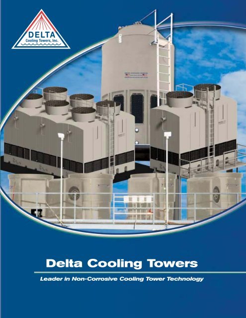
DELTA<br />
<strong>Cooling</strong> <strong>Towers</strong>, <strong>Inc</strong>.<br />
<strong>Delta</strong> <strong>Cooling</strong> <strong>Towers</strong><br />
Leader in Non-Corrosive <strong>Cooling</strong> Tower Technology
Effective 10/2006<br />
INTRODUCTION<br />
History of <strong>Delta</strong> <strong>Cooling</strong> <strong>Towers</strong><br />
General <strong>Cooling</strong> Tower Brochure<br />
Why <strong>Delta</strong> <strong>Cooling</strong> <strong>Towers</strong> are the Industries Best<br />
TECHNICAL DATA<br />
Principles of <strong>Cooling</strong> <strong>Towers</strong> Definitions & Terms<br />
Summer Design Wet Bulb Temperatures<br />
Average Properties of the Materials of Construction<br />
Sizing & Application Data Sheet<br />
PIONEER® FORCED DRAFT COOLING TOWERS<br />
Article: <strong>Cooling</strong> Tower Stands the Test of Time and Elements<br />
Pioneer® Tower Specifications<br />
Engineering Drawings<br />
Pioneer® Optional Accessories<br />
Pioneer® Installation, Operation & Maintenance Manual<br />
PARAGON® INDUCED DRAFT COOLING TOWERS<br />
Paragon® Tower Specifications<br />
Engineering Drawings<br />
Paragon® Optional Accessories<br />
Paragon® Installation, Operation & Maintenance Manual<br />
PREMIER INDUCED DRAFT COOLING TOWERS<br />
Premier Tower Specifications<br />
Engineering Drawings<br />
Premier Optional Accessories<br />
Premier Installation, Operation & Maintenance Manual<br />
TM SERIES INDUCED DRAFT COOLING TOWERS<br />
TM Series Tower Specifications<br />
Engineering Drawings<br />
TM Series Optional Accessories<br />
TM Series Installation, Operation & Maintenance Manual<br />
PACKAGED COOLING SYSTEMS<br />
Packaged <strong>Cooling</strong> Systems Data Sheet<br />
COOLING TOWER ACCESSORIES<br />
Storage Tanks<br />
Prewired Control Panels<br />
Installation Platforms<br />
CONDITIONS OF SALE AND WARRANTY<br />
<strong>Delta</strong> <strong>Cooling</strong> <strong>Towers</strong>, <strong>Inc</strong>.<br />
41 Pine Street ~ PO Box 315<br />
Rockaway, NJ 07866<br />
973-586-2201 / 973-586-2243 fax<br />
The information, recommendations, and opinions set forth herein are offered<br />
solely for your consideration, inquiry and verification and are not, in part or total,<br />
to be construed as constituting a warranty or representation for which we assume<br />
legal responsibility. Nothing contained herein is to be interpreted as authorization<br />
to practice a patented invention without a license.
<strong>Delta</strong> <strong>Cooling</strong> <strong>Towers</strong>, <strong>Inc</strong>. was founded to manufacture and market the initial concept of a<br />
maintenance free seamless one-piece non-corrosive Polyethylene cooling towers, and sold its first<br />
unit in June 1971.<br />
<strong>Delta</strong>'s PIONEER ® forced draft cooling tower line is factory assembled in single modules from 10<br />
through 100 tons of cooling capacity.<br />
<strong>Delta</strong>'s PARAGON ® induced draft cooling towers are factory assembled in single modules, from 100<br />
to 250 tons in single modules.<br />
<strong>Delta</strong>’s PREMIER induced draft cooling towers are offered in 6 single-cell models ranging from<br />
250-500 cooling tons, and features a low profile design. They are designed for ease of<br />
installation to span existing cooling tower structural supports. The Premier towers come<br />
standard pre-mounted on a steel platform.<br />
<strong>Delta</strong>'s TM Series cooling towers are supplied from 250 up to 2000-ton capacity in multi-module<br />
systems, and are CTI certified. They are a double wall polyethylene construction designed in two<br />
sections for shipment purposes. The tower section includes the wet decking, the hot water<br />
distribution system, the mist eliminator and the motor/fan assemblies with the velocity recovery<br />
fan stacks. The other section is the cold-water basin.<br />
In 1981 <strong>Delta</strong> entered the air stripper market and currently markets a standard line of<br />
VANGUARD ® packed column air strippers from 1' through 5' diameter. Larger custom designed<br />
systems can be provided up to 15' diameter.<br />
<strong>Delta</strong> prides itself in its ability to provide the technical expertise necessary to meet the requirements<br />
of any application with respect to stripper design, materials of construction, type of packing and<br />
total system capability. Our capabilities are listed in our general literature, which also shows<br />
installation photographs of some of <strong>Delta</strong>’s air stripper applications.<br />
<strong>Delta</strong> <strong>Cooling</strong> <strong>Towers</strong>, <strong>Inc</strong>.<br />
41 Pine Street ~ PO Box 315<br />
Rockaway, NJ 07866<br />
973-586-2201 / 973-586-2243 fax<br />
The information, recommendations, and opinions set forth herein are offered<br />
solely for your consideration, inquiry and verification and are not, in part or total,<br />
to be construed as constituting a warranty or representation for which we assume<br />
legal responsibility. Nothing contained herein is to be interpreted as authorization<br />
to practice a patented invention without a license.
<strong>Delta</strong> <strong>Cooling</strong> <strong>Towers</strong> are made from a CORROSION PROOF engineered plastic. The<br />
cooling tower shell will never rust, flake, chip, peel or ever need painting or protective<br />
coatings applied. <strong>Delta</strong> believes its towers are the future of the industry. Metal towers do<br />
not have the long-term corrosion protection advantages for outdoor usage. The<br />
galvanizing or other metal treatments only delay the corrosion of the underlying, often<br />
thin gauge sheet metal.<br />
<strong>Delta</strong> manufactures a totally SEAMLESS cooling tower. <strong>Delta</strong> towers are the only large<br />
packaged cooling towers in the industry that have a “one-piece” shell. This means there<br />
are no seams, panels, rivets or other fasteners to fail: compromising the performance or<br />
integrity of the product.<br />
<strong>Delta</strong> stands behind its products with the best warranty in the industry. <strong>Delta</strong> provides a<br />
15-YEAR WARRANTY on the cooling tower’s structural shell. In addition, <strong>Delta</strong>’s<br />
cooling tower motors have a 5-year warranty.<br />
<strong>Delta</strong> <strong>Cooling</strong> <strong>Towers</strong> are LOW MAINTENANCE by design. <strong>Delta</strong> has carefully designed its<br />
products to minimize maintenance issues. Other manufacturers’ towers utilize a more<br />
complicated design to achieve the same performance result. These designs include many<br />
more parts, thereby requiring more maintenance. On <strong>Delta</strong> towers there are no gear<br />
reducers, couplings, additional shafts, or extra bearings to maintain.<br />
<strong>Delta</strong> prides itself on exceptional CUSTOMER SERVICE. Our “can-do” mindset allows us<br />
to meet or exceed any customer’s cooling tower requirements. We offer many product<br />
options and can provide any accessories associated with cooling towers.<br />
<strong>Delta</strong> <strong>Cooling</strong> <strong>Towers</strong>, <strong>Inc</strong>.<br />
41 Pine Street ~ PO Box 315<br />
Rockaway, NJ 07866<br />
973-586-2201 / 973-586-2243 fax<br />
www.deltacooling.com<br />
The information, recommendations, and opinions set forth herein are offered<br />
solely for your consideration, inquiry and verification and are not, in part or total,<br />
to be construed as constituting a warranty or representation for which we assume<br />
legal responsibility. Nothing contained herein is to be interpreted as authorization<br />
to practice a patented invention without a license.
Principle of <strong>Cooling</strong><br />
<strong>Towers</strong><br />
All cooling towers operate<br />
on the principle of<br />
removing heat from water<br />
by evaporating a small<br />
portion of the water that is<br />
re-circulated through the<br />
unit.<br />
The heat that is removed is<br />
called the latent heat of<br />
vaporization.<br />
Each one pound of water<br />
that is evaporated removes<br />
approximately 1,000<br />
BTU’s in the form of latent<br />
heat.<br />
<strong>Delta</strong> <strong>Cooling</strong> <strong>Towers</strong>, <strong>Inc</strong>.<br />
41 Pine Street ~ PO Box 315<br />
Rockaway, NJ 07866<br />
973/586-2201 / 973/586-2243 fax<br />
<strong>Cooling</strong> Tower Terms<br />
and Definitions<br />
APPROACH<br />
The difference between the<br />
temperature of the cold water<br />
leaving the tower and the wetbulb<br />
temperature of the air is<br />
known as the approach.<br />
Establishment of the<br />
approach fixes the operating<br />
temperature of the tower and<br />
is a most important<br />
parameter in determining<br />
both tower size and cost.<br />
BLEED OFF<br />
The circulating water in the<br />
tower which is discharged to<br />
waste to help keep the<br />
dissolved solids concentration<br />
of the water below a<br />
maximum allowable limit. As<br />
a result of evaporation,<br />
dissolved solids concentration<br />
will continually increase<br />
unless reduced by bleed off.<br />
BTU<br />
A BTU is the heat energy<br />
required to raise the<br />
temperature of one pound of<br />
water one degree Fahrenheit<br />
in the range from 32°F to<br />
212°F.<br />
COOLING RANGE<br />
The difference in temperature<br />
between the hot water<br />
entering the tower and the<br />
cold water leaving the tower<br />
is the cooling range.<br />
DRIFT<br />
The water entrained in the air<br />
flow and discharged to the<br />
atmosphere. Drift loss does<br />
not include water lost by<br />
evaporation. Proper tower<br />
design can minimize drift<br />
loss.<br />
HEAT LOAD<br />
The amount of heat to be<br />
removed from the circulating<br />
water within the tower. Heat<br />
load is equal to water<br />
circulation rate (gpm) times<br />
the cooling range times 500<br />
and is expressed in BTU/hr.<br />
Heat load is also an important<br />
parameter in determining<br />
tower size and cost.<br />
MAKEUP<br />
The amount of water required<br />
to replace normal losses<br />
caused by bleed off, drift, and<br />
evaporation<br />
PUMPING HEAD<br />
The pressure required to<br />
pump the water from the<br />
tower basin, through the<br />
entire system and return to<br />
the top of the tower.<br />
TON<br />
An evaporative cooling ton is<br />
15,000 BTU’s/hr.<br />
The information, recommendations, and opinions set forth herein are offered<br />
solely for your consideration, inquiry and verification and are not, in part or total,<br />
to be construed as constituting a warranty or representation for which we assume<br />
legal responsibility. Nothing contained herein is to be interpreted as authorization<br />
to practice a patented invention without a license.
Suggested Summer Design<br />
Wet Bulb Temperatures for<br />
Various U.S Cities<br />
Degree F<br />
State City 1% 5% 15%<br />
Alabama<br />
Birmingham 79 77 76<br />
Mobile 80 79 77<br />
Montgomery 80 78 76<br />
Arizona<br />
Flagstaff 62 59 57<br />
Phoenix 77 75 73<br />
Tucson 73 71 70<br />
Yuma 79 77 75<br />
Arkansas<br />
Little Rock 80 78 77<br />
California<br />
Bakersfield 72 70 67<br />
El Centro 81 79 76<br />
Fresno 73 71 68<br />
Long Beach 72 69 66<br />
Los Angeles 69 67 65<br />
Needles 76 74 72<br />
Oakland 66 63 60<br />
Sacramento 72 69 66<br />
San Diego 71 68 66<br />
San Francisco 65 62 59<br />
Colorado<br />
Denver 65 63 60<br />
Connecticut<br />
Hartford 77 74 72<br />
New Haven 77 75 72<br />
Delaware<br />
Wilmington 79 76 74<br />
D.C.<br />
Washington 78 76 74<br />
Florida<br />
Jacksonville 80 79 77<br />
Miami 80 79 78<br />
Pensacola 82 80 79<br />
Tampa 80 79 77<br />
Georgia<br />
Alma 81 79 77<br />
Atlanta 78 76 74<br />
Augusta 80 78 77<br />
Savannah 81 79 77<br />
Idaho<br />
Boise 68 65 61<br />
Illinois<br />
Chicago 78 75 72<br />
Peoria 78 76 72<br />
<strong>Delta</strong> <strong>Cooling</strong> <strong>Towers</strong>, <strong>Inc</strong>.<br />
41 Pine Street ~ PO Box 315<br />
Rockaway, NJ 07866<br />
.<br />
973/586-2201 / 973/586-2243 fax<br />
The chart shows the average percent of time (June thru September) that the wet bulb<br />
temperature will equal or exceed the degree Fahrenheit value shown.<br />
Degree F<br />
State City 1% 5% 15%<br />
Indiana<br />
Evansville 79 77 75<br />
Fort Wayne 77 75 71<br />
Indianapolis 78 76 73<br />
Iowa<br />
Des Moines 79 76 73<br />
Sioux City 79 76 72<br />
Kansas<br />
Wichita 77 75 73<br />
Kentucky<br />
Louisville 79 77 74<br />
Louisiana<br />
New Orleans 81 79 78<br />
Shreveport 81 79 78<br />
Maine<br />
Augusta 74 71 67<br />
Caribou 72 68 64<br />
Portland 75 71 67<br />
Maryland<br />
Baltimore 79 77 74<br />
Massachusetts<br />
Boston 76 73 70<br />
Worcester 75 71 68<br />
Michigan<br />
Detroit 76 74 70<br />
Flint 77 74 70<br />
Grand Rapids 76 73 70<br />
Pellston 74 71 67<br />
Minnesota<br />
Duluth 73 69 65<br />
Minneapolis 78 74 70<br />
St. Cloud 77 73 69<br />
Missouri<br />
Kansas City 79 76 74<br />
St. Louis 79 77 74<br />
Mississippi<br />
Jackson 80 78 77<br />
Greenwood 81 80 78<br />
Montana<br />
Billings 68 65 62<br />
Helena 65 61 58<br />
Missoula 65 61 58<br />
Nebraska<br />
Lincoln 78 76 72<br />
Omaha 79 76 73<br />
Nevada<br />
Reno 64 61 58<br />
Las Vegas 72 70 66<br />
New Hampshire<br />
Concord 75 72 68<br />
Degree F<br />
State City 1% 5% 15%<br />
New Jersey<br />
Camden 79 77 74<br />
Newark 77 75 72<br />
New Mexico<br />
Albuquerque 66 65 63<br />
Carlsbad 72 71 69<br />
Santa Fe 65 63 61<br />
New York<br />
Albany 76 73 70<br />
Buffalo 75 72 69<br />
New York 77 75 72<br />
Rochester 75 72 69<br />
Syracuse 76 73 70<br />
North Carolina<br />
Asheville 76 74 71<br />
Charlotte 78 76 74<br />
Greensboro 77 76 73<br />
Raleigh 79 77 75<br />
Wilmington 82 80 78<br />
North Dakota<br />
Bismarck 75 71 67<br />
Ohio<br />
Akron 76 74 71<br />
Canton 76 74 71<br />
Cincinnati 79 77 74<br />
Cleveland 76 74 71<br />
Columbus 78 75 72<br />
Dayton 77 74 71<br />
Youngstown 75 73 69<br />
Oklahoma<br />
Oklahoma City 78 76 74<br />
Tulsa 79 77 75<br />
Oregon<br />
Baker 66 63 59<br />
Medford 70 66 63<br />
Portland 69 66 62<br />
Salem 69 66 62<br />
Pennsylvania<br />
Altoona 75 73 70<br />
Erie 76 73 70<br />
Harrisburg 76 74 71<br />
Philadelphia 78 76 73<br />
Pittsburgh 75 73 70<br />
Rhode Island<br />
Providence 76 74 70<br />
Degree F<br />
State City 1% 5% 15%<br />
South Carolina<br />
Charleston 81 79 77<br />
Columbia 79 78 76<br />
Greenville 77 75 73<br />
South Dakota<br />
Sioux Falls 77 74 70<br />
Tennessee<br />
Chattanooga 78 77 75<br />
Knoxville 77 76 74<br />
Memphis 80 79 77<br />
Nashville 79 77 75<br />
Texas<br />
Abilene 76 74 72<br />
Austin 79 77 76<br />
Corpus Christi 81 80 79<br />
Dallas 79 78 76<br />
El Paso 70 68 67<br />
Fort Worth 78 76 75<br />
Galveston 82 81 80<br />
Houston 80 79 78<br />
Lubbock 73 72 70<br />
Port Arthur 81 80 79<br />
San Angelo 74 73 71<br />
San Antonio 77 76 75<br />
Wichita Falls 77 76 74<br />
Utah<br />
Salt Lake City 67 64 62<br />
Vermont<br />
Burlington 75 72 68<br />
Virginia<br />
Norfolk 79 78 76<br />
Richmond 79 77 75<br />
Roanoke 76 74 72<br />
Washington<br />
Seattle 66 63 60<br />
Spokane 66 63 60<br />
Tacoma 66 63 60<br />
Walla Walla 69 66 63<br />
Yakima 69 65 62<br />
West Virginia<br />
Charleston 77 75 73<br />
Elkins 75 72 70<br />
Parkersburg 78 75 73<br />
Wisconsin<br />
Madison 77 74 70<br />
Milwaukee 77 73 70<br />
Wyoming<br />
Cheyenne 63 61 59<br />
The information, recommendations, and opinions set forth herein are offered<br />
solely for your consideration, inquiry and verification and are not, in part or total,<br />
to be construed as constituting a warranty or representation for which we assume<br />
legal responsibility. Nothing contained herein is to be interpreted as authorization<br />
to practice a patented invention without a license.
Country City C<br />
EUROPE<br />
AUSTRIA<br />
Salzburg 21.0<br />
Vienna 21.5<br />
BELGIUM<br />
Brussels 21.0<br />
CYPRUS<br />
Nicosia 24.0<br />
CZECH REPUBLIC<br />
Prague 19.5<br />
DENMARK<br />
Copenhagen 21.0<br />
GERMANY<br />
Berlin 20.0<br />
Bremen 20.0<br />
Cologne 21.0<br />
Frankfurt A.M 21.5<br />
Hamburg 19.0<br />
Hanover 20.0<br />
Kaiserslautern 21.0<br />
Karlsruhe 21.0<br />
Leipzig 21.0<br />
Mannheim 21.5<br />
Munich 21.0<br />
Nuremberg 20.0<br />
Saarbrucken 21.0<br />
Stuttgart 21.0<br />
FINLAND<br />
Helsinki 19.0<br />
FRANCE<br />
Bordeaux 23.5<br />
Lyon 22.0<br />
Marseile 22.5<br />
Paris 21.5<br />
Strasburg 22.0<br />
GREAT BRITIAN<br />
Birmingham 19.5<br />
Glasgow 18.0<br />
London 19.0<br />
GREECE<br />
Athens 22.5<br />
HUNGARY<br />
Budapest 21.0<br />
ICELAND<br />
Reykjavik 14.0<br />
IRELAND<br />
Dublin 19.0<br />
ITALY<br />
Florence 21.5<br />
Genoa 24.5<br />
Milan 23.0<br />
Naples 24.0<br />
Palermo 25.0<br />
Rome 23.0<br />
Turin 24.0<br />
Venice 24.5<br />
NETHERLANDS<br />
Amsterdam 20.0<br />
Den Haag 20.0<br />
Rotterdam 21.0<br />
<strong>Delta</strong> <strong>Cooling</strong> <strong>Towers</strong>, <strong>Inc</strong>.<br />
41 Pine Street ~ PO Box 315<br />
Rockaway, NJ 07866<br />
.<br />
973/586-2201 / 973/586-2243 fax<br />
Country City C<br />
NORWAY<br />
Oslo 19.5<br />
POLAND<br />
Warsaw 21.0<br />
PORTUGAL<br />
Lisbon 22.5<br />
RUMANIA<br />
Bucharest 23.0<br />
RUSSIA<br />
Moscow 20.5<br />
SPAIN<br />
Barcelona 24.0<br />
Madrid 22.5<br />
SWEDEN<br />
Stockholm 19.5<br />
SWITZERLAND<br />
Basel 22.0<br />
Bern 20.5<br />
Geneva 21.0<br />
Lucerne 21.0<br />
Zurich 20.5<br />
YUGOSLAVIA<br />
Belgrade 23.0<br />
AFRICA<br />
ALGERIA<br />
Algiers 22.5<br />
Oran 26.0<br />
ANGOLA<br />
Luanda 27.0<br />
EQYPT<br />
Alexandria 25.5<br />
Cairo 24.5<br />
Luxor 27.0<br />
ETHIOPIA<br />
Addis Ababa 19.0<br />
GHANA<br />
Accra 19.0<br />
KENYA<br />
Nairobi 27.0<br />
LIBERIA<br />
Monrovia 27.0<br />
LIBYA<br />
Tripoli 27.0<br />
MOROCCO<br />
Casablanca 25.0<br />
Tangier 24.0<br />
SENEGAL<br />
Dakar 23.0<br />
SIERRA LEONE<br />
Freetown 27.0<br />
SOUTH AFRICA<br />
Durban 25.0<br />
Johannesburg 21.0<br />
Cape Town 22.0<br />
Pretoria 22.0<br />
SUDAN<br />
Khartoum 27.0<br />
Port Sudan 31.0<br />
SWAZILAND<br />
Windhoek 19.0<br />
TANZANIA<br />
Dar Es Salaam 28.0<br />
Country City C<br />
TUNISIA<br />
Tunis 27.0<br />
ZAIRE<br />
Kinshasa 28.0<br />
Lubumbashi 21.0<br />
NORTH AMERICA<br />
CANADA<br />
Montreal 23.0<br />
Ottawa 23.0<br />
Toronto 24.5<br />
Quebec 23.0<br />
Vancouver 20.0<br />
AUSTRALASIA<br />
AUSTRALIA<br />
Adelaide 20.5<br />
Brisbane 24.5<br />
Melborne 23.0<br />
Sydney 22.5<br />
NEW ZEALAND<br />
Auckland 23.0<br />
ASIA<br />
AFGHANISTAN<br />
Kabul 21.0<br />
CHINA<br />
Canton 28.0<br />
Shanghai 28.0<br />
Hong Kong 28.0<br />
INDIA<br />
Bombay 28.0<br />
Delhi 25.0<br />
Calcutta 28.5<br />
Madras 28.0<br />
INDONESIA<br />
Djakarta 26.5<br />
IRAN<br />
Teheran 22.0<br />
IRAQ<br />
Baghdad 23.5<br />
Basra 28.0<br />
ISRAEL<br />
Haifa 26.5<br />
Jerusalem 21.5<br />
Tel Aviv 26.5<br />
JAPAN<br />
Hiroshima 28.0<br />
Osaka 28.0<br />
Tokyo 26.5<br />
JORDAN<br />
Amman 23.0<br />
KOREA<br />
Seoul 26.0<br />
KUWAIT<br />
Kuwait 29.5<br />
LEBANON<br />
Beirut 26.0<br />
PAKISTAN<br />
Karachi 28.0<br />
PHILIPPINES<br />
Manila 28.0<br />
Country City C<br />
RUSSIA<br />
Vladivostok 22.0<br />
SAUDI ARABIA<br />
Riyadh 26.0<br />
Jeddah 30.5<br />
Dhahran 30.0<br />
SINGAPORE<br />
Singapore 28.0<br />
SRI LANKA<br />
Colombo 28.0<br />
SYRIA<br />
Damascus 23.0<br />
THAILAND<br />
Bangkok 28.0<br />
TURKEY<br />
Ankara 30.5<br />
Istanbul 23.0<br />
VIETNAM<br />
Hanoi 30.0<br />
Saigon 28.5<br />
SOUTH AMERICA<br />
ARGENTINA<br />
Buenos Aires 24.0<br />
BOLIVIA<br />
La Paz 14.0<br />
BRAZIL<br />
Manaos 27.0<br />
Rio de Janeiro 25.5<br />
Sao Paulo 24.0<br />
CHILE<br />
Santiago 21.0<br />
Valparaiso 20.0<br />
COLUMBIA<br />
Bogota 18.0<br />
CUBA<br />
Havana 26.5<br />
GUATEMALA<br />
Guatemala 23.0<br />
MEXICO<br />
Mexico City 16.5<br />
NICARAGUA<br />
Managua 25.5<br />
PANAMA<br />
Panama 26.0<br />
PERU<br />
Lima 24.0<br />
PUERTO RICO<br />
San Juan 26.0<br />
URUGUAY<br />
Montevideo 23.5<br />
VENEZUELA<br />
Caracas 22.5<br />
Maracaibo 28.0<br />
The information, recommendations, and opinions set forth herein are offered<br />
solely for your consideration, inquiry and verification and are not, in part or total,<br />
to be construed as constituting a warranty or representation for which we assume<br />
legal responsibility. Nothing contained herein is to be interpreted as authorization<br />
to practice a patented invention without a license.
<strong>Delta</strong> <strong>Cooling</strong> <strong>Towers</strong>, <strong>Inc</strong>.<br />
41 Pine Street ~ PO Box 315<br />
Rockaway, NJ 07866<br />
973/586-2201 / 973/586-2243 fax<br />
Mechanical Properties:<br />
Polyethylene (Shell Material) Test Method Properties<br />
1. Tensile Strength (@ 20m./min.) ASTM D 638 2600-3000<br />
2. Stiffness Modulus ASTM D 747 56-70 X 103 psi<br />
3. Tensile Impact Strength ASTM D 1822 90-130 ft. lb. /in.2<br />
4. Elongation (@ 20in./min.) ASTM D 638 150-350%<br />
5. Vicat Softening Point ASTM D 1525 230°/238°F<br />
6. Deflection Temperature at 66psi ASTM D 648 172°F<br />
7. Brittleness Temperature ASTM D 746 -94°F<br />
PVC (Wet Decking & Eliminator Material) Test Method Properties<br />
1. Tensile Strength ASTM D 638 7100 psi<br />
2. Flexural Modulus ASTM D 790 300-500 x 103 psi<br />
3. Izod Impact ASTM D 256 0.73 ft. lb/in.<br />
4. Elongation ASTM D 638 150%<br />
5. Deflection Temperature at 66psi ASTM D 648 155°F<br />
6. Brittleness Temperature ASTM D 746 -15°F<br />
PVC (Water Distribution System Material) Test Method Properties<br />
1. Tensile Strength ASTM D 638 7500 psi<br />
2. Flexural Modulus ASTM D 790 560 x 103 psi<br />
3. Izod Impact 140°F ASTM D 256 1.26 ft. lb/in. notch<br />
4. Izod Impact at –40°F ASTM D 256 .035 ft. lb/in. notch<br />
5. Deflection Temperature at 66psi ASTM D 648 169°F<br />
Permanence Tests:<br />
Test Method Polyethylene PVC<br />
1. Outdoor Weathering ASTM D 1435-65T Complete Protection Excellent<br />
2. Accelerated Weathering ASTM E 42 Very Resistant Very Resistant<br />
3. Normal Exposure to Sunlight Complete Protection Complete Protection<br />
4. Accelerated Exposure to Sunlight FADEOMETER Complete Protection Complete Protection<br />
Chemical Properties:<br />
Test Method Polyethylene PVC<br />
1. Weak Acids ASTM D 543 Very Resistant No Effect<br />
2. Strong Acids ASTM D 543 None to Slight None to Slight<br />
3. Weak Alkali ASTM D 543 Very Resistant No Effect<br />
4. Strong Alkali ASTM D 543 Very Resistant No Effect<br />
5. Salts ASTM D 543 Resistant No Effect<br />
6. Sea Salts ASTM D 543 Resistant No Effect<br />
The information, recommendations, and opinions set forth herein are offered<br />
solely for your consideration, inquiry and verification and are not, in part or total,<br />
to be construed as constituting a warranty or representation for which we assume<br />
legal responsibility. Nothing contained herein is to be interpreted as authorization<br />
to practice a patented invention without a license.
DELTA COOLING TOWERS<br />
SIZING & APPLICATION DATA SHEET<br />
COMPANY :____________________________________________________________<br />
ADDRESS:______________________________________________________________<br />
CITY:________________________ STATE:______________ ZIP:_____________<br />
COUNTRY: _____________________________________________________________<br />
CONTACT NAME:______________________________________________________<br />
PHONE:____________________________ FAX:______________________________<br />
EMAIL:__________________________________________________________________<br />
APPLICATION: HVAC / INDUSTRIAL (CIRCLE ONE)<br />
OPERATING CONDITIONS: GALLONS PER MINUTE: ________ GPM<br />
HOT WATER (from process): ________°F COLD WATER (return to process): _______°F<br />
WET BULB TEMPERATURE: ___________°F<br />
RANGE (Difference between hot & cold water) : __________________<br />
APPROACH (Cold water minus Wet Bulb Temp.) :__________________<br />
Please email completed form sales@menaits.com, or fax 0018665448280.<br />
Thank you for considering <strong>MENA</strong> Industrial Technology Supply, <strong>Inc</strong>.<br />
<strong>MENA</strong> Industrial Technology Supply, <strong>Inc</strong>. 2345 CR #38 – Brasher Falls, NY 13613 USA – 0012144021319<br />
www.menaits.com sales@menaits.com
DELTA<br />
<strong>Cooling</strong> <strong>Towers</strong>, <strong>Inc</strong>.<br />
Pioneer ® cooling towers<br />
are forced draft counter flow<br />
design cooling towers with<br />
single module capacities from 10<br />
to 100 cooling tons. These<br />
towers are a unitary seamless<br />
engineered plastic design that<br />
<strong>Delta</strong> has been manufacturing<br />
since 1971 and have been the<br />
standard for long-term trouble-<br />
free operation.<br />
PIONEER ®<br />
Forced Draft, Counter Flow Design<br />
10 - 100 Ton Single Modules<br />
STANDARD FEATURES:<br />
��Seamless Engineered Plastic (HPDE) Shell<br />
��Corrosion Proof Construction<br />
��Forward Curved Centrifugal Blower with Totally Enclosed Motor.<br />
��Factory Assembled for Simple Installation<br />
��15 Year Shell Warranty<br />
��PVC Water Distribution System with Non-clog Large Orifice<br />
Removable Nozzles<br />
��High Efficiency PVC Fill<br />
��Made in the USA<br />
Compare the value <strong>Delta</strong> <strong>Cooling</strong> <strong>Towers</strong> offer against the<br />
value of other comparable units. You will find the benefits<br />
we can provide are unique and superior:<br />
��Cost Reduction - save water costs and sewer taxes. A <strong>Delta</strong><br />
cooling tower pays for itself by recirculating water.<br />
��Non-Corrosive Materials of Construction - impervious to<br />
chemicals, acids, and salts.<br />
��Cost Less to Maintain - will not rust, chip, or ever require<br />
painting for extraordinary tower life.<br />
��Unique Design - provides unlimited flexibility of modular<br />
operation, future upgrade capablity, and location convenience.<br />
��One-Piece Construction - strong and long lasting. Shell is<br />
backed by a 15 year warranty.<br />
��Cost Less to Install - light weight construction reduces rigging<br />
and structural roof support requirements. Maintenance costs<br />
and water treatment chemicals cost are significantly lowered.<br />
OPTIONS AVAILABLE:<br />
��Mounting Platforms<br />
��Two Speed Motors<br />
��Thermostatic On/Off Fan Control Package<br />
��Anti Freeze Basin Heaters<br />
��Pump(s)<br />
��Sump Level Switches<br />
��Stainless Steel Basket Strainers<br />
��Control Panels<br />
��Storage Tanks<br />
Phone: 973-227-0300 • 800-BUY-DELTA • Fax: 973-227-0458 • www.deltacooling.com
DELTA<br />
<strong>Cooling</strong> <strong>Towers</strong>, <strong>Inc</strong>.<br />
CORROSION-<br />
PROOF SHELL<br />
HDPE Plastic<br />
Construction can not<br />
corrode and is<br />
backed by 15 Year<br />
Warranty.<br />
LIGHTWEIGHT<br />
AND HEAVY<br />
DUTY<br />
Plastic is lighter than<br />
conventional cooling<br />
towers and average<br />
wall thickness is 5-10<br />
times sheet metal<br />
towers.<br />
LEAK-PROOF<br />
SUMP<br />
Molded as Unitary<br />
(One-Piece) Structure<br />
that has no joints to<br />
leak or require recaulking<br />
and sealing.<br />
•<br />
•<br />
•<br />
PIONEER ®<br />
Forced Draft, Counter Flow Design<br />
10 - 100 Ton Single Modules<br />
• •<br />
FILL MATERIAL<br />
DRIFT<br />
ELIMINATOR<br />
PVC drift eliminator<br />
prevents water droplets<br />
from leaving the tower.<br />
NOZZLE WATER<br />
DISTRIBUTION<br />
SYSTEM<br />
Non-Clog large orifice<br />
removable nozzles evenly<br />
distribute the water.<br />
AIR MOVING<br />
SYSTEM<br />
Totally enclosed<br />
cooling tower motor<br />
powers centrifugal<br />
blower with optional<br />
HDPE weather hood.<br />
Model Approximate Weight Dimensions Capacity Fan Motor Sump Capacity<br />
Number Shipping Operating Dia. x Ht. Tons HP Gallons<br />
Δt-10 350 705 38" x 78" 10 1 40<br />
Δt-15 360 725 38" x 78" 15 1.5 40<br />
Δt-20 385 750 38" x 78" 20 2 40<br />
Δt-25 405 765 38" x 78" 25 3 40<br />
Δt-30 710 1500 56" x 76" 30 5 75<br />
Δt-40 730 1525 56" x 76" 40 5 75<br />
Δt-50 910 2610 80" x 80" 50 5 157<br />
Δt-75 970 2675 80" x 80" 75 7.5 157<br />
Δt-100 1030 2730 80" x 80" 100 10 157<br />
The information, recommendations and opinions set forth herein are offered solely for your consideration, inquiry and verification, and are not,<br />
in part or total, to be construed as constituting a warranty or representation for which we assume legal responsibility.<br />
<strong>Delta</strong> <strong>Cooling</strong> <strong>Towers</strong><br />
Leader in Non-Corrosive <strong>Cooling</strong> Tower Technology<br />
Tel: 973-227-0300 • Fax: 973-227-0458 • 800-BUY-DELTA • www.deltacooling.com<br />
•<br />
High efficiency spiral wound<br />
PVC for maximum cooling.<br />
•
<strong>Delta</strong> <strong>Cooling</strong> <strong>Towers</strong>, <strong>Inc</strong>.<br />
41 Pine Street<br />
P.O. Box 315<br />
Rockaway, New Jersey 07866-0315<br />
Telephone 973.586.2201<br />
Fax 973.586.2243<br />
www.deltacooling.com<br />
sales@deltacooling.com<br />
Pioneer ® Forced Draft <strong>Cooling</strong> Tower Specifications<br />
Pioneer ® cooling towers are a forced draft counter-flow cooling tower with single module<br />
capacities from 10 to 100 cooling tons. These towers are a unique design that <strong>Delta</strong><br />
<strong>Cooling</strong> <strong>Towers</strong> has been manufacturing since 1971 and have been very well received<br />
in both commercial and industrial applications. There are two overriding principles that<br />
make Pioneer ® cooling towers an excellent selection.<br />
The towers are corrosion-proof, not corrosion-protected, which is an important<br />
distinction of <strong>Delta</strong> towers. <strong>Cooling</strong> towers are outdoor equipment, either on roofs or<br />
sides of buildings, and are subjected to weather extremes continuously. <strong>Delta</strong> towers<br />
are manufactured in a seamless engineered plastic (HDPE) structural shell which is<br />
corrosion-proof and will not rust, chip, peel, crack or ever need painting or additional<br />
protective coatings. Comparably priced towers are often sheet metal with a galvanized<br />
coating. Zinc galvanizing provides only an interim protection against corrosion. This<br />
galvanizing wears away, often unevenly, exposing sheet metal to the rapid corrosive<br />
environment of cooling tower duty. The first engineered plastic cooling towers <strong>Delta</strong><br />
shipped in 1971 show no signs of degradation in the structural shell today!<br />
The second principle of <strong>Delta</strong> towers is the engineering that led to a simplicity of design,<br />
translating into reliability and a trouble-free life of the towers. From the seamless<br />
cooling tower shell to the easy to maintain blower assembly, there are less overall<br />
components and systems within the tower to maintain. The towers are shipped factory<br />
complete with little more installation steps than hooking up the electrical and water.<br />
This design simplicity is recognized in many other industries as a key goal and leads to<br />
greater reliability and owner peace of mind.<br />
The Pioneer ® design has a tremendous track record for long-term durability and<br />
continues to be the choice for cooling tower application up to 100 cooling tons.
<strong>Delta</strong> <strong>Cooling</strong> <strong>Towers</strong>, <strong>Inc</strong>, Pioneer ! Forced Draft <strong>Cooling</strong> Tower Specifications, Page 2 of 5<br />
PART 1 GENERAL<br />
1.1 SCOPE<br />
PIONEER ! FORCED DRAFT COOLING TOWER<br />
Work included to furnish and install <strong>Delta</strong> <strong>Cooling</strong> Tower Model !t_____ cooling<br />
tower(s) consisting of all equipment necessary to provide a complete operating<br />
system to remove specified heat load. <strong>Cooling</strong> towers shall be packaged, factory<br />
pre-assembled to the fullest extent possible, forced draft, counter flow design<br />
1.2 RELATED WORK<br />
{insert related work document here}<br />
1.3 REFERENCES - STANDARDS<br />
AMCA - Air Moving and Conditioning Association<br />
ASTM - American Society for Testing and Materials<br />
ANSI - American National Standards Institute<br />
ASME - American Society of Mechanical Engineers<br />
1.4 QUALIFICATIONS<br />
The cooling tower shall be manufactured by a company with at least 30 years<br />
experience manufacturer of seamless engineered polyethylene cooling tower<br />
systems.<br />
1.5 WARRANTY<br />
Shell shall be warranted for 15 years and all other equipment shall be warranted<br />
for one year against material and workmanship defects from date of shipment.<br />
1.6 SUBMITTALS<br />
Shop drawings shall be provided and shall include but not be limited to:<br />
A. System dimension<br />
B. Operating and dry weight<br />
C. Details of equipment<br />
D. Mounting and support requirements<br />
E. Descriptions and specifications<br />
PART 2 PRODUCT<br />
The cooling tower specified shall be factory assembled to the fullest extent<br />
possible.
<strong>Delta</strong> <strong>Cooling</strong> <strong>Towers</strong>, <strong>Inc</strong>, Pioneer ! Forced Draft <strong>Cooling</strong> Tower Specifications, Page 3 of 5<br />
2.1 Forced Draft <strong>Cooling</strong> Tower, _____ tons capacity, _____GPM, ____ " F hot<br />
water temperature, ____"F cold water temperature, ____"F wet bulb<br />
temperature<br />
A. <strong>Cooling</strong> tower<br />
1. Shell shall be seamless, non-corrosive, hi-impact high density<br />
polyethylene (HDPE) of leak proof design. Shell wall shall exceed 1/4"<br />
average thickness. Structural shell shall be warranted for 15 years by<br />
the manufacturer. The structural shell shall be capable of withstanding<br />
water temperatures up to 160"F on a continual basis.<br />
2. Sump shall be integral with cooling tower shell, creating a one-piece<br />
seamless structure.<br />
3. Inspection port with removable HDPE cover located above the integral<br />
cold sump for accessibility to automatic make-up valve and adjustable<br />
float.<br />
4. Fittings shall be non-corrosive polyvinyl chloride (PVC) bulkhead fittings<br />
with neoprene gaskets for inlet, outlet, drain, overflow and make-up (FPT)<br />
connections.<br />
5. All outlet fittings for pump suction applications shall be provided with a<br />
vortex breaker.<br />
6. Make up assembly, when incorporated in the sump of the cooling tower,<br />
shall be a mechanical valve assembly, adjustable height for varying<br />
operating conditions.<br />
The engineered plastic shell is the optimum material for cooling tower construction. The material<br />
is molded into a totally seamless shell which will never leak, unlike conventional cooling towers<br />
which require many panels, joints, seams, seam gaskets, caulking and hundreds of bolts or other<br />
fasteners to maintain the integrity of the product. The <strong>Delta</strong> structural shell will never rust, chip,<br />
crack or ever need painting or further protective coatings. The structural shell is warranted for<br />
15 years which is much longer than other available cooling towers.<br />
Galvanized steel towers provide only interim corrosion protection. The zinc galvanizing is<br />
designed only to delay corrosion as the zinc wears steadily away. Moderately high temperatures<br />
and various water chemical treatments speed up this leaching of zinc into the water or<br />
atmosphere. With only ounces per square foot of corrosion protection, it is only a matter of<br />
time till corrosion of the underlying sheet steel sets in.<br />
Thin fiberglass panels can also not match the structural integrity of <strong>Delta</strong>s' seamless engineered<br />
plastic. Over time, if that long, leaks can develop at the joints even with gaskets and caulking<br />
applied. Thin fiberglass when exposed to the wide range of outdoor weather elements is also<br />
subject to delaminating, wicking and overall degradation
<strong>Delta</strong> <strong>Cooling</strong> <strong>Towers</strong>, <strong>Inc</strong>, Pioneer ! Forced Draft <strong>Cooling</strong> Tower Specifications, Page 4 of 5<br />
B. Water distribution<br />
Totally enclosed, non-corrosive, polyvinyl chloride (PVC) spray tree with<br />
non-clog full cone spray nozzle distribution system. Threaded nozzle(s)<br />
shall be interchangeable and shall be capable of being substituted with a<br />
larger diameter orifice for increased flow conditions without increasing inlet<br />
pressure.<br />
C. Wet decking<br />
Spirally wound and bonded, one-piece, non-corrosive, polyvinyl chloride<br />
(PVC) wet decking. Non-corrosive, (PVC) hand straps secured to wet<br />
decking and drift eliminator sections for easy removal.<br />
D. Drift eliminator<br />
Drift eliminator shall be spirally wound and bonded, one-piece, non-corrosive,<br />
polyvinyl chloride (PVC) with non-corrosive PVC straps for easy removal for<br />
internal inspection and maintenance.<br />
E. Fan assembly<br />
1. Forward curved centrifugal belt driven blower assembly, statically and<br />
dynamically balanced wheel, constructed of heavy duty, corrosionresistant<br />
steel with dipped and baked alkyd finish.<br />
2. Motor shall be Totally Enclosed Fan Cooled suitable for 208 or 230/460<br />
volt, 3 phase, 60 cycle operation.<br />
3. Motor shall be warranted against defects in materials and workmanship<br />
for 5 years.<br />
F. Blower Hood<br />
1. Blower hood shall completely enclose the blower, motor and rotating<br />
machinery to offer maximum protection to personnel.<br />
2. Blower hood shall provide protection against rain and windblown debris<br />
entering blower inlet, also protect the motors and drives.<br />
3. Blower hood shall be molded from high density polyethylene (HDPE)<br />
consistent with the tower shell.<br />
4. Blower hood shall dampen sound of blower assembly by 3 dBA at 5 feet.
<strong>Delta</strong> <strong>Cooling</strong> <strong>Towers</strong>, <strong>Inc</strong>, Pioneer ! Forced Draft <strong>Cooling</strong> Tower Specifications, Page 5 of 5<br />
5. Hood inlets shall be covered with a PVC coated 3/8" #2 wire mesh screen<br />
fastened to the hood with stainless steel hardware.<br />
G. Hardware<br />
PART 3 EXECUTION<br />
All hardware shall be 304 Stainless Steel<br />
1. GENERAL - INSTALLATION<br />
Installation of equipment shall conform to or be in compliance with the<br />
manufacturers recommendations.<br />
2. TESTING<br />
A. Contractor shall perform all field testing and final adjustment of cooling tower<br />
equipment in accordance with provision of manufacturer<br />
B. Contractor shall certify that all operation criteria is within normal operating<br />
range as specified by the manufacturer.<br />
C. Should any part of the cooling tower equipment fail to meet any specified<br />
requirement, adjust, repair or replace any and all defects or inoperative parts<br />
immediately with manufacturers recommended parts or procedures.
AIRFLOW SWITCH<br />
The airflow switch is desirable when loss of airflow will have an adverse affect on system operation.<br />
This switch will indicate loss of airflow from many causes including, but not limited to: belt slippage, belt<br />
failure, motor failure, thermal overload shutdown, media failure, etc.<br />
The airflow switch is an on/off device that can be operated in two modes:<br />
A) Will indicate total loss of airflow as installed at the factory, or<br />
B) Can indicate loss of a limited amount of airflow by varying the insertion depth of the sensing<br />
elements.<br />
The enclosure is rated NEMA 7 and 9 as standard. The contacts have a rating of 5 amperes at 125/250<br />
VAC and are SPDT. It can be utilized for system shutdown, warning lights, or other functions.<br />
ANTIFREEZE PACKAGE / RESISTANCE HEATING OPTION<br />
The antifreeze package is supplied to provide protection against freezing of standing water in the cooling<br />
tower sump due to shutdown during winter operation. The option is provided when draining the system<br />
during periods of prolonged shutdown is not feasible, such as during weekends, or when a separate<br />
gravity feed indoor storage tank is not part of the re-circulation system. Resistance heating of the sump<br />
water provides protection, and this package includes the following components:<br />
Immersion Heater:<br />
Capacity sized for service ~ NEMA 4 enclosure<br />
t-10 thru t-25 2000 watt – 2” thread<br />
t-10 thru t-40 4500 watt – 2.5” thread<br />
t-50 thru t-150 6000 watt – 2.5” thread<br />
Thermostat Assembly:<br />
Thermostat is to be set in field. Recommended setting is approximately 38°F.<br />
NEMA 4 enclosure with SPDT switch ~ 30-130°F temperature range ~ 120/277 Volt<br />
with ¾” SCH 80 bulkhead fitting and a ¾” x ½” SCH 40 reducer<br />
Liquid Level Switch Assembly:<br />
NEMA 7 and 9 enclosures are standard on this SPDT level switch. This insures that the<br />
heating element is submerged prior to energizing to prevent immersion heater burn cause<br />
of low water level.<br />
Heater Contactor:<br />
NEMA 1 enclosure is standard. Open style for control panel mounting is available. This<br />
contactor is mounted in the control panel when the panel is purchased from <strong>Delta</strong>.<br />
PVC bulkhead fittings, for local installation, are included in component prices. Protection of external<br />
piping by heat tracing and insulation is recommended but not included.<br />
ANTIFREEZE PACKAGE / SOLENOID DRAIN VALVE<br />
This option is utilized when freezing of standing water in the cooling tower sump could occur due to system<br />
shutdown during winter operation. An electrically actuated valve will open when the pumps are not operating<br />
and the temperatures approach freezing. The valve can be installed in the sump drain fitting of the tower (at<br />
the factory) or remotely at the piping low point (by others in the field).<br />
Components provided are:<br />
A) Electrically actuated to close, spring to open, 2-way valve, 1” line size, with NEMA 4 enclosure.<br />
B) 1” PVC tee<br />
C) 1” PVC plug<br />
D) Temperature switch with bulkhead fitting<br />
<strong>Delta</strong> <strong>Cooling</strong> <strong>Towers</strong>, <strong>Inc</strong>.<br />
41 Pine Street ~ PO Box 315<br />
Rockaway, NJ 07866<br />
973/586-2201 / 973/586-2243 fax
When power is removed the valve automatically reverts to the open position. This feature ensures freeze<br />
protection even during a power outage.<br />
BLOWER CORROSION PROTECTION<br />
Premium blower corrosion protection is desirable when the unit will be operated in highly corrosive<br />
atmospheres such as paper mills, coastal areas, chemical plants, etc. The premium blower corrosion<br />
protection option consists of complete PVC encapsulation of the blower wheel and housing and frame. A T-<br />
304 stainless steel shaft is also included. This option offers an extremely cost effective alternative to FRP<br />
blower assemblies. The blowers and frames are prepared at the factory with all holes and cutouts completed.<br />
The entire assembly is sandblasted and then dipped in a molten PVC solution that coats the entire surface.<br />
When dry, the PVC attains an average thickness of 30 mils and forms a complete covering of the standard<br />
frame and rousing. The blower wheel is coated in the same manner, except for the shaft bore, and is then<br />
rebalanced both statically and dynamically. After final assembly, the shaft and sheaves are coated with a<br />
specially formulated shaft coating material that conforms to MIL-C-16173D, GR 1 & 4. The result is a<br />
blower assembly that will give years of corrosion free service even under the most adverse conditions.<br />
BLOWER GUARD<br />
The blower guard offers protection from accidentally contacting the rotating components of the fan such as<br />
the wheel, shafts and the v-belts. The blower guard is also utilized as a screen for outdoor installations to<br />
prevent leaves and other debris from entering the tower through the double-sided blower inlets.<br />
The guard is fabricated of PVC coated 3/8” #2 wire mesh screen attached to the blower frame with stainless<br />
steel fasteners.<br />
BLOWER HOOD<br />
The blower hood completely enclosed the blower to offer maximum protection to personnel who might<br />
accidentally contact the rotating components. The blower hood provides protecting against rain and<br />
windblown debris entering the standard double inlet blower assemblies. It also protects the motors and drives<br />
from water spray which may affect their operation. Furthermore, the hood offers an aesthetic quality to the<br />
blower assembly because it is molded from the same medium density polyethylene material as the tower shell<br />
and its appearance is, therefore, consistent with the tower shell. The hood also serves as an additional sound<br />
dampening device for the already quiet standard <strong>Delta</strong> blower assemblies. With these hoods properly<br />
installed, a 3-dBA reduction at 5 feet is common. The hood inlets are covered with PVC coated 3/8” #2 wire<br />
mesh screen fastened to the hood with stainless steel hardware.<br />
BLOWER THERMOSTATS – Single Stage and Two-Stage<br />
The fan thermostat is used to minimize operating costs. The thermostat senses water temperature and<br />
controls the blower operation during cold weather service. When cold-water temperature drops below<br />
design, the blower will shut off saving motor hp operating costs and serves as an antifreeze device.<br />
As the cold-water temperature rises and approaches the design temperature, the thermostat signals the<br />
blower to start in order to maintain the cold water design temperature.<br />
A single stage thermostat controls the blower on and off and is provided with a standard single<br />
speed motor.<br />
A two-stage thermostat is required for two speed motor operation and controls the blower from<br />
‘on’ to ‘half speed’ and then to ‘off’. At half speed operation the motor operates at only ¼ full<br />
load BHP. Two stage thermostats must be wired to <strong>Delta</strong> specifications.<br />
The thermostat has a 5°F differential in its operating range of 30°F to 130°F. The contacts are SPDT and<br />
<strong>Delta</strong> <strong>Cooling</strong> <strong>Towers</strong>, <strong>Inc</strong>.<br />
41 Pine Street ~ PO Box 315<br />
Rockaway, NJ 07866<br />
973/586-2201 / 973/586-2243 fax
have a 15 Amp UL rating. They are complete with NEMA 4 enclosures suitable for outdoor mounting.<br />
The thermostat can be provided loose, or installed in the cooling tower sump, or an indoor storage tank.<br />
When the thermostat is supplied with a cooling tower or storage tank provided by <strong>Delta</strong>, the package<br />
includes installation with a ¾” Schedule 80 PVC bulkhead fitting and a ¾” x ½” Schedule 40 PVC<br />
reducer bushing. Thermostat operating range must be set in the field. Recommended setting is<br />
approximately 70°F to 72°F, but will vary depending on the application and the installation location.<br />
BOTTOM OUTLET<br />
A bottom outlet provides for complete drainage of water from the cooling tower sump. This option is<br />
attractive when indoor tanks are utilized for complete drainage of the cooling tower. This prevents<br />
standing water from possibly freezing and damaging PVC piping.<br />
CONTROL PANEL<br />
A control panel is required any time there are electrical devices involved in a system. The standard<br />
features of a <strong>Delta</strong> supplied control panel are:<br />
A) NEMA 3R water tight enclosure<br />
B) Single speed motor starter<br />
C) 110V transformer with fuses<br />
D) Blower operating lights<br />
E) Blower selector switches<br />
F) Terminal strips<br />
G) 208V or 230V or 460V or 575V / 3Ph / 60Hz<br />
Optional items available:<br />
!" Disconnect switch: either fused, unfused or magnetic circuit breaker type.<br />
!" Motor starter fuses or circuit breakers.<br />
!" Additional motor starters, selector switches and lights to interface with existing systems,<br />
remote pumps, etc.<br />
!" Any other NEMA enclosure manufactured.<br />
!" Pre-mounting of control panel and pre-wiring of skid mounted options with Liquid-Tite<br />
conduit or EMT. (Consult factory for add pricing)<br />
<strong>Delta</strong> also can provide programmable controllers, computer interfacing, telemetry, and any other type of<br />
control system required. Pre-mounting and pre-wiring of the control panel for a system installation are<br />
available. This minimizes the labor required for field installation.<br />
EQUALIZER FITTINGS<br />
This option is desirable for multiple module installations to provide equal liquid levels in the sumps of the<br />
individual modules and allows for the installation of only one (1) water make-up line. <strong>Delta</strong> provides the<br />
bulkhead fittings installed in the cooling towers to provide for gravity flow from one tower sump to<br />
another. The equalizer connection is not for full flow transfer (ex: pumping from one unit to another).<br />
The connecting piping should be field installed and is the responsibility of others.<br />
FLANGED ADAPTORS<br />
Standard PVC bulkhead fittings are (FPT) female threaded connections. This option provides 125lb<br />
Schedule 80 PVC flanged connection at approximately 6” projection minimum from the cooling tower.<br />
Gaskets and hardware are not provided by <strong>Delta</strong> and should be provided by others with the piping<br />
companion flange.<br />
<strong>Delta</strong> <strong>Cooling</strong> <strong>Towers</strong>, <strong>Inc</strong>.<br />
41 Pine Street ~ PO Box 315<br />
Rockaway, NJ 07866<br />
973/586-2201 / 973/586-2243 fax
HIGH SUMP LEVEL SWITCH<br />
The hump sump level switch option is utilized when a potential overflow must be avoided. Switch<br />
elevation is set below the point when the water in the sump will overflow onto the ground. The switch<br />
can be used to illuminate a light, shut off the influent feed pump or initiate some other device or alarm.<br />
This package consists of a NEMA 7 and 9 liquid level switch mounted in a PVC bulkhead fitting<br />
assembly with a 2” x 1” reducer bushing.<br />
MASTIC COATING OF BLOWER ASSEMBLY<br />
Mastic coating of the blower wheel, housing and frame is desirable when additional corrosion protection<br />
is required. The mastic coating is applied directly over the standard enamel finish. This option is<br />
recommended in areas of continuous high humidity. It also provides protection from corrosive<br />
compounds, acids, etc. The material used is a brush on, solvent based, asphaltic film coating which is<br />
impervious to standing water and airborne spray. Mastic coating has proven successful in prolonging the<br />
average life of a standard blower assembly. After final assembly, the blower shaft and sheaves are coated<br />
with a special coating material. This coating conforms to MIL-C-16173D, GR 1 & 4. For best results,<br />
periodic recoating of both the wheel and housing are recommended.<br />
OUTLET STRAINER BASKET<br />
This option is desirable to prevent debris that may have entered the cooling tower sump from getting into<br />
the pump, or the rest of the cooling water system. This option is recommended to minimize particle size<br />
that could foul chillers, heat exchangers, compressors or the cooling tower nozzles. A vortex breaker<br />
pipe, which is provided as standard on pump suction applications, is included to maximize the inlet area<br />
and prevent cavitation. The strainer is made from a vortex breaker pipe surrounded by 3/16” #2 PVC<br />
coated mesh screen. Finer mesh screens can be overlaid to minimize particle size. Consult <strong>Delta</strong> for add<br />
prices and availability.<br />
PLATFORM<br />
The platform is a desirable option when a flat smooth uniform surface is not available for mounting<br />
<strong>Delta</strong>’s cooling towers. The platform must be mounted and supported in accordance with <strong>Delta</strong>’s<br />
recommendations. This option includes a steel-mounting platform finished in black semi-gloss alkyd<br />
paint.<br />
PUMP<br />
The pump package is offered to allow for single source responsibility of cooling tower equipment. The<br />
size of the pump is determined by two factors:<br />
A) Flow rate<br />
B) Total dynamic head<br />
The customer is responsible for supplying this information. The pumps come complete closed-coupled<br />
with mechanical seals and ODP, 208/230/460V, 3 phase motor. TEFC motors are available.<br />
PUMP MOUNTING<br />
This option is available when the skid mounting option is also selected. A pump is mounted onto the<br />
platform and the suction is pre-piped with PVC Schedule 80 pipe and fittings. This reduces the amount of<br />
field labor involved in installing a cooling tower system.<br />
<strong>Delta</strong> <strong>Cooling</strong> <strong>Towers</strong>, <strong>Inc</strong>.<br />
41 Pine Street ~ PO Box 315<br />
Rockaway, NJ 07866<br />
973/586-2201 / 973/586-2243 fax
SKID MOUNTING ASSEMBLY<br />
The skid mounting assembly is a desirable option that minimized the field labor required to install a Pioneer®<br />
cooling tower. <strong>Inc</strong>luded with this option is a steel-mounting platform finished in black semi-gloss alkyd<br />
paint, with the cooling tower and blower assembled and mounted to the platform. Guy Wires are included<br />
and assembled to stabilize the tower onto the platform. Additional options can readily be mounted onto the<br />
platform to complete the factory assembly. These options include: blower hood, influent and/or effluent<br />
pumps, pre-piping of the pumps, mounting of a control panel, and pre-wiring of the control panel.<br />
STORAGE TANK<br />
The tank is utilized when extra water capacity is required. Potential applications are for system modulation<br />
when pumping flow rates vary, or for water storage. A hot/cold tank arrangement may be required in those<br />
cases where the process hot water exceeds the maximum allowable inlet water temperature. The cooling<br />
tower would flow more water than the process and the difference would be mixed with the hot water to reduce<br />
its temperature. The tank and optional cover are fabricated of medium density polyethylene. All fittings are<br />
Type 1 PVC.<br />
TWO-SPEED BLOWER MOTOR<br />
Two speed blower motors provide cold-water temperature control by means of airflow modulation, allowing<br />
for design cold-water temperature at minimum operating cost. This is especially desirable for multiple<br />
module applications. When provided with a two-stage thermostat, the motor can be reduced to half speed<br />
when cold water sump temperature approaches design. The motor will shut off when the cold-water<br />
temperature falls below design. Two-speed TEFC motors are provided for single voltage 3-phase operation<br />
only. Single-phase dual voltage motors are not available.<br />
NOTE: a ½ reduction in motor speed corresponds to ½ reduction airflow. At half speed operation,<br />
only 1/8 BHP is consumed.<br />
VIBRATION CUTOUT SWITCH<br />
The vibration cutout switch option is utilized when excessive vibration of the rotating machinery is<br />
undesirable. Excessive vibration can be caused by worn or failed bearings, misalignment and/or wheel<br />
unbalance. This device helps prevent further potential damage by shutting the motor off. It is wired in series<br />
with the motor starter coil and has dry contact rating of 10-ampere capacity at 120 VAC. <strong>Delta</strong> provides the<br />
vibration cutout switch installed on the blower when ordered as a component of a new cooling tower or on a<br />
replacement blower assembly.<br />
<strong>Delta</strong> <strong>Cooling</strong> <strong>Towers</strong>, <strong>Inc</strong>.<br />
41 Pine Street ~ PO Box 315<br />
Rockaway, NJ 07866<br />
973/586-2201 / 973/586-2243 fax
<strong>Delta</strong> <strong>Cooling</strong> <strong>Towers</strong>, <strong>Inc</strong>.<br />
Pioneer ! Forced Draft <strong>Cooling</strong><br />
<strong>Towers</strong><br />
Installation, Operation and Maintenance<br />
Manual<br />
"
Table of Contents<br />
<strong>Delta</strong> <strong>Cooling</strong> <strong>Towers</strong> Principle of <strong>Cooling</strong> <strong>Towers</strong>………………..………………1<br />
<strong>Cooling</strong> Tower Terms & Definitions…………………….1<br />
Installation Safety Procedures…..………………………………….……. 2<br />
Location of the <strong>Cooling</strong> Tower……..…………………… 2<br />
Hoisting………………………….……..………...…………….. 2<br />
<strong>Cooling</strong> Tower Installation………………………………….2<br />
Cold Weather Protection…………………………………….3<br />
Piping and Tower Connections………………………….. 4<br />
Duct to Blower Housing Installation……………………. 4<br />
PVC Solvent Cementing Instructions…………………… 5<br />
Operation V-Belt Alignment and Tensioning…..………..…….…… 5<br />
Initial Start-up……..……………..…………………………….5<br />
Operating Design Condition Checklist……………….….6<br />
Maintenance Water Treatment……………..…..………..…….….……… 6<br />
Disassembly and Cleaning……..………………………….. 7<br />
Preventative Maintenance Checklist….……………..…. 8<br />
Recommended Replacement Parts….………………..…8<br />
Important: <strong>Delta</strong>’s cooling towers have been designed to provide trouble-free service over an extended period of time. To obtain<br />
the design performance, it is necessary that the cooling tower be installed, operated and maintained as prescribed in<br />
these instructions.<br />
Only persons possessing the skill and experience described herein should attempt to install this equipment. Prior to<br />
installation, these instructions should be read carefully by the person who is to install the cooling tower to be certain<br />
that its installation, operation and maintenance are thoroughly understood.<br />
Questions regarding the installation, operation or maintenance of this equipment should be directed to <strong>Delta</strong> <strong>Cooling</strong><br />
<strong>Towers</strong>, <strong>Inc</strong>., Rockaway, New Jersey, (Telephone: 973/586-2201).<br />
Step-by-step instructions contained in this brochure are based on normal installation conditions only. Abnormal or<br />
unusual combinations of field conditions should be brought to the attention of <strong>Delta</strong> <strong>Cooling</strong> <strong>Towers</strong> or its<br />
representative prior to installation of the equipment. The information contained herein is subject to change without<br />
notice in the interest of product improvement.<br />
Rev. 02-17-04
<strong>Delta</strong> <strong>Cooling</strong> <strong>Towers</strong>, <strong>Inc</strong>.<br />
Principle of <strong>Cooling</strong> <strong>Towers</strong><br />
All <strong>Cooling</strong> <strong>Towers</strong> operate on the principle<br />
of removing heat from water by evaporating<br />
a small portion of the water that is<br />
recirculated through the unit.<br />
The heat that is removed is called the<br />
latent heat of vaporization.<br />
Each one pound of water that is<br />
evaporated removes approximately 1,000<br />
BTU's in the form of latent heat.<br />
<strong>Cooling</strong> Tower Terms and<br />
Definitions<br />
BTU - A BTU is the heat energy required to<br />
raise the temperature of one pound of water<br />
one degree Fahrenheit in the range from<br />
32° F. to 212° F.<br />
<strong>Cooling</strong> Range - The difference in<br />
temperature between the hot water entering<br />
the tower and the cold water leaving the<br />
tower is the cooling range.<br />
Approach - The difference between the<br />
temperature of the cold water leaving the<br />
tower and the wet-bulb temperature of the<br />
air is known as the approach. The approach<br />
fixes the operating temperature of the tower<br />
and is a most important parameter in<br />
determining both tower size and cost.<br />
Drift - The water entrained in the air flow<br />
and discharged to the atmosphere. Drift loss<br />
does not include water lost by evaporation.<br />
Proper tower design and operation can<br />
minimize drift loss.<br />
Heat Load - The amount of heat to be<br />
removed from the circulating water through<br />
the tower. Heat load is equal to water<br />
circulation rate (gpm) times the cooling<br />
range times 500 and is expressed in BTU/hr.<br />
Heat load is also an important parameter in<br />
determining tower size and cost.<br />
1<br />
Ton - An evaporative cooling ton is 15,000<br />
BTU's per hour.<br />
Wet-Bulb Temperature - The lowest<br />
temperature that water theoretically can<br />
reach by evaporation. Wet-Bulb<br />
Temperature is an extremely important<br />
parameter in tower<br />
selection and design and should be<br />
measured by a psychrometer.<br />
Pumping Head - The pressure required to<br />
pump the water from the tower basin,<br />
through the entire system and return to the<br />
top of the tower.<br />
Make-Up - The amount of water required<br />
to replace normal losses caused by bleedoff,<br />
drift, and evaporation.<br />
Bleed Off (Blowdown) - The circulating<br />
water in the tower which is discharged to<br />
waste to help keep the dissolved solids<br />
concentrating in the water below a<br />
maximum allowable limit. As a result of<br />
evaporation, dissolved solids concentration<br />
will continually increase unless reduced by<br />
bleed off.
Installation of Your Pioneer® <strong>Cooling</strong> Tower<br />
Safety Procedures<br />
CAUTION:<br />
Observe safety procedures during<br />
installation and whenever construction is<br />
under way.<br />
!" Always disconnect & lock out main<br />
power supply before working on motors and<br />
other electrical equipment.<br />
!" Stand clear of rotating equipment<br />
during start-up.<br />
!" Before start-up replace all guards<br />
removed during installation, that protect<br />
pinch areas of V-belts, sheaves and other<br />
rotating equipment.<br />
!" Avoid contact with open flame or heat<br />
source that could cause combustion.<br />
Observe recommended safety precautions<br />
whenever construction involving welding, a<br />
cutting torch, a blowtorch or any other such<br />
equipment is under way within the<br />
immediate area.<br />
How to Prevent Reverse<br />
Siphoning:<br />
Reverse siphoning is a back flow of nonpotable,<br />
recirculating water into a potable<br />
water system which can occur through the<br />
make-up float valve assembly located in the<br />
water reservoir of a cooling tower.<br />
Should the valve malfunction, blockage<br />
of the overflow or outlet lines would cause a<br />
high water level in the reservoir, causing<br />
the make-up water pressure to drop below<br />
atmospheric pressure creating a vacuum at<br />
the make-up inlet.<br />
To prevent reverse siphoning, install a<br />
check valve in the water make-up supply<br />
line to the cooling tower.<br />
NOTE: Do not cap the overflow connection.<br />
Location of the Pioneer ®<br />
<strong>Cooling</strong> Tower<br />
Proper location of the cooling tower is<br />
essential to its satisfactory operation. The<br />
following are recommendations for<br />
selecting a cooling tower location. Consult<br />
the factory or our representatives for<br />
additional assistance in selecting equipment<br />
and equipment locations.<br />
!" Select an open site having an<br />
unobstructed air supply and free air<br />
motion.<br />
!" If the site is adjacent to a wall or other<br />
structure that blocks prevailing winds, install<br />
the cooling tower so the top discharge is<br />
slightly higher than the structure. Locate<br />
blower at the farthest point from the<br />
structure, facing the direction of the<br />
prevailing winds.<br />
!" Gravity drain to an indoor storage<br />
Sump requires proper head differential and<br />
pipe design considerations. Allowance must<br />
be given based on flow, pipe size, piping<br />
layout and distance cooling tower is located<br />
from the indoor storage sump. (See chart<br />
page 3)<br />
!" Should it be necessary to locate the<br />
cooling tower near walls, within enclosures,<br />
or indoors, choose a location that will not<br />
restrict airflow. Do not install the cooling<br />
tower in a well or below the level of an<br />
obstruction that might impede air discharge,<br />
cause short circuit of air flow, or result in<br />
recirculation of the discharge air back into<br />
the blowers.<br />
!" Do not locate the cooling tower near<br />
heat-generating equipment, exhaust vents<br />
or pipes which could interfere with the<br />
temperature of inlet air and raise the<br />
ambient wet-bulb temperature to the<br />
cooling tower.<br />
!" Do not install a canopy or roof of any<br />
kind over the cooling tower that would<br />
deflect discharge air back down around the<br />
cooling tower and cause recirculation of the<br />
discharge air back into the blowers.<br />
Hoisting<br />
<strong>Cooling</strong> Tower<br />
For roof mounted installations, it is<br />
recommended that a hoist using two or<br />
more safety slings and spreader bars, as<br />
shown in the illustration, be used-to lift the<br />
cooling tower onto the building.<br />
Secure the safety slings completely around<br />
and under the cooling tower. Provide<br />
padding to protect the edges of the<br />
polyethylene shell at points of sling contact.<br />
The slings should be secured in a girdle<br />
fashion for a double secure point of lift.<br />
Slings should be brought up snug around<br />
the tower before lifting onto the building.<br />
NOTE: Do not use guy wire U-bolts for<br />
hoisting.<br />
Blower Assembly<br />
The blower assembly should be hoisted<br />
separately onto the building, prior to the<br />
removal of the shipping skid, in the same<br />
manner as the cooling tower.<br />
Note: Do not use blower support frame for<br />
hoisting.<br />
Any questions regarding hoisting for roof<br />
mounted installations should be directed to<br />
<strong>Delta</strong>.<br />
<strong>Cooling</strong> Tower Installation<br />
<strong>Delta</strong> cooling towers have been designed to<br />
provide maximum performance, long life<br />
and trouble-free service. To assure optimum<br />
performance, the following<br />
recommendations should be followed as<br />
closely as possible.<br />
Positioning the Tower<br />
The cooling tower should be installed on a<br />
continuous firm, smooth and level concrete,<br />
steel or wood foundation.<br />
Note: The tower must be anchored to the<br />
foundation with ¼” guy wires using the four<br />
U-bolts provided at the top of the cooling<br />
tower shell. Hand tightening of guy wires is<br />
sufficient. Do not over-tension.<br />
Spacing for piping and service access should<br />
be considered when positioning the cooling<br />
tower. Also to insure an adequate positive<br />
suction head, the pump should be located<br />
below the bottom of the cooling tower<br />
sump.<br />
Indoor installation<br />
Typically, cooling towers are placed outside,<br />
either on the roof or adjacent to a building.<br />
If the situation dictates indoor installation,<br />
make sure there is ample fresh air available<br />
around the blower inlets of the tower.<br />
Restricted amounts of fresh air will lead to<br />
poor tower performance. It is also<br />
necessary to attach a duct to the tower<br />
discharge to convey the hot, humid air to<br />
the outside. All ducting should be<br />
independently supported and be kept as<br />
short and straight as possible. The duct size<br />
must not be smaller than the inlet and
discharge openings. Blowers may require<br />
adjustment to accommodate ducting for<br />
indoor installation. Consult the factory for<br />
the recommended motor and drive selection<br />
when duct exterior static pressure (ESP) is<br />
1/8” W.C. or greater. It is recommended<br />
that the inlet and discharge ducting be<br />
screened to prevent foreign objects from<br />
entering. Should prevailing winds blow into<br />
a horizontal discharge, it is recommended<br />
that a suitable windbreak be installed<br />
several feet away.<br />
Cold Weather Protection<br />
The cooling tower may require protection<br />
against freezing at light heat loads when the<br />
wet-bulb temperature is under 32�F, or<br />
during shutdown when the temperature<br />
drops below 32�F.<br />
The following methods are<br />
recommended for use with <strong>Delta</strong> cooling<br />
towers for protection during cold weather<br />
conditions. Recommended equipment is<br />
optional and may be ordered from the<br />
factory. Consult the factory for further<br />
information on which equipment to choose<br />
for your specific application.<br />
Separate Indoor Sump<br />
This method is a virtually foolproof antifreeze<br />
protection system with the added<br />
advantage of minimum maintenance. The<br />
indoor sump tank should be large enough to<br />
fill the entire recirculation system without<br />
danger of pump cavitation. As a general<br />
rule, the tank should be sized to hold three<br />
times the rate of circulation in gallons per<br />
minute (gpm).<br />
The tank should be provided with<br />
properly sized overflow, makeup, drain and<br />
suction connections. When a separate sump<br />
tank is ordered with a cooling tower, the<br />
water makeup valve assembly and the<br />
overflow and drain connections are installed<br />
in the indoor sump only. A bottom outlet<br />
can be provided for gravity drain to indoor<br />
sump tank installations.<br />
When a sump tank is used, the cooling<br />
tower should be located high enough above<br />
it to allow free cold water gravity drain, as<br />
the chart below outlines.<br />
Gravity Drain<br />
Outlet Size Selection Chart<br />
Outlet Size (inches)<br />
2 3 4 6<br />
Head Feet GPM<br />
0.5 20 50 75 165<br />
1 25 65 95 215<br />
2 35 90 135 305<br />
3 40 110 165 370<br />
4 47 125 190 430<br />
5 53 140 215 475<br />
6 57 155 235 525<br />
7 62 165 250 565<br />
8 66 180 270 600<br />
9 70 190 285 645<br />
10 74 200 300 675<br />
12 81 220 325 715<br />
15 90 245 365 825<br />
Notes: The above gpm flow rates, for the<br />
outlet sizes shown, are calculated for cold<br />
water gravity drain through piping designed<br />
for direct and short horizontal runs before<br />
dropping vertically to the indoor sump tank,<br />
See illustration on page 6.<br />
3<br />
Long distance horizontal pipe runs, as well<br />
as excessive turns, may cause pressure<br />
losses that prevent free gravity flow through<br />
the outlet sizes shown. Consult <strong>Delta</strong> for<br />
further information.<br />
Electric Immersion Heater<br />
<strong>Cooling</strong> towers ordered with anti-freeze<br />
systems are shipped with a protective seat<br />
secured under the immersion heater<br />
element that is to remain in place during<br />
operation to protect the polyethylene shell<br />
from direct contact with the heater element.<br />
Note: This protective seat is not a shipping<br />
brace and must not be removed.
Thermostatic On-Off Control<br />
A thermostatically controlled blower for onoff<br />
operation should be considered as an<br />
energy-saving feature during winter<br />
operation. The thermostatic control can be<br />
field set to insure automatic blower shutdown<br />
when cold water drops below design<br />
temperature, as well as blower start-up<br />
when cold water rises to design<br />
temperature. A thermostatic control<br />
provides excellent cooling tower anti-freeze<br />
protection while reducing operating costs<br />
through out cold weather operation.<br />
PVC Distribution system<br />
To prevent damage to the PVC distribution<br />
system during cold weather shut-down,<br />
install an automatic or manual drain line<br />
from the hot water inlet piping as close to<br />
the cooling tower inlet as possible. Locate<br />
this drain line to allow the water to drain<br />
either to waste or to an indoor storage tank.<br />
This precaution will prevent water from<br />
being trapped and possibly freezing inside<br />
the distribution system.<br />
Piping<br />
When the cooling tower is located outdoors,<br />
adequate measures including the use of<br />
heat tracing tape and insulation should be<br />
considered to protect outdoor water lines<br />
from freezing.<br />
Piping and Tower<br />
Connections<br />
!" Piping should be adequately sized<br />
according to accepted standard practices.<br />
Refer to cooling tower drawings for size and<br />
types of cooling tower connections<br />
furnished as standard.<br />
!" On multiple tower installations, pipe<br />
sizing should balance pressure drops to<br />
provide equal inlet pressures. Equalizing<br />
fittings can be provided in cooling tower<br />
sumps and are available as an option from<br />
the factory. Each unit should be valved<br />
separately to allow for flow balance or<br />
isolation from service.<br />
!" All supply and return piping must be<br />
independently supported. See page 5 for<br />
instructions for the preparation and<br />
cementing of internal and external piping.<br />
!" An inlet pressure gauge should be<br />
installed immediately before the cooling<br />
tower inlet connection. See Operating<br />
Design Condition Checklist page 6, and<br />
illustration page 3.<br />
!" The makeup connection is provided<br />
with a float valve and ball assembly for<br />
proper water level control.<br />
!" The overflow connection includes an<br />
elbow with extension pipe that drops below<br />
the water level in the tower sump.<br />
Note: Never block overflow connection.<br />
Water should be allowed to flow freely<br />
without obstruction. See how to prevent<br />
reverse siphoning page 2.<br />
!" The outlet connections for pump<br />
suction applications are provided with a<br />
vortex breaker.<br />
Note: For gravity flow applications, a vortex<br />
breaker is not required or provided. A vent<br />
pipe or bleed valve should be installed at<br />
the highest elbow of the piping system,<br />
to prevent air locks and insure free flow of<br />
water. Air locks can cause gravity flow<br />
restriction resulting in excessive water<br />
accumulation and eventual overflow of the<br />
cooling tower.<br />
!" The outlet, makeup and overflow<br />
connections are notched at the outer ridge<br />
and should be held in position with the<br />
notch at 12 o’clock. This is to insure proper<br />
position of the vortex breaker, float valve,<br />
assembly and overflow extension which are<br />
internal and not visible from the exterior of<br />
the cooling tower.<br />
!" The inlet fitting of models DT-10<br />
through DT-40 is notched in the same<br />
manner as described above to insure proper<br />
spray nozzle position.<br />
!" PVC bulkhead connections must be<br />
held steady and in their factory-installed<br />
positions when the connecting piping is<br />
being installed.<br />
!" When threading pipe to the bulkhead<br />
fittings, do not allow fittings to turn.<br />
Turning can loosen the locknut or squeeze<br />
the gasket out of position and may cause<br />
leaks. PVC bulkhead fittings should be<br />
tightened with a chain wrench so that the<br />
gaskets sit property between the cooling<br />
tower shell and the fitting. Do not over<br />
tighten. A bulkhead fitting that is too tight<br />
or too loose can cause the gasket to crimp<br />
or squeeze away from the locknut, causing<br />
leaks around these connections.<br />
Duct To Blower Housing<br />
Installation<br />
!" To install the cooling tower air duct to<br />
the blower housing, place the lip of the duct<br />
over the lip of the blower housing as shown.<br />
With seven screws supplied, fasten duct to<br />
housing using two screws on each side and<br />
three on the bottom.<br />
On models DT-10 through DT-25, install the<br />
duct sides outside the blower housing.<br />
On all other models, install the duct sides<br />
inside the blower housing.<br />
Install bottom of the duct to outside of the<br />
blower housing on all models.<br />
!" Seal off air leaks around the duct with<br />
duct tape.<br />
Note: the blower support frame must be<br />
bolted to the foundation. The assembly is<br />
furnished with pre-drilled bolt holes.<br />
Shimming may be required for perfect fit.<br />
!" Damage to painted surface of blower<br />
housing during installation must be repaired<br />
immediately to prevent corrosion.
PVC Solvent Cementing<br />
Instructions<br />
The following procedure is recommended<br />
for the preparation and cementing of<br />
internal and external piping for <strong>Delta</strong><br />
cooling towers:<br />
!"Cut ends of pipe square using a hand<br />
saw and miter box. Tube cutters with<br />
wheels designed for use with PVC are<br />
acceptable, providing they do not leave a<br />
raised bead on the outside diameter of the<br />
pipe.<br />
!" Use a chamfering tool or file to put a<br />
10° to 15° chamfer on the end of the pipe.<br />
Lightly sand the area to be cemented to<br />
remove gloss. Using a clean rag, wipe pipe<br />
surface and fitting socket to remove dirt,<br />
moisture and grease, Acetone or similar<br />
solvent is recommended for cleaning.<br />
!" Check “dry fit” of pipe and fitting by<br />
inserting the pipe at least 1/3 of the way<br />
into the fitting. Position pipe and fitting to<br />
assure alignment. Pipe and fitting should be<br />
at same temperature condition.<br />
V-belt Alignment and<br />
Tensioning<br />
Proper belt tension is the most<br />
important factor in the successful operation<br />
of a V-belt drive. The belt tension should be<br />
checked frequently during the first 24 hours<br />
of operation and then periodically on a<br />
maintenance schedule. Loose belts cause<br />
slippage which reduces air flow and can<br />
adversely affect belt life and cooling tower<br />
performance.<br />
Using a clean, natural bristle brush<br />
about ½ and size of the pipe diameter,<br />
apply P-70 primer to the fitting socket,<br />
Apply primer with a scrubbing motion until<br />
the surface is penetrated. Primer should<br />
never be applied with a rag. Repeated<br />
applications may be necessary to achieve<br />
the desired dissolving action. In the same<br />
manner, apply primer to the pipe surface<br />
equal to the depth of the fitting socket,<br />
making sure the surface is well penetrated.<br />
Reapply primer to the fitting socket to make<br />
sure it is still wet.<br />
!" While both surfaces are still wet with<br />
primer, use a clean brush to apply a liberal<br />
coat of solvent cement to the male end of<br />
the pipe. The amount should be more than<br />
sufficient to fill any gap.<br />
Operation of Your Pioneer ® <strong>Cooling</strong> Tower.<br />
The following belt tensioning procedure is<br />
recommended:<br />
!" Check that the driver and driven<br />
sheaves are in alignment by placing a<br />
straight edge across the sheaves at four<br />
contact points as shown. If realignment is<br />
required, loosen the motor sheave bushing<br />
screws and align the sheaves.<br />
!" To tension the belts, adjust the motor<br />
base so that the belt will deflect about ½”<br />
when moderate pressure is applied to the<br />
5<br />
!" While both surfaces are still wet with<br />
solvent cement, insert the pipe into the<br />
socket with a quarter-turn twisting motion.<br />
The pipe must be inserted the full length of<br />
the socket.<br />
The application of solvent cement to<br />
pipe and fitting, and the insertion of the<br />
pipe into the fitting, should be completed in<br />
less than one minute. If necessary, two<br />
persons should apply solvent cement to the<br />
pipe and fitting simultaneously.<br />
!" Hold the joint together for<br />
approximately 30 seconds until both<br />
surfaces are firmly gripped.<br />
After assembly, a properly made joint will<br />
usually show a bead of cement around its<br />
entire perimeter. This should be brushed<br />
off.<br />
It is recommended that the joint be<br />
allowed to cure for 24 ours before pressure<br />
testing.<br />
belt midway between the sheaves as shown<br />
in the illustration.<br />
Note: Excessive belt tension can shorten<br />
belt and bearing life. Loose belts or<br />
misaligned sheaves can cause unseating<br />
and breakage of belts. Replacement of<br />
multiple belt systems should be made in<br />
matched sets.<br />
Initial Start-Up<br />
!" Clean accumulated debris from inside<br />
shell bottom.<br />
!" Check that blower fan motor is<br />
properly wired for counter-clockwise (ccw)<br />
rotation of the blower wheel as viewed from<br />
the sheave side of the blower assembly.<br />
Reverse leads will cause incorrect rotation<br />
and inhibit required airflow.<br />
!" Fan bearings should be re-lubricated if<br />
tower has been in the field three months or<br />
longer prior to start-up.<br />
!" Check sheave alignment and belt<br />
tension. See illustration.<br />
!" Fill cold water sump to overflow level.
The standard make-up valve assembly<br />
is shipped as shown with the plastic float<br />
ball against the tower side to prevent<br />
damage. To set the ball for proper<br />
operation, loosen the thumb screw on the<br />
fulcrum arm and rotate until a 10” operating<br />
level is obtained (measured from the tower<br />
bottom vertically upward to the midpoint of<br />
the float ball). It is recommended that a<br />
shut-off valve be installed in the make-up<br />
line. See how to prevent reverse siphoning<br />
page 2.<br />
!" Water recirculation pump(s) should be<br />
primed and all piping below the tower<br />
sump filled with water. Check pump for<br />
proper shaft rotation.<br />
!" Start water recirculation pump(s) and<br />
adjust flow to produce proper inlet spray<br />
pressure. An inlet pressure gauge should be<br />
installed immediately before the cooling<br />
tower inlet connection.<br />
Water Treatment<br />
The <strong>Delta</strong> cooling tower shell and internal<br />
components are fabricated of corrosionresistant<br />
plastics and are resistant to water<br />
treatment chemicals including common<br />
fungicides and bactericides.<br />
Follow appropriate water treatment<br />
practices as required and take frequent<br />
sample tests to avoid possible water<br />
contamination. We also recommend water<br />
treatment maintenance as a measure of<br />
protection for the environment in the<br />
vicinity of any cooling tower or evaporative<br />
condenser equipment.<br />
!" Check spray pattern from nozzle(s) to<br />
be sure there is no clogging, Remove drift<br />
eliminators for nozzle inspection, then<br />
return to proper position.<br />
!" Start fan motor and check amperage<br />
and voltage against motor nameplate data.<br />
!" After 24 hours of operation, check belt<br />
tension and adjust if necessary. See page 5.<br />
Operating Design<br />
Condition Checklist<br />
For proper operation and maximum<br />
efficiency of the cooling tower, the following<br />
operating design conditions are essential:<br />
!" The flow rate of the cooling tower<br />
must be as close to the design gpm as<br />
possible. The distribution system, including<br />
spray nozzles, are provided for the design<br />
flow condition. Under-pumping or overpumping<br />
will cause the cooling tower to<br />
perform inefficiently.<br />
!" Design pressure at the inlet<br />
connection must be maintained for proper<br />
water distribution. If the pressure is less or<br />
greater than the design, proper water<br />
dispersion over the internal wet decking will<br />
be impaired. If inlet pressure is low, water<br />
spray will not cover the entire wet decking<br />
surface. This causes channeling of air and<br />
does not make maximum use of the heat<br />
transfer media. High inlet pressures will<br />
cause the water to over-spray the wet<br />
decking media, hit the internal side walls of<br />
the tower shell and drop in a vertical flow<br />
along the shell walls without the opportunity<br />
for maximum water / air contact through<br />
Maintenance of Your Pioneer ® <strong>Cooling</strong> Tower.<br />
To determine the appropriate water<br />
treatment practices for your particular<br />
application, it is suggested that you contact<br />
a water treatment firm for their<br />
recommendation. A list of water treatment<br />
firms is available for your reference.<br />
It is not necessarily complete nor do we<br />
recommend a specific firm. The list will be<br />
mailed to you on request.<br />
Bleed off is also important to water quality.<br />
Evaporation of the recirculated water does<br />
not remove the dissolved solids that are<br />
present in the water. Without bleed off, the<br />
continual buildup of these solids will impair<br />
the proper functioning of the piping and<br />
other equipment in the system.<br />
6<br />
the heat transfer media. Excessive high<br />
spray pressure may also cause wet decking<br />
fatigue and damage. The nozzles furnished<br />
with standard cooling towers are sized for 3<br />
gpm/ton, requiring 10 psi inlet pressure for<br />
models<br />
DT-50 though DT-100, and 7 psi inlet<br />
pressure for models DT- 10 through DT- 40.<br />
This standard may vary when the design<br />
flow is less or greater than 3 gpm/ ton.<br />
Alternate orifice nozzles will be provided in<br />
order to maintain the proper inlet pressure<br />
requirement. Correct flow rates and inlet<br />
pressures should be determined prior to<br />
completion of system installation.<br />
!" Blower motors must be properly<br />
wired for counter-clockwise (ccw) rotation<br />
of the blower wheel as viewed from the<br />
sheave side of the blower assembly.<br />
Reversed leads will cause incorrect rotation<br />
and inhibit required air distribution.<br />
Note: The blower must always operate with<br />
water circulating through the cooling tower<br />
to prevent motor overload.<br />
!" The maximum operating inlet water<br />
temperature should not exceed 140° F.<br />
Nozzle Inlet<br />
Model Size Pressure<br />
!T-50 3 gpm/ 10 psi<br />
through ton<br />
!T -100<br />
!T-10 3 gpm/ 7 psi<br />
through ton<br />
!T-40<br />
A bleed line can be connected in any<br />
part of the system with routing to the<br />
sewer. Normally, it is most desirable to<br />
make this connection in the hot water line<br />
at the cooling tower. A petcock type valve,<br />
installed in the bleed line for proper control<br />
is recommended. The required amount of<br />
bleed-off water must be substituted with<br />
properly controlled amounts of make-up<br />
water.
Disassembly and Cleaning<br />
For Pioneer ® Models DT-10<br />
through DT-40<br />
!" Remove the drift eliminator from the<br />
cooling tower. It is flexible enough to push<br />
the outer perimeter toward the center and<br />
lift over the top lip of the cooling tower<br />
shell. Begin at one point and work carefully<br />
around the entire circumference of the drift<br />
eliminator.<br />
!" Models DT-30 and DT-40 are designed<br />
without a top lip so the drift eliminator can<br />
be easily lifted up and away from the shell.<br />
!" Remove the water distribution spray<br />
system from inside the cooling tower. The<br />
spray system is installed across the top of<br />
the tower directly under the drift eliminator.<br />
Disconnect locknuts at each end of system<br />
and remove piping by elongating top of<br />
tower shell slightly.<br />
!" Remove the wet decking from the<br />
cooling tower shell using the plastic hand<br />
straps attached for lifting. The wet decking<br />
has a smaller diameter than the drift<br />
eliminator and will lift easily out of the shell<br />
once the distribution spray system is<br />
removed.<br />
!" When the internal components are<br />
removed the empty shell can be cleaned<br />
and inspected, It is recommended that the<br />
water distribution laterals and nozzles be<br />
cleaned and flushed before reassembly.<br />
!" To reassemble components, reverse<br />
the above procedure.<br />
Before installing the drift eliminator,<br />
pump water through the distribution system<br />
to be sure there is a good spray pattern and<br />
proper water distribution over the wet<br />
decking surface.<br />
7<br />
For Pioneer ® Models T-50 through<br />
T-100<br />
Same procedure as above except:<br />
!"These models are designed so the drift<br />
eliminator can be easily lifted up and away<br />
from the cooling tower shell. The spray<br />
tree sections of the water distribution<br />
system are threaded to a coupling and<br />
unscrew easily. Hold and turn the entire<br />
riser below the lateral and nozzles, then<br />
carefully remove the whole assembly.<br />
!"The wet decking can now be easily<br />
removed using the plastic hand straps<br />
attached for lifting.<br />
Drift Eliminator<br />
Distribution Spray<br />
System<br />
Wet Decking<br />
Blower Housing<br />
Tower Shell
Preventative Maintenance<br />
Checklist<br />
Procedure Monthly Every 3 Months Every 6 Months<br />
Inspect general condition of cooling tower. (it is<br />
never necessary to scrape or paint a <strong>Delta</strong> <strong>Cooling</strong><br />
Tower.)<br />
#"<br />
Check water level in cold water basin.<br />
Adjust if necessary.<br />
Check float ball and make-up valve for proper<br />
operation.<br />
Check line voltage, motor amperage and fan wheel<br />
rpm.<br />
Check belt tension and general condition of V-belts.<br />
Clean outside of blower motor to help assure proper<br />
cooling.<br />
Lubricate blower bearings and fan motor using a low<br />
pressure grease gun.<br />
Check blower wheel for dirt buildup which can cause<br />
unbalance and vibration<br />
Clean and flush cold water basin.<br />
Lubricate motor base and adjusting screw.<br />
Pioneer ®<br />
Recommended<br />
Replacement Parts<br />
To avoid costly cooling tower downtime, the<br />
following replacement parts should be<br />
carried in inventory at the installation site:<br />
!" V-belts<br />
!" Blower bearings<br />
!" Make-up float, or complete make-up<br />
valve assembly<br />
!" Blower shaft<br />
!" Blower motor<br />
!" Or, a complete blower assembly<br />
including bearings, shaft, sheaves, Vbelts<br />
and motor.<br />
#"<br />
#"<br />
#"<br />
#"<br />
When ordering, include model number and<br />
serial number of the cooling tower as it<br />
appears on the tower nameplate.<br />
Under normal conditions, shipment of<br />
factory replacement parts is made within<br />
one day after the order is received. Spare<br />
pumps and pump parts s well as control<br />
panel components, such as fuses and<br />
heaters for magnetic starters, are also<br />
available.<br />
8<br />
#"<br />
#"<br />
#"<br />
#"<br />
#"
DELTA<br />
<strong>Cooling</strong> <strong>Towers</strong>, <strong>Inc</strong>.<br />
PARAGON ® COOLING TOWERS<br />
Paragon® cooling towers<br />
are induced draft counter flow<br />
design cooling towers with<br />
single module capacities from<br />
100 to 250 cooling tons. These<br />
towers are a unitary seamless<br />
engineered plastic design that<br />
<strong>Delta</strong> has been manufacturing<br />
since 1981 providing long-term<br />
durability and trouble-free<br />
operation.<br />
Induced Draft, Counter Flow Design<br />
100 - 250 Ton Single Modules<br />
STANDARD FEATURES:<br />
�� Seamless Engineered Plastic (HPDE) Shell<br />
�� Corrosion Proof Construction<br />
�� Direct Drive Fan System with Totally Enclosed Motor.<br />
�� Factory Assembled for Simple Installation<br />
�� 15 Year Shell Warranty<br />
�� Low Pressure Drop Self Propelled PVC Water Distribution System<br />
�� High Efficiency PVC Fill<br />
�� Made in the USA<br />
Compare the value <strong>Delta</strong> <strong>Cooling</strong> <strong>Towers</strong> offer against the<br />
value of other comparable units. You will find the benefits we<br />
can provide are unique and superior:<br />
�� Energy Efficiency - low fan HP from optimized cooling<br />
counterflow design, low pump head.<br />
�� Non-Corrosive Materials of Construction - impervious to<br />
chemicals, acids, and salts.<br />
�� Cost Less to Maintain - will not rust, chip, or ever require painting<br />
for extraordinary tower life.<br />
�� Unique Design - provides unlimited flexibility of modular<br />
operation, future upgrade capablity, and location convenience.<br />
�� One-Piece Construction - strong and long lasting. Shell is<br />
backed by a 15 year warranty.<br />
�� Cost Less to Install - light weight construction reduces rigging<br />
and structural roof support requirements. Maintenance costs and<br />
water treatment chemicals cost are significantly lowered.<br />
OPTIONS AVAILABLE:<br />
�� Mounting Platforms<br />
�� Two Speed Motors<br />
�� Thermostatic On/Off Fan Control Package<br />
�� Anti Freeze Basin Heaters<br />
�� Pump(s)<br />
�� Sump Level Switches<br />
�� Stainless Steel Basket Strainers<br />
�� Control Panels<br />
�� Storage Tanks<br />
134 Clinton Road • Fairfield, NJ 07004 • 973-227-0300 • FAX 973-227-0458 • www.deltacooling.com
DELTA<br />
<strong>Cooling</strong> <strong>Towers</strong>, <strong>Inc</strong>.<br />
CORROSION-<br />
PROOF SHELL<br />
HDPE Plastic<br />
Construction can not<br />
corrode and is backed<br />
by 15 Year Warranty.<br />
LIGHTWEIGHT<br />
AND<br />
HEAVY DUTY<br />
Plastic is lighter than<br />
conventional cooling<br />
towers and average<br />
wall thickness is 5-10<br />
times sheet metal<br />
towers.<br />
LEAK-PROOF<br />
SUMP<br />
Molded as Unitary<br />
(One-Piece)<br />
Structure that has<br />
no joints to leak or<br />
require re-caulking<br />
and sealing.<br />
PARAGON ® COOLING TOWERS<br />
•<br />
•<br />
•<br />
Induced Draft, Counter Flow Design<br />
100 - 250 Ton Single Modules<br />
<strong>Delta</strong> <strong>Cooling</strong> <strong>Towers</strong><br />
Leader in Non-Corrosive <strong>Cooling</strong> Tower Technology<br />
134 Clinton Road, P.O. Box 952 • Fairfield, New Jersey 07004-2970<br />
Tel: 973-227-0300 • Fax: 973-227-0458 • 800-BUY-DELTA<br />
E-mail: deltacooling@att.net • Website www.deltacooling.com<br />
•<br />
•<br />
• •<br />
WATER DISTRIBUTION SYSTEM<br />
Self-propelled multiple PVC rotating arm system<br />
evenly distributes the water.<br />
DIRECT DRIVE<br />
AIR MOVING<br />
SYSTEM<br />
Totally enclosed cooling<br />
tower motor powers<br />
fiber-reinforced<br />
polypropylene axial<br />
propeller fan.<br />
FILL MATERIAL<br />
High efficiency spiral<br />
wound PVC cellular<br />
design for maximum<br />
cooling.<br />
DRIFT<br />
ELIMINATOR<br />
Polyethylene drift<br />
eliminators prevent<br />
water droplets from<br />
leaving the tower.<br />
Model Approximate Weight Dimensions Capacity Fan Motor Sump Capacity<br />
Number Shipping Operating Dia. x Ht. Tons HP Gallons<br />
ΔT-100I 1510 4235 84" x 146" 100 5 330<br />
ΔT-125I 1585 4310 84" x 146" 125 7.5 330<br />
ΔT-150I 1785 5570 95" x 178" 150 7.5 468<br />
ΔT-175I 1925 5810 95" x 178" 175 10 468<br />
ΔT-200I 3170 8440 114" x 210" 200 10 718<br />
ΔT-250I 3365 8640 114" x 210" 250 15 718<br />
The information, recommendations and opinions set forth herein are offered solely for your consideration, inquiry and verification, and are not,<br />
in part or total, to be construed as constituting a warranty or representation for which we assume legal responsibility.
<strong>Delta</strong> <strong>Cooling</strong> <strong>Towers</strong>, <strong>Inc</strong>.<br />
41 Pine Street<br />
P.O. Box 315<br />
Rockaway, New Jersey 07866-0315<br />
Telephone 973.586.2201<br />
Fax 973.586.2243<br />
www.deltacooling.com<br />
sales@deltacooling.com<br />
PARAGON ® Induced Draft <strong>Cooling</strong> Tower Specifications<br />
PARAGON ® cooling towers are induced draft counter-flow cooling towers with single<br />
module capacities from 100 to 250 cooling tons. These towers are a unique design that<br />
<strong>Delta</strong> <strong>Cooling</strong> <strong>Towers</strong> has been manufacturing since 1981 and have been very well<br />
received in both commercial and industrial applications. There are three overriding<br />
principles that make PARAGON ® cooling towers an excellent selection.<br />
The towers are corrosion-proof, not corrosion-protected, which is an important<br />
distinction of <strong>Delta</strong> towers. <strong>Cooling</strong> towers are outdoor equipment, either on roofs or<br />
sides of buildings, and are subjected to weather extremes continuously. <strong>Delta</strong> towers<br />
are manufactured in a seamless engineered plastic (HDPE) structural shell which is<br />
corrosion-proof and will not rust, chip, peel, crack or ever need painting or additional<br />
protective coatings. Comparably priced towers are often sheet metal with a galvanized<br />
coating. Zinc galvanizing provides only an interim protection against corrosion. This<br />
galvanizing wears away, often unevenly, exposing sheet metal to the rapid corrosive<br />
environment of cooling tower duty.<br />
The second principle of <strong>Delta</strong> towers is the engineering that led to a simplicity of design,<br />
translating into reliability and a trouble-free life of the towers. From the seamless<br />
cooling tower shell to the direct drive fan assembly, there are less overall components<br />
and systems within the tower to maintain. The towers are shipped factory complete with<br />
little more installation steps than hooking up the electrical and water. This design<br />
simplicity is recognized in many other industries as a key goal and leads to greater<br />
reliability and owner peace of mind.<br />
Finally, the PARAGON ® induced draft cooling towers are a high efficiency design, which<br />
translates to very low energy costs to operate the towers. The design of the towers and<br />
the proprietary high efficiency fill material lead to this energy efficiency. The minimal<br />
operating costs, a track record of superior reliability and corrosion proof materials of<br />
construction makes the PARAGON ® Induced Draft <strong>Cooling</strong> Tower the choice for cooling<br />
tower applications over 100 cooling tons.
<strong>Delta</strong> <strong>Cooling</strong> <strong>Towers</strong>, <strong>Inc</strong>, Induced Draft <strong>Cooling</strong> Tower Specifications, Page 2 of 5<br />
PART 1 GENERAL<br />
1.1 SCOPE<br />
PARAGON ! INDUCED DRAFT COOLING TOWER<br />
Work included to furnish and install <strong>Delta</strong> <strong>Cooling</strong> Tower model !T_____<br />
consisting of all equipment necessary to provide a complete operating system to<br />
remove specified heat load. <strong>Cooling</strong> towers shall be packaged, factory preassembled<br />
to the fullest extent possible, induced draft, counter flow design<br />
1.2 RELATED WORK<br />
{insert related work document here}<br />
1.3 REFERENCES - STANDARDS<br />
AMCA - Air Moving and Conditioning Association<br />
ASTM - American Society for Testing and Materials<br />
ANSI - American National Standards Institute<br />
ASME - American Society of Mechanical Engineers<br />
1.4 QUALIFICATIONS<br />
The cooling tower shall be manufactured by a company with at least 30 years<br />
experience manufacturer of seamless engineered polyethylene cooling tower<br />
systems.<br />
1.5 WARRANTY<br />
Shell shall be warranted for 15 years and all other equipment shall be warranted<br />
for one year against material and workmanship defects from date of shipment.<br />
1.6 SUBMITTALS<br />
Shop drawings shall be provided and shall include but not be limited to:<br />
A. System dimension<br />
B. Operating and dry weight<br />
C. Details of equipment<br />
D. Mounting and support requirements<br />
E. Descriptions and specifications
<strong>Delta</strong> <strong>Cooling</strong> <strong>Towers</strong>, <strong>Inc</strong>, Induced Draft <strong>Cooling</strong> Tower Specifications, Page 3 of 5<br />
PART 2 PRODUCT<br />
The cooling tower specified shall be factory assembled to the fullest extent<br />
possible.<br />
2.1 Induced Draft <strong>Cooling</strong> Tower, Model !T _____ , ____ tons capacity,<br />
____GPM, ____ " F hot water temperature, ____ "F cold water temperature,<br />
____ "F wet bulb temperature<br />
A. <strong>Cooling</strong> tower<br />
1. Shell shall be seamless, non-corrosive, hi-impact high density<br />
polyethylene (HDPE) of leak proof design. Conical transition for<br />
motor/fan assembly and 360" louvered air inlet panels around base<br />
of cooling tower integrated for optimum air distribution. The shell<br />
shall exceed 1/4" average thickness. The structural shell shall be<br />
capable of withstanding water temperatures up to 160"F on a continual<br />
basis.<br />
2. Sump shall be integral with cooling tower shell, creating a one-piece<br />
seamless structure.<br />
3. <strong>Cooling</strong> tower structural shell shall be guaranteed against corrosion<br />
for 15 years.<br />
4. Removable PVC louver located above the integral cold sump for<br />
accessibility to automatic make-up valve and adjustable float.<br />
5. PVC fittings shall be provided for inlet, outlet, overflow, drain and<br />
make up.<br />
6. Outlet fitting for pump suction applications shall be provided with a vortex<br />
breaker.<br />
7. Make up assembly shall be incorporated in the sump of the cooling tower.<br />
It shall be a mechanical valve assembly, adjustable height for varying<br />
operating condition.
<strong>Delta</strong> <strong>Cooling</strong> <strong>Towers</strong>, <strong>Inc</strong>, Induced Draft <strong>Cooling</strong> Tower Specifications, Page 4 of 5<br />
The engineered plastic shell is the optimum material for cooling tower construction. The material<br />
is molded into a totally seamless shell which will never leak, unlike conventional cooling towers<br />
which require many panels, joints, seams, seam gaskets, caulking and hundreds of bolts or other<br />
fasteners to maintain the integrity of the product. The <strong>Delta</strong> structural shell will never rust, chip,<br />
crack or ever need painting or further protective coatings. The structural shell is warranted for<br />
15 years which is much longer than other available cooling towers.<br />
Galvanized steel towers provide only interim corrosion protection. The zinc galvanizing is<br />
designed only to delay corrosion as the zinc wears steadily away. Moderately high temperatures<br />
and various water chemical treatments speed up this leaching of zinc into the water or<br />
atmosphere. With only ounces per square foot of corrosion protection, it is only a matter of<br />
time till corrosion of the underlying sheet steel sets in.<br />
Thin fiberglass panels can also not match the structural integrity of <strong>Delta</strong>s' seamless engineered<br />
plastic. Over time, if that long, leaks can develop at the joints even with gaskets and caulking<br />
applied. Thin fiberglass when exposed to the wide range of outdoor weather elements is also<br />
subject to delaminating, wicking and overall degradation.<br />
B. Drift eliminator<br />
Shall be non-corrosive polyethylene integral with rotating water distribution<br />
system.<br />
C. Water distribution<br />
Self propelled PVC distribution system incorporating a rotating sprinkler<br />
head and lateral distribution arms with integral drift eliminators. An<br />
access port shall be provided in cooling tower shell at lateral arm<br />
elevation for access to removable end caps for ease of maintenance.<br />
D. Wet decking<br />
Continuously wrapped spiral configuration of lightweight polyvinyl chloride<br />
PVC, bonded for maximum cooling efficiency.<br />
E. Fan assembly<br />
1. Fan propeller shall be adjustable pitch direct drive. Fan blades<br />
shall be constructed of fiberglass reinforced polypropylene with<br />
aluminum silicon alloy hub with stainless steel hardware.<br />
Statically and dynamically balanced prior to shipping.
<strong>Delta</strong> <strong>Cooling</strong> <strong>Towers</strong>, <strong>Inc</strong>, Induced Draft <strong>Cooling</strong> Tower Specifications, Page 5 of 5<br />
F. Hardware<br />
PART 3 EXECUTION<br />
2. Fan and motor shall be supported by heavy gauge rolled steel ring.<br />
The fan ring shall be coated with a premium Plasite for corrosion<br />
protection.<br />
3. Motors shall be Direct Drive, Totally Enclosed, Energy Efficient,<br />
1200 RPM, Inverter Rated, with Double Sealed Bearings,<br />
Corrosion Resistant Mill & Chemical Duty Paint and designed for<br />
cooling tower duty.<br />
4. Motor shall be provided with motor manufactures standard<br />
warranty.<br />
5. Fan guard shall be coated steel mesh, 1/2" open area to allow air<br />
to pass through with minimal pressure loss while protecting<br />
personnel from contacting the rotating fan propeller.<br />
All fasteners are 304 stainless steel. Anchor and lifting lugs are<br />
aluminum.<br />
1. GENERAL - INSTALLATION<br />
Installation of equipment shall be in conformance with the manufacturers<br />
recommendations.<br />
2. TESTING<br />
Propeller type fan is attached to the shaft of the motor. The direct drive system<br />
has a twofold benefit. First and foremost, there are no extra bearings, pulleys,<br />
gear reducers or additional shafts to maintain or fail. The second benefit is the<br />
higher efficiency gained by connecting the motor to the motor shaft, there are no<br />
losses due to friction from bearings and gears, thus providing the highest<br />
efficiency available.<br />
A. Contractor shall perform all field testing and final adjustment of cooling tower<br />
equipment in accordance with provision of manufacturer<br />
B. Contractor shall certify that all operation criteria is within normal operating<br />
range as specified by the manufacturer.<br />
C. Should any part of the cooling tower equipment fail to meet any specified<br />
requirement, adjust, repair or replace any and all defects or inoperative parts<br />
immediately with manufacturers recommended parts or procedures.
ANTIFREEZE PACKAGE / RESISTANCE HEATING OPTION<br />
The antifreeze package is supplied to provide protection against freezing of standing water in the cooling<br />
tower sump due to shutdown during winter operation. The option is provided when draining the system<br />
during periods of prolonged shutdown is not feasible, such as during weekends, or when a separate<br />
gravity feed indoor storage tank is not part of the re-circulation system. Resistance heating of the sump<br />
water provides protection, and this package includes the following components:<br />
Immersion Heater:<br />
Capacity sized for service ~ NEMA 4 enclosure<br />
T100i thru T175i 6000 watt – 2.5” thread<br />
T200i thru T250i 9000 watt – 2.5” thread<br />
Thermostat Assembly:<br />
Thermostat is to be set in field. Recommended setting is approximately 38°F.<br />
NEMA 4 enclosure with SPDT switch ~ 30-130°F temperature range ~ 120/277 Volt<br />
with ¾” SCH 80 bulkhead fitting and a ¾” x ½” SCH 40 reducer<br />
Liquid Level Switch Assembly:<br />
NEMA 7 and 9 enclosures are standard on this SPDT level switch. This insures that the<br />
heating element is submerged prior to energizing to prevent immersion heater burn cause<br />
of low water level.<br />
Heater Contactor:<br />
NEMA 1 enclosure is standard. Open style for control panel mounting is available. This<br />
contactor is mounted in the control panel when the panel is purchased from <strong>Delta</strong>.<br />
PVC bulkhead fittings, for local installation, are included in component prices. Protection of external<br />
piping by heat tracing and insulation is recommended but not included.<br />
ANTIFREEZE PACKAGE / SOLENOID DRAIN VALVE<br />
This option is utilized when freezing of standing water in the cooling tower sump could occur due to system<br />
shutdown during winter operation. An electrically actuated valve will open when the pumps are not operating<br />
and the temperatures approach freezing. The valve can be installed in the sump drain fitting of the tower (at<br />
the factory) or remotely at the piping low point (by others in the field).<br />
Components provided are:<br />
A) Electrically actuated to close, spring to open, 2-way valve, 1” line size, with NEMA 4 enclosure.<br />
B) 1” PVC tee<br />
C) 1” PVC plug<br />
D) Temperature switch with bulkhead fitting<br />
When power is removed the valve automatically reverts to the open position. This feature ensures freeze<br />
protection even during a power outage.<br />
BOTTOM OUTLET<br />
The Bottom Outlet is a convenient option when gravity draining a cooling tower. This minimized the<br />
amount of standing water in the sump of the cooling tower. A 125lb. Flanged fitting is provided.<br />
Provisions must be made in the mounting platform for the fitting. The platform, indoor storage tanks and<br />
other fittings can be provided by <strong>Delta</strong>.<br />
<strong>Delta</strong> <strong>Cooling</strong> <strong>Towers</strong>, <strong>Inc</strong>.<br />
41 Pine Street ~ PO Box 315<br />
Rockaway, NJ 07866<br />
973/586-2201 / 973/586-2243 fax
CONTROL PANEL<br />
A control panel is required any time there are electrical devices involved in a system. The standard<br />
features of a <strong>Delta</strong> supplied control panel are:<br />
A) NEMA 3R water tight enclosure<br />
B) Single speed motor starter<br />
C) 110V transformer with fuses<br />
D) Blower operating lights<br />
E) Blower selector switches<br />
F) Terminal strips<br />
G) 208V or 230V or 460V or 575V / 3Ph / 60Hz<br />
Optional items available:<br />
!" Disconnect switch: either fused, unfused or magnetic circuit breaker type.<br />
!" Motor starter fuses or circuit breakers.<br />
!" Additional motor starters, selector switches and lights to interface with existing systems,<br />
remote pumps, etc.<br />
!" Any other NEMA enclosure manufactured.<br />
!" Pre-mounting of control panel and pre-wiring of skid mounted options with Liquid-Tite<br />
conduit or EMT. (Consult factory for add pricing)<br />
<strong>Delta</strong> also can provide programmable controllers, computer interfacing, telemetry, and any other type of<br />
control system required. Pre-mounting and pre-wiring of the control panel for a system installation are<br />
available. This minimizes the labor required for field installation.<br />
EQUALIZER FITTINGS<br />
This option is desirable for multiple module installations to provide equal liquid levels in the sumps of the<br />
individual modules and allows for the installation of only one (1) water make-up line. <strong>Delta</strong> provides the<br />
bulkhead fittings installed in the cooling towers to provide for gravity flow from one tower sump to<br />
another. The equalizer connection is not for full flow transfer (ex: pumping from one unit to another).<br />
The connecting piping should be field installed and is the responsibility of others.<br />
FAN ASSEMBLY COATING<br />
The standard fan coating provided for the cooling tower fan ring and guards is a cross linked epoxyphenolic<br />
with an alkaline curing agent and formulated to withstand a wide range of chemicals and for<br />
ease of handling. This coating provides excellent chemical resistance to a wide range of acids, alkalies,<br />
solvent and water solutions. When dry, the coating can withstand up to 400°F temperature. The fan ring<br />
and guard steel surfaces are sand blasted and a primer is applied prior to the final application.<br />
FLANGED ADAPTORS<br />
Standard Paragon® inlet and outlet fittings are PVC socket connections. This option provides 125lb<br />
Schedule 80 PVC flanged connection at approximately 6” projection minimum from the cooling tower.<br />
Gaskets and hardware are not provided by <strong>Delta</strong> and should be provided by others with the piping<br />
companion flange.<br />
HIGH SUMP LEVEL SWITCH<br />
The hump sump level switch option is utilized when a potential overflow must be avoided.<br />
Switch elevation is set below the point when the water in the sump will overflow onto the ground.<br />
The switch can be used to illuminate a light, shut off the influent feed pump or initiate some other device<br />
<strong>Delta</strong> <strong>Cooling</strong> <strong>Towers</strong>, <strong>Inc</strong>.<br />
41 Pine Street ~ PO Box 315<br />
Rockaway, NJ 07866<br />
973/586-2201 / 973/586-2243 fax
or alarm. This package consists of a NEMA 7 and 9 liquid level switch mounted in a PVC bulkhead<br />
fitting assembly with a 2” x 1” reducer bushing.<br />
LADDER<br />
The ladder assembly facilitates access to the upper section of the cooling tower for inspection and<br />
maintenance of the water distribution system and fan assembly as required. The assembly is fabricated of<br />
aluminum for lightweight installation and has skid resistant rungs and landing platform. The landing<br />
platform is specifically placed to maximize accessibility to the man-way located in the conical section of<br />
the tower for easy access and servicing of components. The ladder conforms to all OSHA requirements.<br />
In some cases the cage assembly may be required. The unit is attached to the tower via (4) bolted<br />
connections and two base mounting bolts.<br />
MOTOR SPACE HEATER<br />
Fan Motor Space Heaters are recommended for installations where temperature variations can cause<br />
excessive condensation within the motor. The Space Heater controls can be incorporated in our Control<br />
Panel and would be designed for automatic and manual operation. While the motor is operating, the<br />
heater remains off. When the motor shuts down, the heater is automatically energized during the off<br />
cycle. The Control Panel would be designed with manual on/off control for intermittent cycles of<br />
operation. Heaters are available for 115, 230, 460, or 550 volts, 3 phase, 60-cycle operation.<br />
OUTLET STRAINER BASKET<br />
This option is desirable to prevent debris that may have entered the cooling tower sump from getting into<br />
the pump, or the rest of the cooling water system. This option is recommended to minimize particle size<br />
that could foul chillers, heat exchangers, compressors or the cooling tower distribution laterals.<br />
A vortex breaker pipe, which is provided as standard on pump suction applications, is included to<br />
maximize the inlet area and prevent cavitation. The strainer is made from a vortex breaker pipe<br />
surrounded by 3/16” #2 PVC coated mesh screen. Finer mesh screens can be overlaid to minimize<br />
particle size. Consult <strong>Delta</strong> for add prices and availability.<br />
PLATFORM<br />
The platform is beneficial in installations where a flat and level surface is not available for mounting<br />
<strong>Delta</strong>’s cooling towers. The steel platform is also utilized for replacement installations where only “I”<br />
beams, or other forms of support exist. This steel platform is finished in a black air-dried phenolic paint.<br />
The platform is shipped in two separate pieces, for transportation purposes, and must be supported in the<br />
field by others. An optional walkway can be supplied to allow for accessing the cooling tower sump,<br />
should the platform be elevated.<br />
PUMP<br />
The pump package is offered to allow for single source responsibility of cooling tower equipment. The<br />
size of the pump is determined by two factors:<br />
A) Flow rate<br />
B) Total dynamic head<br />
The customer is responsible for supplying this information. The pumps come complete closed-coupled<br />
with mechanical seals and ODP, 208/230/460V, 3 phase motor. TEFC motors are available.<br />
<strong>Delta</strong> <strong>Cooling</strong> <strong>Towers</strong>, <strong>Inc</strong>.<br />
41 Pine Street ~ PO Box 315<br />
Rockaway, NJ 07866<br />
973/586-2201 / 973/586-2243 fax
SAFETY CAGE<br />
Complementary to the ladder option. Extends above the ladder-landing platform for extra protection<br />
while accessing the top of the cooling tower. The safety cage is assembled to the ladder at the factory for<br />
ease of installation. This assembly is attached directly to the cooling tower shell during installation.<br />
The safety cage may or may not be required depending on OSHA specifications. The cage assembly is<br />
manufactured of the same type of aluminum as the ladder.<br />
STORAGE TANK<br />
The tank is utilized when extra water capacity is required. Potential applications are for system modulation<br />
when pumping flow rates vary, or for water storage. A hot/cold tank arrangement may be required in those<br />
cases where the process hot water exceeds the maximum allowable inlet water temperature. The cooling<br />
tower would flow more water than the process and the difference would be mixed with the hot water to reduce<br />
its temperature. The tank and optional cover are fabricated of medium density polyethylene. All fittings are<br />
Type 1 PVC.<br />
THERMOSTATS – Single Stage and Two-Stage<br />
The fan thermostat is important to minimize operating costs. The thermostat senses water temperature<br />
and controls fan operation during cold weather service. When cold-water temperature drops below<br />
design, the fan will shut off saving motor hp operating costs.<br />
A single stage thermostat controls the fan on/off and is provided with a standard single speed<br />
motors.<br />
A two-stage thermostat is required for two speed motor operation and controls the fan from ‘on’<br />
to ‘half speed’ and then to ‘off’. At half speed operation the motor operates at only ¼ full load<br />
BHP. Two stage thermostats must be wired to <strong>Delta</strong> specifications.<br />
As the cold-water temperature rises and approaches the design temperature, the thermostat signals the fan<br />
to start in order to maintain the cold water design temperature. The thermostat has a 5°F differential in its<br />
operating range of 30°F to 130°F. The contacts are SPDT and have a 15 Amp UL rating. They are<br />
complete with NEMA 4 enclosures suitable for outdoor mounting. The thermostat can be provided loose,<br />
or installed in the cooling tower sump, or an indoor storage tank. When the thermostat is supplied with a<br />
cooling tower or storage tank provided by <strong>Delta</strong>, the package includes installation with a ¾” Schedule 80<br />
PVC bulkhead fitting and a ¾” x ½” Schedule 40 PVC reducer bushing. Thermostat operating range<br />
must be set in the field. Recommended setting is approximately 70°F to 72°F, but will vary depending on<br />
the application and the installation location.<br />
TWO-SPEED FAN MOTOR<br />
Two speed fan motors provide cold-water temperature control by means of airflow modulation, allowing for<br />
design cold-water temperature at minimum operating cost. When provided with a two-stage thermostat, the<br />
motor can be reduced to half speed when cold water sump temperature approaches design. The motor will<br />
shut off when the cold-water temperature falls below design. Two-speed TEFC motors are provided for<br />
single voltage 3-phase operation only. Single-phase dual voltage motors are not available. NOTE: a ½<br />
reduction in motor speed corresponds to ½ reduction airflow. At half speed operation, only 1/8 BHP is<br />
consumed.<br />
<strong>Delta</strong> <strong>Cooling</strong> <strong>Towers</strong>, <strong>Inc</strong>.<br />
41 Pine Street ~ PO Box 315<br />
Rockaway, NJ 07866<br />
973/586-2201 / 973/586-2243 fax
VIBRATION CUTOUT SWITCH<br />
The vibration cutout switch option is utilized to shut down the rotating mechanical fans in the event of<br />
excessive vibration. This device helps prevent further potential damage by shutting the motor off. It is wired<br />
in series with the motor starter coil and has dry contact rating of 10-ampere capacity at 120 VAC.<br />
<strong>Delta</strong> provides the vibration cutout switch installed on the blower when ordered as a component of a new<br />
cooling tower or on a replacement blower assembly.<br />
<strong>Delta</strong> <strong>Cooling</strong> <strong>Towers</strong>, <strong>Inc</strong>.<br />
41 Pine Street ~ PO Box 315<br />
Rockaway, NJ 07866<br />
973/586-2201 / 973/586-2243 fax
<strong>Delta</strong> <strong>Cooling</strong> <strong>Towers</strong>, <strong>Inc</strong>.<br />
Paragon ! Induced Draft<br />
<strong>Cooling</strong> Tower!<br />
!<br />
Installation, Operation and<br />
Maintenance Manual
Table of Contents<br />
<strong>Delta</strong> <strong>Cooling</strong> <strong>Towers</strong> Principle of <strong>Cooling</strong> <strong>Towers</strong>………………..……………. 1<br />
<strong>Cooling</strong> Tower Terms and Definitions…………………… 1<br />
Water Treatment……..………………………….……….. 1<br />
General Information Safety………………..………………………………….… 2<br />
Approximate Weights………………..…………………… 2<br />
Dimensions & Other Physical Data……..………...……… 2<br />
Handling & Installation On-Site Inspection………………..………..…….….……. 2<br />
Off Loading……..……………..………………………….. 2<br />
Handling & Off Loading - Fig. 1…………………………. 2<br />
Uprighting & Lifting of <strong>Cooling</strong> Tower……..………...….. 3<br />
Anchoring……..……….…………………………..……… 3<br />
Water Distribution System/ Tower InternalsPre-Check…... 3<br />
Water Distribution Sprinkler System – Fig 2……………… 3<br />
Lifting & Installation of the Fan Assembly……………….. 4<br />
Electrical Wiring of Fan Motor & Accessories……..…….. 4<br />
Location, Piping & Connections……..…….……….…….. 4<br />
PVC Solvent Cementing Instructions………………...…… 5<br />
Operation and Maintenance Safety in Operation of the Fan..…..………..…….….……. 5<br />
Water Distribution System……..…………………………. 5<br />
Sprinkler Head Maintenance……….……………..………. 6<br />
Optional Sray Nozzle Distribution System………………. 6<br />
Direct Drive Fan Assembly ……….………………..…...… 6<br />
Start-up Instructions………………………………..…….. 7<br />
Water Level in Tower Sump…..……..…….……….…….. 7<br />
Cold Weather Operation…………...………………...…… 7<br />
Trouble-Shooting Guide.…………...……………….….… 9<br />
Motor Trouble-Shooting Guide…………...………....…… 11<br />
Other Information <strong>Cooling</strong> Tower Optional Accessories..…..…...….….……. 12<br />
Recommended Replacement Parts……..…………………. 12<br />
Appendices (Reference Documents)……………..……….. 12<br />
Preventative Maintenance Checklist….……………….….. 13<br />
Warranty…………..………………………………..…….. 14<br />
Important: <strong>Delta</strong>’s cooling towers have been designed to provide trouble-free service over an extended period of time.<br />
To obtain the design performance, it is necessary that the cooling tower be installed, operated and<br />
maintained as prescribed in these instructions.<br />
Only persons possessing the skill and experience described herein should attempt to install this equipment.<br />
Prior to installation, these instructions should be read carefully by the person who is to install the<br />
cooling tower to be certain that its installation, operation and maintenance are thoroughly understood.<br />
Questions regarding the installation, operation or maintenance of this equipment should be directed to <strong>Delta</strong><br />
<strong>Cooling</strong> <strong>Towers</strong>, <strong>Inc</strong>., Rockaway, New Jersey, (Telephone: 973/586-2201).<br />
Step-by-step instructions contained in this brochure are based on normal installation conditions only.<br />
Abnormal or unusual combinations of field conditions should be brought to the attention of <strong>Delta</strong> <strong>Cooling</strong><br />
<strong>Towers</strong> or its representative prior to installation of the equipment. The information contained herein is<br />
subject to change without notice in the interest of product improvement.<br />
Rev. 1-2-2008
<strong>Delta</strong> <strong>Cooling</strong> <strong>Towers</strong><br />
Principle of <strong>Cooling</strong> <strong>Towers</strong><br />
All <strong>Cooling</strong> <strong>Towers</strong> operate on the<br />
principle of removing heat from water<br />
by evaporating a small portion of the<br />
water that is recirculated through the<br />
unit.<br />
The heat that is removed is called the<br />
latent heat of vaporization.<br />
Each one pound of water that is<br />
evaporated removes approximately<br />
1,000 BTU's in the form of latent heat.<br />
<strong>Cooling</strong> Tower Terms and<br />
Definitions<br />
BTU - A BTU is the heat energy<br />
required to raise the temperature of one<br />
pound of water one degree Fahrenheit<br />
in the range from 32° F. to 212° F.<br />
<strong>Cooling</strong> Range - The difference in<br />
temperature between the hot water<br />
entering the tower and the cold water<br />
leaving the tower is the cooling range.<br />
Approach - The difference between the<br />
temperature of the cold water leaving<br />
the tower and the wet-bulb temperature<br />
of the air is known as the approach. The<br />
approach fixes the operating<br />
temperature of the tower and is a most<br />
important parameter in determining<br />
both tower size and cost.<br />
Drift - The water entrained in the air<br />
flow and discharged to the atmosphere.<br />
Drift loss does not include water lost by<br />
evaporation. Proper tower design and<br />
operation can minimize drift loss.<br />
Heat Load - The amount of heat to<br />
be removed from the circulating water<br />
within the tower. Heat load is equal to<br />
water circulation rate (gpm) times the<br />
cooling range times 500 and is<br />
expressed in BTU/hr. Heat load is also<br />
an important parameter in determining<br />
tower size and cost.<br />
Ton - An evaporative cooling ton is<br />
15,000 BTU's per hour.<br />
Wet-Bulb Temperature - The lowest<br />
temperature that water theoretically can<br />
reach by evaporation. Wet-Bulb<br />
Temperature is an extremely important<br />
parameter in tower selection and design<br />
and should be measured by a<br />
psychrometer.<br />
Pumping Head - The pressure<br />
required to pump the water from the<br />
tower basin, through the entire system<br />
and return to the cooling tower.<br />
Make-Up - The amount of water<br />
required to replace normal losses caused<br />
by bleed-off, drift, and evaporation.<br />
Bleed Off (Blowdown) - The<br />
circulating water in the tower, which is<br />
discharged to waste to help keep the<br />
dissolved solids concentration of the<br />
water below a maximum allowable limit.<br />
As a result of evaporation, dissolved<br />
solids concentration will continually<br />
increase unless reduced by bleed off.<br />
Water Treatment<br />
"# <strong>Delta</strong>’s <strong>Cooling</strong> <strong>Towers</strong> are<br />
fabricated of non-corrosive engineered<br />
plastics which are resistant to water<br />
treatment chemicals including common<br />
fungicides and bactericides.<br />
1<br />
"# Follow appropriate water treatment<br />
practices such as required and take<br />
frequent sample tests to avoid<br />
possible water contamination. We<br />
also recommend water treatment<br />
maintenance as a measure of<br />
protection for the environment in<br />
the vicinity of any cooling tower or<br />
other equipment open to<br />
atmosphere.<br />
"# To determine the appropriate<br />
water treatment practices for your<br />
particular application, it is<br />
suggested that you contact a local<br />
water treatment firm for their<br />
recommendation.<br />
"# Bleed-off is also important to water<br />
quality. Evaporation of the<br />
recirculated water does not remove<br />
the dissolved solids that are<br />
present in the water. Without<br />
bleed-off, the continual buildup of<br />
these solids will impair the proper<br />
functioning of the equipment in the<br />
system.<br />
"# A bleed line can be connected in<br />
any part of the system with routing<br />
to the sewer. Normally, it is most<br />
desirable to make this connection<br />
in the hot water line at the cooling<br />
tower. A petcock type valve,<br />
installed in the bleed line is<br />
recommended. Normally, bleed-off<br />
of 1% to 2% of the recirculation<br />
water flow is satisfactory. The<br />
required amount of bleed-off water<br />
must be replaced with properly<br />
controlled amounts of make-up<br />
water.
General Information<br />
Safety<br />
When handling, lifting, installing or<br />
operating the cooling tower, always<br />
employ safe work procedures according<br />
to best practices of the trade and<br />
according to applicable construction,<br />
electrical and safety standards,<br />
regulations and codes.<br />
Follow all safety practices<br />
described in these instructions.<br />
On -Site Inspection<br />
Upon arrival at the job site, carefully<br />
inspect the shipment for any damage. If<br />
shipping damage has occurred, notify<br />
the driver or the carrier immediately in<br />
writing of all damage. Check that all<br />
items listed on the Shipping Bill of<br />
Lading have been received.<br />
Offloading (see Figure 1)<br />
The $T-200/250I cooling towers are<br />
normally delivered to the site on a “low<br />
boy” or “drop deck” trailer. The $T-<br />
55/70/85/100/125/150/175I cooling<br />
towers are normally shipped in a<br />
closed van, and can be off-loaded by<br />
fork truck. The tower body is shipped<br />
strapped down on a skid. The fan<br />
assembly with motor is crated<br />
separately. Unload the tower body<br />
Approximate Weights<br />
The induced draft cooling towers are<br />
manufactured in two basic sections; a<br />
polyethylene tower body and a fan<br />
assembly section. Both of these sections<br />
are factory assembled and packaged<br />
separately for field installation.<br />
Approximate Weights (lbs.)<br />
Overall<br />
Dimensions<br />
(inch)<br />
Model # Shipping Operating W x L x H<br />
$T-55I<br />
$T-70I<br />
$T-85I<br />
$T-100I<br />
$T-125I<br />
$T-150I<br />
$T-175I<br />
$T-200I<br />
$T-250I<br />
1,180<br />
1,250<br />
1,270<br />
1,510<br />
1,585<br />
1,785<br />
1,925<br />
3,170<br />
3,365<br />
3,980<br />
4,050<br />
4,070<br />
4,235<br />
4,310<br />
5,570<br />
5,810<br />
8,355<br />
8,500<br />
84 x 146<br />
84 x 146<br />
84 x 146<br />
84 x 146<br />
84 x 146<br />
95 x 179<br />
95 x 179<br />
114 x 218<br />
114 x 218<br />
Dimensions and Other Physical<br />
Data<br />
For cooling tower dimensions, design for<br />
foundations, assembly and layout; refer<br />
to the following drawings, which are a<br />
part of these instructions:<br />
Model # Title Drawing No.<br />
$T-55I, $T-<br />
70I<br />
Assembly DT-D-81-756<br />
&<br />
$T-85I<br />
Layout DT-D-81-755<br />
$T-100I<br />
&<br />
Assembly DT-D-81-754<br />
$T-125I Layout DT-D-81-755<br />
$T-150I<br />
&<br />
Assembly DT-D-83-754<br />
$T-175I Layout DT-D-83-755<br />
$T-200I<br />
&<br />
Assembly DT-D-80-754<br />
$T-250I Layout DT-D-80-755<br />
NOTE: Elevation of the center of<br />
gravity of the tower body (without fan<br />
assembly) is approximately at<br />
the top of the ribs.<br />
together with shipping skid.<br />
Handling and Installation of Your Paragon ! <strong>Cooling</strong> Tower<br />
Figure 1 - Offloading<br />
2
Lifting with crane:<br />
"# Before lifting, inspect skid and<br />
banding material and align or repair, if<br />
necessary.<br />
"# Use fabric slings of sufficient<br />
strength for better load distribution<br />
and protection of the plastic tower<br />
body. Pass slings around the tower body<br />
itself. (This procedure should not be<br />
used for high or extended lifts unless<br />
the<br />
skid is secured to the tower body with<br />
additional strapping).<br />
"# Locate the slings of sufficient<br />
strength for better load distribution and<br />
protection of the plastic tower body.<br />
Pass slings around the tower body itself.<br />
(This procedure should not be used for<br />
high or extended lifts unless the skid is<br />
secured to the tower body with<br />
additional strapping).<br />
"# Use a spreader bar or crane boom<br />
with adequate length straps in order to<br />
maintain an angle of 60° or less<br />
between slings.<br />
Offloading with fork truck:<br />
"# A fork truck of sufficient<br />
capacity may be used for offloading.<br />
The forks should pass under the skid<br />
along the length of the tower body with<br />
the tips of the fork extensions passing<br />
under the middle saddle of the skid, or<br />
bearing on fork tip supports where they<br />
are provided. A strap should be placed<br />
around the tower body and forks to<br />
secure the load.<br />
"# Fork extensions (about 10 ft.<br />
long) are necessary for models $T-<br />
200/250I tower skids.<br />
Store the fan assembly with all shipping<br />
padding or bracing in place on the<br />
shipping skid in a secure location at the<br />
job site until the time of installation.<br />
After offloading, store the tower body<br />
upright.<br />
CAUTION: For extended lifts, use<br />
duplicate rigging as an additional safety<br />
precaution.<br />
Uprighting and Lifting of <strong>Cooling</strong><br />
Tower<br />
"# All four (4) sprinkler lateral arms,<br />
(see Figure 2), are normally shipped<br />
detached and are packaged and secure<br />
inside the tower. Remove these lateral<br />
arms before up-righting and lifting<br />
cooling tower.<br />
"# Remove shipping skid straps.<br />
"# Hooks and cables of sufficient<br />
strength should be used for lifting.<br />
"# Two (2) aluminum lifting lugs<br />
secured to the top of the cylindrical<br />
section of the cooling tower are<br />
provided for uprighting and lifting<br />
purposes. Install adequate hooks and<br />
cable to each of these lifting lugs, lift the<br />
cooling tower upright and set it on a<br />
smooth, flat and rigid surface. Use guide<br />
lines as necessary, to prevent damage<br />
to the cooling tower, and as a safety<br />
measure to control and avoid sudden<br />
shifts or movements of the load.<br />
"# IMPORTANT: For extended lifts<br />
over 25 feet in height, use fabric slings<br />
underneath the cooling tower and<br />
secure them at the lifting lug location,<br />
as an additional safety precaution.<br />
Remove air inlet louvers, as necessary,<br />
to prevent their damage during<br />
handling.<br />
"# After re-checking the rigging, lift<br />
the tower body and set in place on the<br />
previously prepared foundation. Use<br />
guide lines, as necessary, to stabilize the<br />
load.<br />
"# Remove the strut supports<br />
attached<br />
to the top of the tower and all padding<br />
or packaging inside the tower. The<br />
shipping supports on top of the fill<br />
media, as well as other packaging, may<br />
be removed through the inspection port<br />
in the side of the cooling tower.<br />
"# Replace previously removed<br />
louvers.<br />
CAUTION: When working inside the<br />
cooling tower where the sprinkler<br />
system is located, DO NOT step directly<br />
on the fill. Use two (2) pieces of 3/8”<br />
minimum thickness plywood each at<br />
least 12” X 18” to distribute the worker’s<br />
weight in order to prevent damage to<br />
the fill.<br />
Anchoring<br />
The foundation must be flat, smooth<br />
and rigid enough to be capable of<br />
independent support of the cooling<br />
Figure 2 – Water Distribution Sprinkler System<br />
3<br />
tower assembly and water load in the<br />
sump at it's maximum level. (Refer to<br />
Dimensions and Other Physical Data.)<br />
"# Four hold-down lugs are provided<br />
at the base of the tower with predrilled<br />
holes for anchor bolts.<br />
"# Final location of anchor bolts<br />
should be matched with hold down<br />
lugholes at time of installation.<br />
"# Use ¾” diameter anchor bolts<br />
(design pull-out load on one bolt is<br />
1,500 lbs. for wind loading).<br />
"# Do not shim under the base of the<br />
tower to level.<br />
"# If shimming of the anchor lug is<br />
required, the shim should extend from<br />
the bolt to the outside edge of anchor<br />
lug. Do not over tighten anchor nuts.<br />
"# Check that all the hexagonal bolts<br />
on each lug are tight to prevent<br />
nuisance leaks. Access can be made by<br />
removing one of the air inlet PVC<br />
louvers.<br />
Water Distribution System / Tower<br />
Internals Precheck<br />
Before installing the fan ring assembly:<br />
"# Check to be sure all bracing,<br />
padding and shipping struts have been<br />
removed.<br />
"# Install the sprinkler lateral arms,<br />
which were packaged separately. The<br />
center of the hexagonal bolt on the<br />
sprinkler head is at the center of the slot<br />
located on the sprinkler port. Care<br />
should be taken not to over-tighten the<br />
bolts, which lock the sprinkler lateral<br />
arms in place.
"# The drift eliminator blades are<br />
preassembled and do not require any<br />
adjustment. Simply check to be sure the<br />
hose clamps on each end of the lateral<br />
arms are tight. With the lateral arms<br />
installed, the drift eliminator blades<br />
should be parallel with the top of the fill<br />
(See Fig. 2).<br />
"# Rotate the sprinkler system by<br />
hand to be sure it rotates freely.<br />
"# Clean-out caps at the end of each<br />
lateral arm are in place and are secured<br />
with a fastener.<br />
The inspection port in the side of the<br />
cooling tower is provided to simplify<br />
certain of these check points and to<br />
facilitate flushing the sprinkler lateral<br />
arms when necessary.<br />
CAUTION: As described earlier, when<br />
stepping on top of fill, distribute body<br />
weight by means<br />
of two plywood plates.<br />
Lifting and Installation of the Fan<br />
Assembly<br />
"# Break down fan crate, tip fan<br />
assembly, and set the fan ring on the<br />
ground before lifting.<br />
"# It is recommended that a sealant<br />
caulking be placed all around the joint<br />
between the fan ring flange and tower<br />
shell.<br />
"# Lift the fan assembly using the<br />
lifting lugs located on the fan ring.<br />
(Refer to Figure 3).<br />
"# Align the yellow match mark on the<br />
fan assembly with the yellow match<br />
mark on the tower body.<br />
Note: If field piping, or equipment<br />
location dictates some other orientation,<br />
consult Factory. <strong>Delta</strong> can not be<br />
responsible for orientation other than<br />
standard, if variations were not known<br />
prior to shipment. Costs for field<br />
corrections will be the responsibilities of<br />
others, and may void equipment<br />
warranty if <strong>Delta</strong> approval is not<br />
obtained prior to any field changes.<br />
"# Install eight (8) sets of fan<br />
assembly mounting hardware shipped<br />
loose with the tower. Use wide washers<br />
on the oversize holes in the tower<br />
flange. Do not tighten the self-locking<br />
nuts until all the bolts are in place.<br />
Some out-of-round distortion of the fan<br />
mounting flange at the top of the tower<br />
may be encountered. To match bolt<br />
holes, apply a radial force to the flexible<br />
tower body flange. A tapered alignment<br />
“drift” pin may be used.<br />
"# Recheck the mounting hardware<br />
and tighten securely. Recommended<br />
torque value is 35 ft.-lbs.<br />
Electrical Wiring of Fan Motor and<br />
Accessories<br />
"# Installation of a vibration cut-out<br />
switch is recommended. (Refer to tower<br />
accessories available).<br />
"# All electrical work should be<br />
performed only by qualified personnel<br />
and in accordance to prevailing electrical<br />
codes, practices and safety standards.<br />
"# The motor starter should be sized<br />
on voltage, nominal horsepower, and<br />
maximum full load current. This<br />
current value can be found on the<br />
nameplate. If the starter cannot accept<br />
the maximum full load motor current,<br />
the next size should be used.<br />
"# Motor heaters should be selected<br />
on the basics of maximum full load<br />
current and service factors based on the<br />
motor nameplate.<br />
"# Standard "<strong>Cooling</strong> Tower Service"<br />
motors are supplied with a minimum of<br />
a 1.15 Service Factor.<br />
"# Optional two speed motors are<br />
single winding variable torque.<br />
"# Run flexible conduit with some<br />
slack from the motor conduit box to<br />
terminal box outside the tower where<br />
rigid conduit can be used.<br />
"# Conduit holding clip screws can be<br />
tapped directly into the tower wall. Use<br />
maximum 3/8" screws.<br />
4<br />
"# For the typical wiring schematic of<br />
fan motor and tower accessories, see<br />
<strong>Delta</strong> dwg. DT -B-78-001, included with<br />
these instructions.<br />
Location, Piping and Connections<br />
"# Refer to the following drawings<br />
included with these instructions for<br />
recommended layout and pipe<br />
connection information.<br />
Model # Drawing No.<br />
$T-55/85I<br />
$T-100/125I<br />
$T-150/175I<br />
$T-200/250I<br />
DT-D-81-756<br />
DT-D-81-755<br />
DT-D-81-754<br />
DT-D-81-755<br />
DT-D-83-754<br />
DT-D-83-755<br />
DT-D-80-754<br />
DT-D-80-755<br />
"# Piping should be adequately sized<br />
in accordance with accepted standard<br />
practices.<br />
"# Gravity drain to indoor storage<br />
sump requires proper head differential<br />
and piping design considerations.<br />
Allowance must be made for flow, pipe<br />
size, piping layout and distance of<br />
cooling tower from the indoor storage<br />
sump.<br />
"# On multiple tower installations,<br />
valving and/or pipe sizing should<br />
balance pressure drops to provide equal<br />
inlet pressures. Equalizing lines can be<br />
installed between cooling tower sumps<br />
and are available as an option from the<br />
factory. Each tower should be valved<br />
separately to allow for flow balancing or<br />
isolation from service.<br />
"# Prior to start-up check that the PVC<br />
locknuts on all bulkhead fittings are<br />
properly tightened to prevent nuisance<br />
leaks. A chain wrench can be used to<br />
check and tighten the locknuts.<br />
"# Check that the SS hexagonal nuts<br />
on the inlet and outlet PVC socket<br />
flanges are properly tightened to<br />
prevent nuisance leaks. While tightening<br />
the nuts, do not allow the bolt to rotate.<br />
This could damage the rubber seal<br />
under the flat washer on the bolt head<br />
located inside the cooling tower.<br />
"# All supply and return piping must<br />
be independently supported.
PVC Solvent Cementing<br />
Instructions<br />
The following procedure is<br />
recommended for the preparation and<br />
cementing of internal and external<br />
piping for <strong>Delta</strong> <strong>Cooling</strong> <strong>Towers</strong>:<br />
"# Cut ends of pipe square using a<br />
handsaw and miter box. Tube cutters<br />
with wheels designed for use with PVC<br />
are acceptable, providing they do not<br />
leave a raised bead on the outside<br />
diameter of the pipe.<br />
"# Use a chamfering tool or file to put<br />
a 10° to 15° chamfer on the end of the<br />
pipe. Lightly sand the area to be<br />
cemented to remove gloss. Using a<br />
clean rag, wipe pipe surface and fitting<br />
socket to remove dirt, moisture and<br />
grease. Acetone or similar solvent is<br />
recommended for cleaning.<br />
"# Check " dry fit" of pipe and fitting<br />
by inserting pipe at least 1/3 of the way<br />
into the fitting. Position pipe and fitting<br />
to assure alignment. Pipe and fitting<br />
should be at same temperature<br />
condition.<br />
Safety in Operation of the Fan<br />
NEVER operate the fan when the<br />
access panel or the entire fan guard is<br />
removed.<br />
NEVER remove access manhole cover<br />
while fan is in operation.<br />
NEVER operate fan when any work,<br />
access, maintenance, trouble-shooting,<br />
etc. is being performed on the inside of<br />
the fan ring assembly or inside the<br />
tower plenum.<br />
"# Normally, electrical codes dictate a<br />
disconnect box at the cooling tower.<br />
"# The handle of the disconnect box<br />
must be locked in the off position<br />
and an OSHA DANGER tag (DO NOT<br />
OPERATE) must be attached to<br />
handle securely.<br />
Note: Removing fuses from the<br />
disconnect box may provide further<br />
assurance, but only when<br />
done by qualified personnel.<br />
The foregoing precautions apply when<br />
any type of internal access to the tower<br />
is required, including the following<br />
examples:<br />
"# Using a clean, natural bristle brush<br />
about 1/2 the size of the pipe diameter,<br />
apply a primer to the fitting socket.<br />
Apply primer with a scrubbing motion<br />
until the surface is penetrated. Primer<br />
should never be applied with a rag.<br />
Repeated applications may be necessary<br />
to achieve the desired dissolving action.<br />
In the same manner, apply primer to<br />
the pipe surface equal to the depth of<br />
the fitting socket; making sure the<br />
surface is well penetrated. Re-apply<br />
primer to the fitting socket to make sure<br />
it is still wet.<br />
"# While both surfaces are still wet<br />
with primer, use a clean brush to apply<br />
a liberal coat of solvent cement to the<br />
male end of the pipe. The amount<br />
should be more than sufficient to fill any<br />
gap. Next apply a light coat of solvent<br />
cement to the inside of the socket, using<br />
straight outward strokes to keep excess<br />
cement out of the socket.<br />
"# While both surfaces are still wet<br />
with solvent cement, insert the pipe into<br />
the socket with a quarter-turn twisting<br />
motion. The pipe must be<br />
"# Checking, maintenance or<br />
replacement of any fan assembly<br />
component.<br />
"# Checking, maintenance or<br />
replacement of the water<br />
distribution system inside the<br />
tower.<br />
"# Cleaning of the fill.<br />
"# Any work that necessitates removal<br />
of any access door, the fan guard<br />
or the manhole cover.<br />
Water Distribution System<br />
Water distribution is accomplished by a<br />
low pressure, rotating, self-propelled<br />
sprinkler system designed to<br />
accommodate the specified flow rate.<br />
The following points are important:<br />
"# Substantial deviations from<br />
specified water flow will inhibit proper<br />
sprinkler and drift eliminator functions<br />
and may necessitate replacement of the<br />
sprinkler lateral arms, calibrated for a<br />
new range of water flow.<br />
"# Normal sprinkler rotational speed is<br />
approximately 4 to 6 RPM, with both the<br />
pump and the fan operating.<br />
inserted the full length of the<br />
socket. The application of solvent<br />
cement to pipe and fitting, and the<br />
insertion of the pipe into the fitting,<br />
should be completed in less than one<br />
minute. If necessary, two persons<br />
should apply solvent cement to the pipe<br />
and fitting simultaneously.<br />
"# Hold the joint together for<br />
approximately 30 seconds until both<br />
surfaces are firmly gripped. After<br />
assembly, a properly made joint will<br />
usually show a bead of cement around<br />
its entire perimeter. This should be<br />
brushed off. It is recommended that the<br />
joint be allowed to cure for 24 hours<br />
before pressure testing or operation.<br />
Operation and Maintenance of Your Paragon ! <strong>Cooling</strong> Tower<br />
5<br />
"# Rotation can be observed through<br />
the inspection port in the side of the<br />
tower.<br />
"# Sprinkler RPM can be adjusted by a<br />
slight rotation of the lateral arms at the<br />
sprinkler head. Counter clockwise<br />
rotation of the laterals will increase RPM.<br />
The standard position is set by aligning<br />
the center of the hexagonal bolt with<br />
the center of the slot on the sprinkler<br />
head. This angle was preset at the<br />
factory and should not require<br />
adjustment unless there is a genuine<br />
necessity to do so.<br />
IMPORTANT:<br />
Following any adjustment of lateral arm<br />
angles, eliminator blades must be readjusted<br />
into horizontal position.<br />
"# The maximum operating inlet<br />
water temperature should not exceed<br />
140° F.<br />
"# The operating inlet pressure should<br />
be as follows:<br />
Model Measurement Flow Pressure<br />
Location (GPM) (PSI)<br />
T-55i – T-125i<br />
Ground Level<br />
Entering Tower<br />
50-300<br />
301-550<br />
6 – 7<br />
8 – 10<br />
T-150i – T175i<br />
Ground Level<br />
Entering Tower<br />
100-400<br />
401-800<br />
5 – 6<br />
7 – 9<br />
T-200i – T-250i<br />
Ground Level<br />
Entering Tower<br />
150-750<br />
751-1200<br />
6 – 8<br />
9 – 11
"# Do not over-tighten the hexagonal<br />
bolts used for sprinkler lateral arm<br />
adjustment.<br />
"# Before start-up, check for free<br />
rotation of the sprinkler system.<br />
"# Periodically during operation, check<br />
for proper RPM at design waterflow.<br />
"# Clean out of the sprinkler lateral<br />
arms is accomplished by removing the<br />
end cap of each lateral through the side<br />
inspection clean-out port in the tower<br />
body.<br />
"# Installation of a tower outlet<br />
strainer (optional accessory) is<br />
recommended as an effective and<br />
economical means of preventing<br />
clogging of sprinkler orifices.<br />
CAUTION:<br />
When stepping on top of the fill,<br />
distribute the body weight by means of<br />
two plywood plates as described earlier<br />
in these instructions.<br />
Sprinkler Head Maintenance<br />
If the sprinkler revolution slows down or<br />
stops despite normal and proper water<br />
flow, the sprinkler head may require<br />
removal for inspection and cleaning.<br />
Note: Check the troubleshooting guide<br />
first for other corrective action.<br />
"# To remove the sprinkler head, first<br />
remove the sprinkler lateral arm and<br />
drift eliminator blade assemblies. Then<br />
remove the two (2) riser pipe screws.<br />
(Refer to Figures 2 and 4).<br />
"# For proper inspection and cleaning,<br />
the sprinkler head should be removed<br />
from the tower. The steps to remove the<br />
sprinkler head follow:<br />
1. Match mark riser pipe assembly<br />
and coupling. Remove the two (2)<br />
riser pipe screws and remove the<br />
entire sprinkler head assembly<br />
from the coupling.<br />
Note: It is necessary to shift the upper<br />
split layer of fill to gain access to the<br />
riser pipe screws. Remember to not step<br />
directly on any fill and to use plywood to<br />
distribute the load.<br />
2. The self-tapping screws and the<br />
PVC ring must be removed from<br />
the sprinkler head provided with<br />
Models $T-55I thru $T-125I<br />
prior to removal of the head<br />
body assembly. For the<br />
convenience of reassembly,<br />
match mark to PVC ring and the<br />
lip of the sprinkler head. This<br />
procedure is not necessary for<br />
disassembly of the sprinkler<br />
head for any other model.<br />
3. Remove the top locknut and lift<br />
the sprinkler head body<br />
assembly to separate it from the<br />
internal riser pipe.<br />
"# Inspect the general condition of all<br />
components, including the shaft seal, for<br />
wear, mechanical interference, and<br />
check for foreign matter on the frictional<br />
surfaces.<br />
"# Clean or order replacement<br />
components as necessary. Consult<br />
Factory prior to authorizing any field<br />
repairs. Work by others without <strong>Delta</strong><br />
authorization may void warranty.<br />
"# Pack shaft seal area and space<br />
between spacer and threaded rod with<br />
Bostik " Never-Seez” sealing compound<br />
before reassembly.<br />
"# Assemble in reverse order per the<br />
above instructions.<br />
"# After assembly, check that the<br />
sprinkler head rotates freely.<br />
"# The sprinkler head should be<br />
inspected and cleaned every 2 to 3<br />
years or more frequently depending on<br />
operating environment.<br />
Figure 4 – 6” Sprinkler Head Assembly<br />
Optional Non-rotating Fixed Water<br />
Distribution System<br />
<strong>Delta</strong> offers an optional non-rotating<br />
spray nozzle distribution system in lieu<br />
of the standard rotating sprinkler<br />
system. For models with this option, the<br />
following items are important:<br />
6<br />
"# Check spray pattern from nozzles<br />
to be sure there is no clogging by<br />
removing man way cover.<br />
"# The flow rate of the cooling tower<br />
must be as close to the design GPM as<br />
possible. The distribution system,<br />
including the spray nozzles, are provided<br />
for the design flow conditions. Underpumping<br />
or over-pumping may cause<br />
the cooling tower to perform<br />
inefficiently.<br />
"# Design pressure at the inlet<br />
connection must be properly maintained<br />
for proper water distribution. If the<br />
pressure is less or greater than design,<br />
proper water dispersion over the<br />
internal wet decking will be impaired. If<br />
the inlet pressure is low, water spray will<br />
not cover the entire wet decking<br />
surface. This causes channeling of air<br />
and does not make maximum use of the<br />
heat transfer media. High inlet<br />
pressures will cause the water to overspray<br />
the wet decking media, hit the<br />
internal side walls of the tower shell and<br />
drop in a vertical flow along the shell<br />
walls without the opportunity for<br />
maximum water / air contact through<br />
the heat transfer media. Excessive high<br />
spray pressure may also cause wet<br />
decking fatigue and damage. Pressure<br />
of 6-8 psi is required at the nozzle for<br />
proper operation. If pressure<br />
measurement is taken at the tower inlet,<br />
an additional pressure should be added<br />
to this value to compensate for the<br />
elevation of the spray header relative to<br />
the measurement location (see table<br />
below). Correct flow rates and inlet<br />
pressures should be determined prior to<br />
completion of system installation.<br />
Model Measurement Pressure<br />
Location (PSI)<br />
At Nozzle 6 – 8<br />
T-55i – T-125i Ground Level<br />
Entering Tower<br />
9 – 11<br />
At Nozzle 6 – 8<br />
T-150i – T175i Ground Level<br />
Entering Tower<br />
10 – 12<br />
At Nozzle 6 – 8<br />
T-200i – T-250i Ground Level<br />
Entering Tower<br />
11 – 13<br />
Required pressure for optional spray<br />
nozzle distribution system<br />
Direct Drive Fan Assembly and Its<br />
Maintenance<br />
Safety<br />
Follow all safety instructions previously<br />
discussed. Before performing any<br />
inspection or maintenance on the direct<br />
drive fan assembly, power to the fan<br />
assembly must be disconnected.
Fan Assembly:<br />
The Air moving system is a direct<br />
drive fan assembly where the motor is<br />
connected directly to the propeller. This<br />
system has a minimal amount of moving<br />
parts and, therefore, maintenance issues<br />
are minimal.<br />
"# <strong>Delta</strong> recommends the use of<br />
Vibration Cut-Out Switches (VCOS) for<br />
the fan(s). Vibration cut-out switch<br />
provides for fan motor circuit disconnect<br />
for shutdown protection should<br />
abnormal fan vibration develop during<br />
service.<br />
"# The propeller blades have an<br />
adjustable pitch. The pitch is set in the<br />
factory prior to shipment for the proper<br />
airflow and HP.<br />
Motor:<br />
"# The standard motor is a NEMA<br />
Premium Efficiency, totally enclosed<br />
motor, Inverter Rated with extra<br />
moisture protection on the windings,<br />
Class F insulation, 1.15 minimum service<br />
factor, epoxy coating on outside frame,<br />
and is specifically designed for cooling<br />
tower duty to the exclusive<br />
specifications of <strong>Delta</strong> <strong>Cooling</strong> <strong>Towers</strong>.<br />
"# Should there be a problem with the<br />
motor, which may be covered under our<br />
standard warranty, the motor must<br />
only be inspected and serviced by an<br />
authorized agent of the motor<br />
manufacturer, otherwise the warranty is<br />
void.<br />
"# If the motor bearings have grease<br />
fittings, follow the lubrication<br />
recommendations as outlined in<br />
instructions from motor manufacturer.<br />
The majority of motors do not require<br />
greasing.<br />
Start-Up Instructions<br />
Complete all start-up instructions before<br />
applying heat load.<br />
"# Clean any accumulated debris or<br />
packaging material from inside tower<br />
sump.<br />
"# Check to be sure that the fan<br />
motor is properly wired for correct<br />
rotation as viewed from the top of the<br />
fan. Reverse leads will cause incorrect<br />
rotation and reverse direction of airflow.<br />
Note: Fan rotation should always agree<br />
with rotation labels. Standard fan<br />
rotation is clockwise, (C.W.) however;<br />
non-standard fans may be designed to<br />
rotate counter clockwise, (C.C.W.)<br />
"# Check for free rotation of the fan<br />
and fan blade tip clearance.<br />
Tower Model # Operating level<br />
(from bottom of sump)<br />
$T-55I thru $T-125I<br />
$T-150I / $T-175I<br />
$T-200I / $T-250I<br />
"# Check for free rotation of the<br />
sprinkler system. This can be<br />
accomplished by removing the<br />
inspection cover and moving the lateral<br />
arms by hand.<br />
"# Extend the PVC deflectors outward<br />
under each louver panel to allow them<br />
to catch any splashes of water that may<br />
get through the louver. It’s<br />
recommended to apply a bead of marine<br />
sealant along the outer edges.<br />
"# Fill the cooling tower sump or the<br />
cold water storage reservoir on gravity<br />
drain applications.<br />
"# Water recirculation pump should be<br />
primed and all piping below the tower<br />
sump filled with water. Check pump for<br />
proper shaft rotation.<br />
"# Start water recirculation pump and<br />
adjust flow to design. A flow metering<br />
device installed in the inlet is<br />
recommended but if not available, use<br />
the pressure differential across the<br />
pump in conjunction with the pump<br />
curve.<br />
"# Check flow pattern from sprinkler<br />
lateral arms to be sure there is no<br />
clogging of orifices. If necessary, clean<br />
out lateral arms by removing the end<br />
caps, which are accessible through the<br />
clean-out hole near the top of the tower.<br />
"# Start up fan motor and check<br />
amperage and voltage against motor<br />
nameplate data.<br />
"# The standard make-up valve<br />
assembly is shipped with the plastic float<br />
ball strapped against the tower side to<br />
prevent damage. To set the ball for<br />
proper operation, loosen the screw in<br />
the fulcrum arm, lift or depress the arm<br />
with the plunger pressed against the<br />
valve seat and tighten. Repeat until the<br />
proper operating level is obtained (Refer<br />
to operating level table below). It is<br />
recommended that a shut-off valve be<br />
installed in the make-up line.<br />
7<br />
Between 13-15 inches<br />
Between 14-16 inches<br />
Between 15-17 inches<br />
"# After 24 hours of operation:<br />
!" Check lateral arms for<br />
clogging.<br />
!" Check tower sump water<br />
level.<br />
Water Level in Tower Sump<br />
"# When the cooling tower is being<br />
operated with pump-suction, the makeup<br />
valve assembly with float ball should<br />
be adjusted to set the water operating<br />
level as follows:<br />
"# Remove the PVC louver closest to<br />
the make-up valve assembly to gain<br />
access to make-up valve assembly.<br />
"# A lower water level than<br />
recommended may cause air to be<br />
drawn into the tower outlet piping and<br />
cause pump "cavitation."<br />
"# A water level higher than<br />
recommended will cause continuous<br />
overflow and waste of water as a result<br />
of potential “pull-down” from the piping<br />
when the system is shut down.<br />
"# The overflow should NEVER be<br />
capped, or its elevation altered by<br />
raising external piping.<br />
Note: On gravity drain cooling towers,<br />
make-up assembly, overflow, drain and<br />
vortex breaker are not provided.<br />
Cold Weather Operation<br />
Cold Weather Protection<br />
The cooling tower may require<br />
protection against freezing at light heat<br />
loads when the wet-bulb temperature is<br />
under 32°F., or during shutdown when<br />
the temperature drops below 32°F.<br />
The following methods are<br />
recommended for use in <strong>Delta</strong> <strong>Cooling</strong><br />
towers for protection during cold<br />
weather conditions. Recommended<br />
equipment is optional and may be<br />
ordered from the factory. Consult the<br />
factory for further information on which<br />
equipment to choose for your specific<br />
application.<br />
Separate Indoor Sump<br />
This method is virtually foolproof<br />
antifreeze protection system with the<br />
added advantage of minimum<br />
maintenance. The indoor sump tank<br />
should be large enough to fill the entire<br />
recirculation system without danger of<br />
pump cavitation. As a general rule, the<br />
tank should be sized to hold three times<br />
the rate of circulation in gallons per<br />
minute (gpm).
The tank should be provided with<br />
properly sized overflow, make-up drain<br />
and suction connections. When a<br />
separate sump is ordered with a cooling<br />
tower, the water make-up valve<br />
assembly and the overflow and drain<br />
connections are installed in the indoor<br />
sump only.<br />
When a sump tank is used, the cooling<br />
tower should be located high enough<br />
above it to allow free cold water gravity<br />
drain. A bottom outlet can be provided<br />
for gravity drain to indoor sump tank<br />
installations. Adequate size outlet and<br />
piping is dependent on system piping<br />
configurations. <strong>Delta</strong> can provide larger<br />
outlets for free gravity flow if required.<br />
Reverse siphoning is a back flow of<br />
non-potable, recirculating water<br />
into a potable water system, which<br />
can occur through the make-up<br />
float valve assembly located in the<br />
water reservoir. Should the valve<br />
malfunction, blockage of the<br />
overflow or outlet lines would<br />
cause water level to rise in the<br />
reservoir, and the make-up water<br />
pressure could drop below the<br />
atmospheric pressure creating a<br />
vacuum at the make-up inlet.<br />
Although precautions to prevent<br />
reverse siphoning are incorporated<br />
in the cooling tower design, we<br />
also recommend installing a check<br />
valve in the water make-up supply<br />
line, as a backup precaution.<br />
Electric Immersion Heater<br />
<strong>Cooling</strong> towers ordered with antifreeze<br />
systems are shipped with a protective<br />
seat secured under the immersion<br />
heater probe, which must remain in<br />
place during operation to protect the<br />
polyethylene shell from the heater<br />
element.<br />
Note: This seat is not a shipping brace<br />
and must not be removed.<br />
Thermostatic On/Off Control<br />
A thermostatically controlled fan for<br />
on/off operation, should be considered<br />
as an energy saving feature, for capacity<br />
control during winter operation. The<br />
thermostatic control can be field set to<br />
insure automatic fan shut-down when<br />
cold water drops below design<br />
temperatures, as well as fan start-up<br />
when cold water rises to design<br />
temperature.<br />
A thermostatic control provides excellent<br />
cooling tower anti-freeze protection<br />
while reducing operating costs<br />
throughout cold weather operation.<br />
Drain Line<br />
To prevent damage to the PVC<br />
distribution system during cold weather<br />
shut-down, install an automatic or<br />
manual drain line from the hot water<br />
inlet piping as close to the cooling tower<br />
inlet as possible. The entire inlet and<br />
distribution system must be drained for<br />
shut-down in sub-freezing weather.<br />
Piping<br />
When the cooling tower is located<br />
outdoors, adequate measures including<br />
the use of heating tapes and insulation<br />
should be considered to protect water<br />
lines from freezing.<br />
Operation at Sub-freezing<br />
Ambients<br />
See Thermostatic On/Off control<br />
To prevent ice formation, insure that<br />
tower operates at maximum possible<br />
heat load.<br />
If tower is equipped with two speed<br />
motors, operate at low speed to<br />
increase leaving water temperature.<br />
On multi-cell installations, it may also be<br />
necessary to cycle fan(s) periodically to<br />
prevent ice formation on the intake<br />
louvers and the wet decking. If fan(s)<br />
are operated in reverse, DO NOT<br />
8<br />
operate in reverse any longer than is<br />
necessary. Extended reverse operation<br />
can cause ice to form on the fan blades<br />
causing an out-of-balance condition. A<br />
vibration cut-out switch is always<br />
recommended. When reversing the<br />
fans, they should always be<br />
allowed to come to a complete stop<br />
before starting up in the opposite<br />
direction.<br />
The importance of frequent visual<br />
inspections and routine maintenance<br />
during sub-freezing operation is very<br />
important and should not be overlooked.
Trouble-Shooting Guide For Paragon!<br />
Induced Draft <strong>Cooling</strong> <strong>Towers</strong><br />
Problem Possible Causes Corrective Actions<br />
<strong>Inc</strong>rease in the leaving water temperature<br />
Drop in the water flow rate.<br />
Low water flow rate<br />
1. Excess water flow; over pumping.<br />
2. Recirculation of hot discharge air, back<br />
into the cooling tower air intakes.<br />
Obstructed air intakes<br />
3. Proximity of other heat source or<br />
discharge of moist air.<br />
4. Improper operation of sprinkler<br />
system.<br />
A. Orifices clogged.<br />
B. RPM too slow or sprinkler stops.<br />
a. Preset angle of orifices was<br />
changed.<br />
b. Actual water flow is lower than<br />
design sprinkler rating.<br />
c. Mechanical causes.<br />
5. Clogged fill.<br />
6. Damaged fill.<br />
7. Additional heat load on system.<br />
8. Wet-bulb temperature higher than<br />
design.<br />
1. Blockage of sprinkler lateral arm<br />
orifices.<br />
2. Low water level in sump causing air to<br />
be drawn into pump and piping.<br />
3. Improper selection of water circulating<br />
pump.<br />
4. Blockage of strainers.<br />
5. Pump malfunction.<br />
Noise and vibration 1. Loose bolts.<br />
2. Mechanical interference of rotating<br />
parts.<br />
Sudden or short term irregularities of cold<br />
water level in basin<br />
Excessively high water level in sump on<br />
gravity drain installation<br />
3. Fan propeller damaged or out of<br />
balance.<br />
4. Air intake at pump.<br />
5. Pump cavitation.<br />
6. Damaged motor bearings.<br />
1. Peculiarities of specific system<br />
and its operation.<br />
1. Gravity flow restrictions due to<br />
insufficient head differential.<br />
9<br />
1. Adjust to the design flow.<br />
2. Eliminate obstructions which impede air<br />
discharge. For proper location of cooling<br />
tower(s), see <strong>Delta</strong> dwgs. Baffle air<br />
discharge, if necessary.<br />
3. Remove source or relocate tower.<br />
4. See water distribution system instructions.<br />
A. Flush lateral arms, clean orifices, clean<br />
system, install outlet strainer.<br />
B.<br />
a. Reset properly or increase angle of<br />
lateral arms.<br />
b. Install properly rated sprinkler<br />
lateral arms or increase to design<br />
flow.<br />
c. Check for clearance between<br />
lateral arms & walls. Check<br />
sprinkler head. See sprinkler head<br />
maintenance.<br />
5. Clean the fill.<br />
6. Replace the fill.<br />
7. Contact <strong>Delta</strong> for possible upgrade or<br />
addition of another cooling tower selected<br />
for additional load.<br />
8. None required if condition is temporary.<br />
Otherwise consult <strong>Delta</strong> for upgrade.<br />
1. Flush lateral arms. Clean whole system.<br />
Install outlet strainer.<br />
2. Adjust float valves. Be sure the system is<br />
flooded and balanced.<br />
3. Replace with proper size pump designed for<br />
flow and head requirements. Check pump<br />
“Net positive suction head.”<br />
4. Backwash or clean.<br />
5. Consult pump specialist.<br />
1. Recheck and tighten all bolts to specified<br />
torque.<br />
2. Inspect propeller for free rotation. Check<br />
propeller for mechanical interference. Adjust,<br />
repair or replace, as necessary.<br />
3. Replace components, as necessary and<br />
check balance. Install vibration cut-out<br />
switch.<br />
4. Check basin water level and irregular piping<br />
design.<br />
5. Match pump NPSH with system hydraulics.<br />
6. Check and replace motor.<br />
1. Inspect system and review operation<br />
procedures. Correct, as applicable valve<br />
settings, loss of water in system, fill system<br />
to flooded capacity.<br />
1. Correct if Necessary:<br />
A. Outlet piping should terminate below sump<br />
tank water level.<br />
B. <strong>Inc</strong>rease discharge pipe size.<br />
C. <strong>Inc</strong>rease head by means other than A.
Problem Possible Causes Corrective Actions<br />
Excessively high water level in sump on<br />
gravity drain installation (continued).<br />
Excessively high water level in tower<br />
basin on closed loop system installations<br />
Uneven water level in tower basins of<br />
multi-cell installations<br />
1. Airlock.<br />
2. Unnecessary obstruction of<br />
waterflow (i.e., partially closed<br />
valve).<br />
3. Undersized piping.<br />
4. Horizontal pipe run too long.<br />
5. Improper hydraulic pipe design.<br />
6. Outlet vortex breaker provided.<br />
1. Make-up valve float set too high.<br />
2. Valve or float damaged or<br />
malfunctioning.<br />
3. Make-up water pressure too high.<br />
1. Unbalanced system hydraulics.<br />
2. More than one make-up valve<br />
operating, and set for different water<br />
levels.<br />
Excessive water carry over (drift) 1. Surfaces of top layer of fill damaged<br />
causing “pooling” of water.<br />
2. Eliminator(s) not horizontal.<br />
3. Damaged eliminator.<br />
4. Excess water flow causing high<br />
sprinkler RPM.<br />
5. Improper angle of sprinkler lateral<br />
arms causing high RPM.<br />
6. Orifices in lateral arms clogged<br />
causing improper water dispersement<br />
and high RPM.<br />
7. Blockage of fill.<br />
Premature or excessive corrosion of fan<br />
drive components<br />
1. Excessive drift.<br />
2. Presence of corrosive chemicals in air<br />
or water that was not known at time<br />
of supply.<br />
10<br />
1. Install an air bleed valve at highest<br />
point of piping, usually at a vertical<br />
angle.<br />
2. Remove obstruction.<br />
3. <strong>Inc</strong>rease pipe size.<br />
4. Shorten, if possible.<br />
5. Correct design.<br />
6. Remove vortex breaker.<br />
1. Readjust float arm.<br />
2. Repair or replace.<br />
3. Reduce pressure or contact <strong>Delta</strong> for<br />
alternate solutions.<br />
1. A. Install equalizer line with isolation<br />
valves between modules.<br />
B. Adjust inlet water flow to insure equal<br />
distribution to each cooling tower<br />
module.<br />
C. Review outlet header hydraulics and<br />
correct piping design, if applicable.<br />
D. Contact <strong>Delta</strong> for assistance.<br />
2. A. Adjust float level settings relative<br />
To one another.<br />
B. Shut-off and or/throttle flow to<br />
one or more valves.<br />
C. Installation of equalizers is<br />
highly recommended.<br />
1. Replace top layer. Protect fill when working<br />
inside tower.<br />
2. Adjust to horizontal position.<br />
3. Replace.<br />
4. Reduce water flow or install lateral arms<br />
designed for the actual operating flow.<br />
5. Reduced the angle of the lateral arms.<br />
(Rotate arms CW slightly).<br />
6. Install outlet strainer. Clean whole system<br />
and lateral arms.<br />
7. Clean fill.<br />
1. See “ Excessive Water Carry Over (Drift)”<br />
above.<br />
2. Remove source of corrosion or contact<br />
<strong>Delta</strong> for alternative materials, premium<br />
coatings or other precautions.
Motor Trouble Shooting Guide (General)<br />
Problem Possible Causes Corrective Actions<br />
High current draw (all 3 phases) 1. Low line voltage (5 to 10% lower<br />
than nameplate).<br />
2. 200V motor on 230/240V system.<br />
3. 230V motor on 208V system.<br />
4. <strong>Inc</strong>orrect propeller.<br />
5. <strong>Inc</strong>orrect pitch adjustment<br />
Low motor current draw 1. <strong>Inc</strong>orrect propeller.<br />
2. <strong>Inc</strong>orrect pitch adjustment.<br />
Unbalanced current<br />
(5% from average)<br />
1. Unbalanced line voltage due to:<br />
A. Power supply.<br />
B. Unbalance system loading.<br />
C. High resistance connection.<br />
D. Undersized supply lines.<br />
2. Defective Motor.<br />
1. Inadequate power supply.<br />
2. Undersized supply lines.<br />
3. High resistance connections.<br />
1. Consult power company.<br />
2. Change to 230V motor.<br />
3. Change to 200V or 280V motor.<br />
4. Consult <strong>Delta</strong>.<br />
5. Reduce pitch / consult <strong>Delta</strong><br />
1. Consult factory<br />
2. <strong>Inc</strong>rease pitch / consult factory<br />
1. Consult power company and/or<br />
electrician.<br />
2. Replace motor.<br />
Excessive voltage drop<br />
1. Consult power company.<br />
(2 or 3% of supply voltage)<br />
2. <strong>Inc</strong>rease line sizes.<br />
3. Check motor leads and other<br />
connections.<br />
Overload relays tripping 1. Overload.<br />
1. Reduce load on motor or increase<br />
motor size.<br />
2. Unbalanced input current.<br />
2. Balance supply voltage.<br />
3. Single phasing.<br />
3. Eliminate.<br />
4. Excessive voltage drop.<br />
4. Eliminate (see above).<br />
5. Frequent starting or intermittent 5. Reduce frequency of starting and<br />
overloading.<br />
overloading or increase motor size.<br />
6. High ambient starter temperature. 6. Reduce ambient temperature.<br />
7. Wrong size relays.<br />
7. Correct size per nameplate current<br />
and service factor.<br />
8. Improper overload settings of<br />
adjustable relays.<br />
8. Readjust to motor FL Amps x S.F.<br />
Motor runs very hot 1. Overloaded.<br />
1. Reduce overload.<br />
2. Blocked ventilation.<br />
2. Fouled fill or air restriction.<br />
3. High ambient temperature.<br />
3. Reduce ambient temperature.<br />
4. Unbalanced input current.<br />
4. Balanced supply voltage.<br />
5. Single phased.<br />
5. Eliminate.<br />
Motor will not start 1. Single phased.<br />
1. Shut power off – eliminate.<br />
2. Rotor or bearings locked.<br />
2. Shut power off – check shaft rotation.<br />
Excessive vibration (Mechanical)<br />
Out of balance<br />
1. Motor mounting.<br />
1. Check to be sure motor mounting<br />
hardware is tight.<br />
2. Motor.<br />
2. Replace motor.<br />
Low current draw (all 3 leads) See “Low Current Draw” entry in cooling<br />
Tower trouble-shooting guide.<br />
Note: Consult Warranty page prior to replacing or repairing any cooling tower components. <strong>Delta</strong> recommendation and consent to<br />
remedy material and workmanship defects is necessary, to avoid breach of Warranty<br />
11
Paragon! Optional Accessories Available<br />
!" Aluminum Ladder(s) with a step platform and railing at the fan elevation custom designed for the cooling tower.<br />
!" Safety cage(s).<br />
!" Two speed motor(s)<br />
!" Vibration cut-out switch provides for fan motor circuit disconnect for shutdown protection should abnormal fan vibration develop<br />
during service. Installation of vibration cut-out switches are recommended as good design practice.<br />
!" Thermostat on/off control of fan operation through sensing the temperature of water leaving the tower.<br />
!" Basin anti-freeze system for cold weather operation.<br />
!" Skid mounted pre-piped and pre-wired pump and control systems<br />
!" Polyethylene Sump tanks up to 10,000 gallons for indoor installation for anti-freeze protection during winter operation or process<br />
requirements.<br />
!" Motor space heaters are recommended for unusually high relative humidity conditions where extreme day to night temperatures<br />
can cause excessive condensation in the motor, when in operation during this period.<br />
!" Plastic outlet sump strainer.<br />
!" Plastic equalizer fittings.<br />
!" Variable frequency drive on fan motors, controlled by temperature controller.<br />
!" High sump level switch<br />
!" Automatic drain valve<br />
Consult factory or a <strong>Delta</strong> representative for further information and an updated list of accessories.<br />
Paragon ! Recommended Replacement Parts<br />
To avoid costly cooling tower downtime, the following replacement parts should be carried in inventory at the installation site:<br />
!" Make-up float, or complete make-up valve assembly.<br />
!" Fan Motor.<br />
!" Complete spare sprinkler head assembly or spray nozzle<br />
!" Fan Propeller.<br />
When ordering, include model number and serial number of the cooling tower as it appears on the tower nameplate. Under normal<br />
conditions, shipment of factory replacement parts is made within one day after the order is received. Spare pumps and pump parts, as<br />
well as control panel components, such as fuses and heaters for magnetic starters, are also available.<br />
Appendices/ Reference Documents<br />
Additional Drawings Available Upon Request:<br />
<strong>Delta</strong> Drawings<br />
!" DT-D-81-756 Model $T-55/85I Assembly<br />
!" DT-D-81-754 Model $T-100/125I Assembly<br />
!" DT-D-81-755 Model $T-55 - 125I Single/ Multicell Layout<br />
!" DT-D-83-754 Model $T-150/175I Assembly<br />
!" DT-D-83-755 Model $T-150/175I Single/ Multicell Layout<br />
!" DT-D-80-754 Model $T-200/250I Assembly<br />
!" DT-D-80-755 Model $T-200/250I Single/ Multicell Layout<br />
!" DT-B-80-520 Ladder Installation Instructions<br />
!" DT-B-78-001 Wiring Schematic, 3 phase<br />
!" DT-B-78-005 Wiring Schematic, 2 speed<br />
!" DT-B-78-006 Wiring Schematic, 1 phase<br />
!" DT-B-78-008 Wiring Automatic Drain<br />
!" DT-B-78-015 Wiring High Sump Level Switch<br />
!" DT-B-78-011 High Sump Level Switch & Electronic Make Up Package<br />
!" DT-B-78-010 Heater Support Detail<br />
!" DT-A-80-517 Vibration Switch<br />
!" DT-B-80-525 Antifreeze Immersion Heater Package<br />
!" DT-B-78-007 Fan Thermostat<br />
!" DT-B-80-540 Automatic Drain Valve<br />
12
Preventative Maintenance Checklist<br />
Procedure Monthly Every<br />
3 Months<br />
Inspect General Condition of cooling tower.<br />
Check Water Level in cold water basin.<br />
Adjust if needed.<br />
Check float ball & Make-up Valve for proper<br />
operation.<br />
Check Line Voltage, Motor Amperage,<br />
Water Pressure.<br />
Clean Sump Strainers, if installed.<br />
Lubricate Motor Bearing, (if motor has fittings<br />
for greasing. The majority of motors require<br />
no external greasing). Use Proper<br />
Lubricants. <strong>Inc</strong>rease frequency, as<br />
necessary depending on conditions of service.<br />
Check for obstructed Water Flow Through<br />
Orifices. Clean and flush spray nozzles, as<br />
required.<br />
Check All Bolts which can cause unbalance<br />
and vibration and tighten specified torque.<br />
Check Condition of Water for proper<br />
treatment to prevent build-up of algae and<br />
solids concentration<br />
Clean and flush Cold Water Sump<br />
!<br />
!<br />
!<br />
!<br />
!<br />
13<br />
!<br />
!<br />
!<br />
!<br />
Every<br />
6 months<br />
!
Premier <strong>Cooling</strong> <strong>Towers</strong><br />
are low profile, induced draft counter-<br />
flow design cooling towers with<br />
single module capacities from 254 to<br />
502 cooling tons. These towers use<br />
the same unitary seamless<br />
engineered plastic construction in a<br />
low profile design that <strong>Delta</strong> has<br />
been manufacturing since 1997 and<br />
have been very well received in<br />
both commercial and industrial<br />
applications.<br />
PREMIER <br />
Induced Draft, Counter Flow Design<br />
254 – 502 Ton Single Modules<br />
STANDARD FEATURES:<br />
! Seamless Engineered Plastic (HDPE) Shell<br />
! Corrosion Proof Construction<br />
! Coated Steel Mounting Platform<br />
! Direct Drive Fan System with Totally Enclosed Inverter-Rated<br />
<strong>Cooling</strong> Tower Duty Motors<br />
! 15 Year Shell Warranty<br />
! PVC Water Distribution System with Non-clog Large Orifice<br />
Removable PVC Nozzles<br />
! High Efficiency PVC Fill<br />
! Made in the USA<br />
Compare the value <strong>Delta</strong> <strong>Cooling</strong> <strong>Towers</strong> offer against<br />
the value of other comparable units. You will find the<br />
benefits we can provide are unique and superior:<br />
! Energy Efficiency – low fan HP from optimized cooling<br />
counter-flow design, low pump head.<br />
! Non-Corroding Materials of Construction – impervious to<br />
chemicals, acids and salts.<br />
! Cost Less to Maintain – will not rust, chip, or ever require<br />
painting for extraordinary tower life.<br />
! Unique Design – provides unlimited flexibility of modular<br />
operation, future upgrade capability, and location convenience.<br />
! One-Piece Construction – strong and long lasting. Shell is<br />
backed by a 15 year warranty.<br />
! Cost Less to Install and Operate – light weight construction<br />
reduces rigging and structural roof support requirements.<br />
Maintenance costs and water treatment chemicals cost are<br />
significantly lowered.<br />
OPTIONS AVAILABLE:<br />
! Two Speed Motors<br />
! Thermostatic On/Off Fan Control Package<br />
! Anti Freeze Basin Heaters<br />
! Pump(s) / Skid Mounted Pump and Control Stations<br />
! Sump Level Switches<br />
! Stainless Steel Basket Strainers<br />
! Control Panels / Variable Frequency Drives<br />
! Storage Tanks<br />
Phone: 973-586-2201 " 1-800-BUY-DELTA " Fax: 973-586-2243 " www.deltacooling.com
DIRECT DRIVE<br />
AIR MOVING<br />
SYSTEM<br />
Totally enclosed highefficiency<br />
cooling tower<br />
duty motors power<br />
multiple fiber-reinforced<br />
polypropylene axial<br />
propeller fans.<br />
LIGHTWEIGHT<br />
&<br />
HEAVY DUTY<br />
Plastic is lighter than<br />
conventional cooling towers<br />
and average wall thickness is<br />
5-10 times sheet metal towers.<br />
DRIFT<br />
ELIMINATOR<br />
Three pass PVC drift<br />
eliminator prevents water<br />
droplets from leaving the<br />
tower.<br />
LEAK-PROOF<br />
SUMP<br />
Molded as Unitary<br />
(One-Piece) Structure<br />
that has no joints to<br />
leak or require recaulking<br />
and sealing.<br />
PREMIER <br />
Induced Draft, Counter Flow Design<br />
250 – 500 Ton Single Modules<br />
NOZZLE WATER<br />
DISTRIBUTION<br />
SYSTEM<br />
Non-Clog large orifice<br />
removable nozzles evenly<br />
distribute the water.<br />
INSTALLATION<br />
PLATFORM<br />
Base coated steel structure<br />
eases installation by<br />
spanning existing structures<br />
or flexibility in designing<br />
new installations.<br />
FILL<br />
MATERIAL<br />
High efficiency<br />
PVC cellular<br />
design for<br />
maximum cooling.<br />
CORROSION-<br />
PROOF SHELL<br />
HDPE Plastic construction<br />
can not corrode and is<br />
backed by a 15 Year<br />
Warranty.<br />
Model Approximate Weight Dimensions Capacity Fan Motor Sump Capacity<br />
Number Shipping Operating L x W x Ht. Tons HP Gallons<br />
TR-205812 3,900 7,990 15.5’ x 8.5’ x 11’ 254 5 x (2) 450<br />
TR-275812 3,980 8,140 15.5’ x 8.5’ x 11’ 292 7.5 x (2) 450<br />
TR-210812 4,100 8,300 15.5’ x 8.5’ x 11’ 319 10 x (2) 450<br />
TR-305812 6,050 11,960 21.5’ x 8.5’ x 11’ 408 5 x (3) 720<br />
TR-375812 6,170 12,150 21.5’ x 8.5’ x 11’ 460 7.5 x (3) 720<br />
TR-310812 6,350 12,430 21.5’ x 8.5’ x 11’ 502 10 x (3) 720<br />
The information, recommendations and options set forth herein are offered solely for your consideration, inquiry and verification, and are not, in part or total to be construed as constituting a warranty or<br />
representation for which we assume legal responsibility.<br />
<strong>Delta</strong> <strong>Cooling</strong> <strong>Towers</strong>, <strong>Inc</strong>.<br />
Leader in Non-Corroding <strong>Cooling</strong> Tower Technology<br />
Tel: 973-586-2201 " Fax: 973-586-2243 " 800-BUY-DELTA " www.deltacooling.com
<strong>Delta</strong> <strong>Cooling</strong> <strong>Towers</strong>, <strong>Inc</strong>.<br />
41 Pine Street<br />
P.O. Box 315<br />
Rockaway, New Jersey 07866-0315<br />
Telephone 973.586.2201<br />
Fax 973.586.2243<br />
www.deltacooling.com<br />
sales@deltacooling.com<br />
PREMIER ! Low Profile Induced Draft <strong>Cooling</strong> Tower Specifications<br />
PREMIER ! low profile cooling towers are induced draft counterflow cooling towers with<br />
single module capacities from 250 to 500 cooling tons. These towers use a unitary<br />
seamless engineered plastic construction in a low profile design that <strong>Delta</strong> <strong>Cooling</strong><br />
<strong>Towers</strong> has been manufacturing since 1997 and have been very well received in both<br />
commercial and industrial applications. There are three overriding principles that make<br />
PREMIER ! cooling towers an excellent selection.<br />
The towers are corrosion-proof, not corrosion-protected, which is an important<br />
distinction of <strong>Delta</strong> towers. <strong>Cooling</strong> towers are outdoor equipment, either on roofs or<br />
sides of buildings, and are subjected to weather extremes continuously. <strong>Delta</strong> towers<br />
are manufactured in a seamless engineered plastic (HDPE) structural shell, which is<br />
corrosion-proof and will not rust, chip, peel, crack or ever need painting or additional<br />
protective coatings. Comparably priced towers are often sheet metal with a galvanized<br />
coating. Zinc galvanizing provides only an interim protection against corrosion. This<br />
galvanizing wears away, often unevenly, exposing sheet metal to the rapid corrosive<br />
environment of cooling tower duty.<br />
The second principle of <strong>Delta</strong> towers is the engineering that led to a simplicity of design,<br />
translating into reliability and a trouble-free life of the towers. From the seamless<br />
cooling tower shell to the direct drive fan assemblies, there are less overall components<br />
and systems within the tower to maintain. The towers are shipped factory complete with<br />
little more installation steps than hooking up the electrical and water. This design<br />
simplicity is recognized in many other industries as a key goal and leads to greater<br />
reliability and owner peace of mind.<br />
Finally, the PREMIER ! induced draft cooling towers are a high efficiency design, which<br />
translates to very low energy costs to operate the towers. The design of the towers and<br />
the proprietary high efficiency fill material lead to this energy efficiency. The minimal<br />
operating costs, a track record of superior reliability and corrosion proof materials of<br />
construction makes the PREMIER ! Induced Draft <strong>Cooling</strong> Tower the choice for cooling<br />
tower applications over 250 cooling tons.
<strong>Delta</strong> <strong>Cooling</strong> <strong>Towers</strong>, <strong>Inc</strong>, Premier ! Low Profile Induced Draft <strong>Cooling</strong> Tower Specifications, Page 2 of 5<br />
PART 1 GENERAL<br />
1.1 SCOPE<br />
PREMIER ! INDUCED DRAFT COOLING TOWER<br />
Work included to furnish and install <strong>Delta</strong> <strong>Cooling</strong> Tower model "TR_______ consisting<br />
of all equipment necessary to provide a complete operating system to remove specified<br />
heat load. <strong>Cooling</strong> towers shall be packaged, factory preassembled to the fullest extent<br />
possible, induced draft, counter flow design<br />
1.2 RELATED WORK<br />
{insert related work document here}<br />
1.3 REFERENCES - STANDARDS<br />
AMCA - Air Moving and Conditioning Association<br />
ASTM - American Society for Testing and Materials<br />
ANSI - American National Standards Institute<br />
ASME - American Society of Mechanical Engineers<br />
1.4 QUALIFICATIONS<br />
The cooling tower shall be manufactured by a company with at least 30 years<br />
experience manufacturer of seamless engineered polyethylene cooling tower systems.<br />
1.5 WARRANTY<br />
Shell shall be warranted for 15 years and all other equipment shall be warranted for one<br />
year against material and workmanship defects from date of shipment.<br />
1.6 SUBMITTALS<br />
Shop drawings shall be provided and shall include but not be limited to:<br />
A. System dimension<br />
B. Operating and dry weight<br />
C. Details of equipment<br />
D. Mounting and support requirements<br />
E. Descriptions and specifications
<strong>Delta</strong> <strong>Cooling</strong> <strong>Towers</strong>, <strong>Inc</strong>, Premier ! Low Profile Induced Draft <strong>Cooling</strong> Tower Specifications, Page 3 of 5<br />
PART 2 PRODUCT<br />
The cooling tower specified shall be factory complete, assembled to the fullest extent<br />
possible.<br />
2.1 Induced Draft <strong>Cooling</strong> Tower, Model "TR________, _______ tons capacity,<br />
______ GPM, _____# F hot water temperature, _____#F cold water temperature,<br />
_____ #F wet bulb temperature.<br />
A. <strong>Cooling</strong> tower<br />
1. Shell shall be seamless, non-corrosive, hi-impact high density polyethylene<br />
(HDPE) of leak proof design. Conical transition for motor/fan assembly and<br />
integrally molded louvered inlet section around base of cooling tower<br />
integrated for optimum air distribution. The shell shall exceed 1/4" average<br />
thickness. The structural shell shall be capable of withstanding water<br />
temperatures up to 160#F on a continual basis.<br />
2. Sump shall be integral with cooling tower shell, creating a one-piece<br />
seamless structure.<br />
3. <strong>Cooling</strong> tower structural shell shall be guaranteed against corrosion for 15 years.<br />
4. Removable PVC louver panels located above the integral cold sump for<br />
accessibility to automatic make-up valve and adjustable float.<br />
5. PVC flanged fittings shall be provided for inlet, outlet, overflow, drain<br />
and make up.<br />
6. Outlet fitting for pump suction applications shall be provided with a vortex<br />
breaker.<br />
7. Make up assembly shall be incorporated in the sump of the cooling tower. It<br />
shall be a mechanical valve assembly, adjustable height for varying operating<br />
condition.<br />
The engineered plastic shell is the optimum material for cooling tower construction. The material is molded into a<br />
totally seamless shell, which will never leak, unlike conventional cooling towers which require many panels, joints,<br />
seams, seam gaskets, caulking and hundreds of bolts or other fasteners to maintain the integrity of the product. The<br />
<strong>Delta</strong> structural shell will never rust, chip, crack or ever need painting or further protective coatings. The structural<br />
shell is warranted for 15 years which is much longer than other available cooling towers<br />
Galvanized steel towers provide only interim corrosion protection. The zinc galvanizing is designed only to delay<br />
corrosion as the zinc wears steadily away. Moderately high temperatures and various water chemical treatments<br />
speed up this leaching of zinc into the water or atmosphere. With only ounces per square foot of corrosion<br />
protection, it is only a matter of time till corrosion of the underlying sheet steel sets in.<br />
Thin fiberglass panels can also not match the structural integrity of <strong>Delta</strong>s' seamless engineered plastic. Over time,<br />
if that long, leaks can develop at the joints even with gaskets and caulking applied. Thin fiberglass when exposed<br />
to the wide range of outdoor weather elements is also subject to delaminating, wicking and overall degradation.
<strong>Delta</strong> <strong>Cooling</strong> <strong>Towers</strong>, <strong>Inc</strong>, Premier ! Low Profile Induced Draft <strong>Cooling</strong> Tower Specifications, Page 4 of 5<br />
B. Drift eliminator<br />
Drift eliminator shall be three pass non-corrosive, polyvinyl chloride (PVC) corrugated<br />
and bonded. Drift losses not to exceed .002% of water flow.<br />
C. Water distribution<br />
Totally enclosed, non-corrosive, polyvinyl chloride (PVC) pipe with large<br />
orifice non-clog spray nozzle distribution system. Threaded nozzle orifices<br />
shall be interchangeable allowing substitution of larger diameter orifice for<br />
increased flow conditions without increasing inlet pressure.<br />
D Wet decking<br />
Rigid PVC film, corrugated and bonded for maximum cooling efficiency.<br />
E. Fan assembly<br />
F. Hardware<br />
PART 3 EXECUTION<br />
1. Fan propellers shall be adjustable pitch direct drive. Fan blades shall be<br />
constructed of fiberglass reinforced polypropylene with aluminum silicon<br />
alloy hub with stainless steel hardware. Statically and dynamically balanced<br />
prior to shipping.<br />
2. Fans and motors shall be supported by heavy gauge rolled steel ring. The<br />
fan ring shall be coated with a premium Heresite for corrosion protection.<br />
3. Motors shall be Direct Drive, Totally Enclosed, Energy Efficient, 1200<br />
RPM, Inverter Rated, with Double Sealed Bearings, Corrosion Resistant<br />
Mill & Chemical Duty Paint and designed for cooling tower duty.<br />
4. Motor shall be provided with motor manufactures standard warranty.<br />
5. Fan guard shall be coated steel mesh, 1/2" open area to allow air to pass<br />
through with minimal pressure loss while protecting personnel from<br />
contacting the rotating fan propeller.<br />
Propeller type fan is attached to the shaft of the motor. The direct drive system<br />
has a twofold benefit. First and foremost, there are no extra bearings, pulleys,<br />
gear reducers or additional shafts to maintain or fail. The second benefit is the<br />
higher efficiency gained by connecting the motor to the motor shaft, there are no<br />
losses due to friction from bearings and gears, thus providing the highest<br />
efficiency available.<br />
All fasteners are 304 stainless steel. Anchor and lifting lugs are aluminum.<br />
1. GENERAL - INSTALLATION
Installation of equipment shall be in conformance with the manufacturers<br />
recommendations.<br />
<strong>Delta</strong> <strong>Cooling</strong> <strong>Towers</strong>, <strong>Inc</strong>, Premier ! Low Profile Induced Draft <strong>Cooling</strong> Tower Specifications, Page 5 of 5<br />
2. TESTING<br />
A. Contractor shall perform all field testing and final adjustment of cooling tower<br />
equipment in accordance with provision of manufacturer.<br />
B. Contractor shall certify that all operation criteria are within normal operating range<br />
as specified by the manufacturer.<br />
C. Should any part of the cooling tower equipment fail to meet any specified<br />
requirement, adjust, repair or replace any and all defects or inoperative parts<br />
immediately with manufacturers recommended parts or procedures.
Premier <br />
<strong>Delta</strong> <strong>Cooling</strong> <strong>Towers</strong>, <strong>Inc</strong>.<br />
41 Pine Street ~ PO Box 315<br />
Rockaway, NJ 07866<br />
973/586-2201 / 973/586-2243 fax<br />
Induced Draft, Counter Flow<br />
Optional Accessories<br />
ANTIFREEZE PACKAGE / RESISTANCE HEATING OPTION<br />
The antifreeze package is supplied to provide protection against freezing of standing water in the cooling<br />
tower sump due to shutdown during winter operation. The option is provided when draining the system<br />
during periods of prolonged shutdown is not feasible, such as during weekends, or when a separate<br />
gravity feed indoor storage tank is not part of the re-circulation system. Resistance heating of the sump<br />
water provides protection, and this package includes the following components:<br />
Immersion Heater:<br />
Capacity sized for service ~ NEMA 4 enclosure ~ 2.5” threaded connection<br />
TR-250 thru TR-350A 6000 watt – 2.5” thread<br />
TR-350B thru TR-500 9000 watt – 2.5” thread<br />
Thermostat Assembly:<br />
Thermostat is to be set in field. Recommended setting is approximately 38°F.<br />
NEMA 4 enclosure with SPDT switch ~ 30-130°F temperature range ~ 15A,<br />
125-250-460 VAC with ¾” SCH 80 bulkhead fitting and a ¾” x ½” SCH 40 reducer<br />
Liquid Level Switch Assembly:<br />
NEMA 7 and 9 enclosures are standard on this SPDT level switch. This insures that the<br />
heating element is submerged prior to energizing to prevent immersion heater burn cause<br />
of low water level.<br />
Heater Contactor:<br />
NEMA 1 enclosure is standard. Open style for control panel mounting is available. This<br />
contactor is mounted in the control panel when the panel is purchased from <strong>Delta</strong>.<br />
PVC bulkhead fittings, for local installation, are included in component prices. Protection of external<br />
piping by heat tracing and insulation is recommended but not included.<br />
ANTIFREEZE PACKAGE / SOLENOID DRAIN VALVE<br />
This option is utilized when freezing of standing water in the cooling tower sump could occur due to system<br />
shutdown during winter operation. An electrically actuated valve will open when the pumps are not operating<br />
and the temperatures approach freezing. The valve can be installed in the sump drain fitting of the tower (at<br />
the factory) or remotely at the piping low point (by others in the field).<br />
Components provided are:<br />
A) Solenoid actuated to open, spring to close, 2-way valve, 1” line size, with NEMA 4 enclosure.<br />
B) 1” PVC tee<br />
C) 1” PVC plug<br />
D) Temperature switch with bulkhead fitting<br />
When power is removed the valve automatically reverts to the close position. This feature ensures freeze<br />
protection even during a power outage.<br />
BOTTOM OUTLET<br />
The Bottom Outlet is a convenient option when gravity draining a cooling tower. This minimized the<br />
amount of standing water in the sump of the cooling tower. A 125lb. Flanged fitting is provided.<br />
Provisions must be made in the mounting platform for the fitting. Indoor storage tanks and other fittings<br />
can be provided by <strong>Delta</strong>.
Premier <br />
<strong>Delta</strong> <strong>Cooling</strong> <strong>Towers</strong>, <strong>Inc</strong>.<br />
41 Pine Street ~ PO Box 315<br />
Rockaway, NJ 07866<br />
973/586-2201 / 973/586-2243 fax<br />
Induced Draft, Counter Flow<br />
Optional Accessories<br />
CONTROL PANEL<br />
A control panel is required any time there are electrical devices involved in a system. The standard<br />
features of a <strong>Delta</strong> supplied control panel are:<br />
A) NEMA 3R water tight enclosure<br />
B) Single speed motor starter<br />
C) 110V transformer with fuses<br />
D) Blower operating lights<br />
E) Blower selector switches<br />
F) Terminal strips<br />
G) 208V or 230V or 460V or 575V / 3Ph / 60Hz<br />
Optional items available:<br />
!" Disconnect switch: either fused, unfused or magnetic circuit breaker type.<br />
!" Motor starter fuses or circuit breakers.<br />
!" Additional motor starters, selector switches and lights to interface with existing systems,<br />
remote pumps, etc.<br />
!" Any other NEMA enclosure manufactured.<br />
!" Pre-mounting of control panel and pre-wiring of skid mounted options with Liquid-Tite<br />
conduit or EMT. (Consult factory for add pricing)<br />
<strong>Delta</strong> also can provide programmable controllers, computer interfacing, telemetry, and any other type of<br />
control system required. Pre-mounting and pre-wiring of the control panel for a system installation are<br />
available. This minimizes the labor required for field installation.<br />
EQUALIZER FITTINGS<br />
This option is desirable for multiple module installations to provide equal liquid levels in the sumps of the<br />
individual modules and allows for the installation of only one (1) water make-up line. <strong>Delta</strong> provides the<br />
fittings installed in the cooling towers to provide for gravity flow from one tower sump to another. The<br />
equalizer connection is not for full flow transfer (ex: pumping from one unit to another). The connecting<br />
piping should be field installed and is the responsibility of others.<br />
FAN ASSEMBLY COATING<br />
The standard fan coating provided for the cooling tower fan ring is a cross linked epoxy-phenolic with an<br />
alkaline curing agent and formulated to withstand a wide range of chemicals and for ease of handling.<br />
This coating provides excellent chemical resistance to a wide range of acids, alkalies, solvent and water<br />
solutions. When dry, the coating can withstand up to 400°F temperature. The fan ring steel surfaces are<br />
sand blasted and a primer is applied prior to the final application. The fan guard has a powder coated<br />
finish.<br />
HIGH SUMP LEVEL SWITCH<br />
The hump sump level switch option is utilized when a potential overflow must be avoided. Switch<br />
elevation is set below the point when the water in the sump will overflow onto the ground.<br />
The switch can be used to illuminate a light, shut off the influent feed pump or initiate some other device<br />
or alarm. This package consists of a NEMA 7 and 9 liquid level switch mounted in a PVC bulkhead<br />
fitting assembly with a 2” x 1” reducer bushing.
Premier <br />
<strong>Delta</strong> <strong>Cooling</strong> <strong>Towers</strong>, <strong>Inc</strong>.<br />
41 Pine Street ~ PO Box 315<br />
Rockaway, NJ 07866<br />
973/586-2201 / 973/586-2243 fax<br />
Induced Draft, Counter Flow<br />
Optional Accessories<br />
LADDER<br />
The ladder assembly facilitates access to the upper section of the cooling tower for inspection and<br />
maintenance of the water distribution system and fan assembly as required. The assembly is fabricated of<br />
aluminum for lightweight installation and has skid resistant rungs and landing platform. The landing<br />
platform is specifically placed to maximize accessibility to the man-way located in the upper section of<br />
the tower for easy access and servicing of components. The ladder conforms to all OSHA requirements.<br />
In some cases the cage assembly may be required.<br />
The ladder is attached to the tower via (4) bolted connections and two base mounting bolts. Ladder<br />
extensions to grade are available for elevated installation platforms.<br />
MOTOR SPACE HEATER<br />
Fan Motor Space Heaters are recommended for installations where temperature variations can cause<br />
excessive condensation within the motor. The Space Heater controls can be incorporated in our Control<br />
Panel and would be designed for automatic and manual operation. While the motor is operating, the<br />
heater remains off. When the motor shuts down, the heater is automatically energized during the off<br />
cycle. The Control Panel would be designed with manual on/off control for intermittent cycles of<br />
operation. Heaters are available for 115, 230, 460, or 550 volts, 3 phase, 60-cycle operation.<br />
OUTLET STRAINER BASKET<br />
This option is desirable to prevent debris that may have entered the cooling tower sump from getting into<br />
the pump, or the rest of the cooling water system. This option is recommended to minimize particle size<br />
that could foul chillers, heat exchangers, compressors or the cooling tower distribution laterals. A vortex<br />
breaker pipe, which is provided as standard on pump suction applications, is included to maximize the<br />
inlet area and prevent cavitation. The strainer is made from a vortex breaker pipe surrounded by 3/16” #2<br />
PVC coated mesh screen. Finer mesh screens can be overlaid to minimize particle size. Consult <strong>Delta</strong> for<br />
add prices and availability.<br />
PLATFORM<br />
The PREMIER cooling towers are shipped completely factory assembled, including the motor/fan<br />
assemblies, and mounted on an integral support platform for ease of installation. The installation<br />
platform is designed to retrofit other cooling tower designs for replacement where only “I” beams or other<br />
forms of support exist. No field assembly is required. Simply locate the cooling tower, connect the<br />
piping, hook up the electrical and start up the system. The steel platform is finished in a black air-dried<br />
phenolic paint.<br />
PUMP<br />
The pump package is offered to provide single source responsibility of cooling tower equipment. The<br />
size of the pump is determined by two factors:<br />
A) Flow rate<br />
B) Total dynamic head<br />
The customer is responsible for supplying this information. The pumps come complete closed-coupled<br />
with mechanical seals and ODP, 208/230/460V, 3 phase motor. TEFC motors are available.
Premier <br />
<strong>Delta</strong> <strong>Cooling</strong> <strong>Towers</strong>, <strong>Inc</strong>.<br />
41 Pine Street ~ PO Box 315<br />
Rockaway, NJ 07866<br />
973/586-2201 / 973/586-2243 fax<br />
Induced Draft, Counter Flow<br />
Optional Accessories<br />
SAFETY CAGE<br />
Complementary to the ladder option and is attached to the ladder at the factory for ease of field<br />
installation. This assembly is attached directly to the cooling tower shell during installation. The safety<br />
cage may or may not be required depending on OSHA specifications. The cage assembly is<br />
manufactured of the same type of aluminum as the ladder.<br />
STORAGE TANK<br />
The tank is utilized when extra water capacity is required. Potential applications are for system modulation<br />
when pumping flow rates vary, or for water storage. A hot/cold tank arrangement may be required in those<br />
cases where the process hot water exceeds the maximum allowable inlet water temperature. The cooling<br />
tower would flow more water than the process and the difference would be mixed with the hot water to reduce<br />
its temperature. The tank and optional cover are fabricated of medium density polyethylene. All fittings are<br />
Type 1 PVC.<br />
THERMOSTATS – Single Stage and Two-Stage<br />
The fan thermostat is important to minimize operating costs. The thermostat senses water temperature<br />
and controls fan operation during cold weather service. When cold-water temperature drops below<br />
design, the fan will shut off saving motor hp operating costs.<br />
A single stage thermostat controls all fans on and off and is provided with standard single speed<br />
motors.<br />
A two-stage thermostat is required for two speed motor operation and controls the fan from ‘on’<br />
to ‘half speed’ and then to ‘off’. At half speed operation the motor operates at only ¼ full load<br />
BHP. Two stage thermostats must be wired to <strong>Delta</strong> specifications.<br />
As the cold-water temperature rises and approaches the design temperature, the thermostat signals the fan<br />
to start in order to maintain the cold water design temperature. The thermostat has a 5°F differential in its<br />
operating range of 30°F to 130°F. The contacts are SPDT and have a 15 Amp UL rating. They are<br />
complete with NEMA 4 enclosures suitable for outdoor mounting. The thermostat can be provided loose,<br />
or installed in the cooling tower sump, or an indoor storage tank. When the thermostat is supplied with a<br />
cooling tower or storage tank provided by <strong>Delta</strong>, the package includes installation with a ¾” Schedule 80<br />
PVC bulkhead fitting and a ¾” x ½” Schedule 40 PVC reducer bushing. Thermostat operating range<br />
must be set in the field. Recommended setting is approximately 70°F to 72°F, but will vary depending on<br />
the application and the installation location.<br />
TWO-SPEED FAN MOTOR<br />
Two speed fan motors provide cold-water temperature control by means of airflow modulation, allowing for<br />
design cold-water temperature at minimum operating cost. This is especially desirable for multiple module<br />
applications. When provided with a two-stage thermostat, the motor can be reduced to half speed when cold<br />
water sump temperature approaches design. The motor will shut off when the cold-water temperature falls<br />
below design. Two-speed TEFC motors are provided for single voltage 3-phase operation only. Single-phase<br />
dual voltage motors are not available.<br />
NOTE: a ½ reduction in motor speed corresponds to ½ reduction airflow. At half speed operation,<br />
only 1/8 BHP is consumed.
Premier <br />
<strong>Delta</strong> <strong>Cooling</strong> <strong>Towers</strong>, <strong>Inc</strong>.<br />
41 Pine Street ~ PO Box 315<br />
Rockaway, NJ 07866<br />
973/586-2201 / 973/586-2243 fax<br />
Induced Draft, Counter Flow<br />
Optional Accessories<br />
UPPER SAFETY HANDRAIL SYSTEM<br />
An optional safety handrail system is available to provide protection while on top of the cooling tower<br />
inspecting or working on the mechanical equipment. When this option is provided, the man-way is located on<br />
the top of the fan deck. This option is shipped pre-fabricated for assembly in the field.<br />
VIBRATION CUTOUT SWITCH<br />
The vibration cutout switch option is utilized to shut down the rotating mechanical fans in the event of<br />
excessive vibration. Excessive vibration can be caused by worn or failed bearings, bent shaft or propeller<br />
unbalance. This device helps prevent further potential damage by shutting the motor off. It is wired in series<br />
with the motor starter coil and has dry contact rating of 10-ampere capacity at 120 VAC. <strong>Delta</strong> provides the<br />
vibration cutout switch installed on the blower when ordered as a component of a new cooling tower or on a<br />
replacement blower assembly.
<strong>Delta</strong> <strong>Cooling</strong> <strong>Towers</strong>, <strong>Inc</strong>.<br />
Premier ! <strong>Cooling</strong> Tower"<br />
Installation, Operation<br />
& Maintenance Manual
Table of Contents<br />
<strong>Delta</strong> <strong>Cooling</strong> <strong>Towers</strong> Principle of <strong>Cooling</strong> <strong>Towers</strong>………………..……………. 2<br />
<strong>Cooling</strong> Tower Terms and Definitions…………………… 2<br />
Water Treatment……..………………………….……….. 3<br />
General Information Safety………………..………………………………….… 3<br />
Approximate Weights………………..…………………… 4<br />
Dimensions & Other Physical Data……..………...……… 4<br />
Handling & Installation On-Site Inspection………………..………..…….….……. 5<br />
Off Loading……..……………..………………………….. 5<br />
Anchoring……..……….…………………………..……… 5<br />
Tower Internals Pre-Check….…………………………….. 6<br />
Electrical Wiring of Fan Motor & Accessories……..…….. 6<br />
Location, Piping & Connections……..…….……….…….. 7<br />
PVC Solvent Cementing Instructions………………...…… 7<br />
Operation and Maintenance Safety in Operation of the Fan..…..………..…….….……. 8<br />
Water Distribution System……..…………………………. 8<br />
Fan & Mechanical Drive System….………………..…...… 9<br />
Start-up Instructions………………………………..…….. 9<br />
Water Level in Tower Sump…..……..…….……….…….. 10<br />
Cold Weather Operation…………...………………...…… 10<br />
Trouble-Shooting Guide.…………...……………….….… 13<br />
Motor Trouble-Shooting Guide…………...………....…… 15<br />
Other Information <strong>Cooling</strong> Tower Optional Accessories..…..…...….….……. 16<br />
Recommended Replacement Parts……..…………………. 16<br />
Preventative Maintenance Checklist….……………….….. 17<br />
Warranty…………..………………………………..…….. 18<br />
Important: <strong>Delta</strong>’s cooling towers have been designed to provide trouble-free service over an extended period of time. To obtain<br />
the design performance, it is necessary that the cooling tower be installed, operated and maintained as prescribed in<br />
these instructions.<br />
Only persons possessing the skill and experience described herein should attempt to install this equipment. Prior to<br />
installation, these instructions should be read carefully by the person who is to install the cooling tower to be<br />
certain that its installation, operation and maintenance are thoroughly understood.<br />
Questions regarding the installation, operation or maintenance of this equipment should be directed to <strong>Delta</strong> <strong>Cooling</strong><br />
<strong>Towers</strong>, <strong>Inc</strong>., Rockaway, New Jersey, (Telephone: 973/586-2201).<br />
Step-by-step instructions contained in this brochure are based on normal installation conditions only. Abnormal or<br />
unusual combinations of field conditions should be brought to the attention of <strong>Delta</strong> <strong>Cooling</strong> <strong>Towers</strong> or its<br />
representative prior to installation of the equipment. The information contained herein is subject to change without<br />
notice in the interest of product improvement.<br />
1<br />
Rev. 9/21/06
<strong>Delta</strong> <strong>Cooling</strong> <strong>Towers</strong><br />
Principle of <strong>Cooling</strong> <strong>Towers</strong><br />
All <strong>Cooling</strong> <strong>Towers</strong> operate on the principle of removing heat from water by evaporating a small portion of the<br />
water that is recirculated through the unit.<br />
The heat that is removed is called the latent heat of vaporization.<br />
Each one pound of water that is evaporated removes approximately 1,000 BTU's in the form of latent heat.<br />
<strong>Cooling</strong> Tower Terms and Definitions<br />
BTU - A BTU is the heat energy required to raise the temperature of one pound of water one degree Fahrenheit<br />
in the range from 32° F. to 212° F.<br />
<strong>Cooling</strong> Range - The difference in temperature between the hot water entering the tower and the cold water<br />
leaving the tower is the cooling range.<br />
Approach - The difference between the temperature of the cold water leaving the tower and the wet-bulb<br />
temperature of the air is known as the approach. Establishment of the approach fixes the operating temperature<br />
of the tower and is a most important parameter in determining both tower size and cost.<br />
Drift - The water entrained in the air flow and discharged to the atmosphere. Drift loss does not include water<br />
lost by evaporation. Proper tower design and operation can minimize drift loss.<br />
Heat Load - The amount of heat to be removed from the circulating water within the tower. Heat load is equal to<br />
water circulation rate (gpm) times the cooling range times 500 and is expressed in BTU/hr. Heat load is also an<br />
important parameter in determining tower size and cost.<br />
Ton - An evaporative cooling ton is 15,000 BTU's per hour.<br />
Wet-Bulb Temperature - The lowest temperature that water theoretically can reach by evaporation. Wet-Bulb<br />
Temperature is an extremely important parameter in tower selection and design and should be measured by a<br />
psychrometer.<br />
Pumping Head - The pressure required to pump the water from the tower basin, through the entire system and<br />
return to the top of the tower.<br />
Make-Up - The amount of water required to replace normal losses caused by bleed-off, drift, and evaporation.<br />
Bleed Off (Blowdown) - The circulating water in the tower which is discharged to waste to help keep the<br />
dissolved solids concentration of the water below a maximum allowable limit. As a result of evaporation,<br />
dissolved solids concentration will continually increase unless reduced by bleed off.<br />
2
Water Treatment<br />
#" The <strong>Delta</strong> <strong>Cooling</strong> Tower for the most fabricated of corrosion-resistant plastics which are resistant to water<br />
treatment chemicals including common fungicides and bactericides.<br />
#" Follow appropriate water treatment practices such as required and take frequent sample tests to avoid<br />
possible water contamination. We also recommend water treatment maintenance as a measure of<br />
protection for the environment in the vicinity of any cooling tower or other equipment open to atmosphere.<br />
#" To determine the appropriate water treatment practices for your particular application, it is suggested that<br />
you contact a water treatment firm for their recommendation. A list of water treatment firms is available for<br />
your reference. It is not necessarily complete nor do we recommend a specific firm. The list will be mailed to<br />
you on request or consult your local yellow pages.<br />
#" Bleed-off also important to water quality. Evaporation of the recirculated water does not remove the<br />
dissolved solids that are present in the water. Without bleed-off, the continual buildup of these solids will<br />
impair the proper functioning of the piping and other equipment in the system.<br />
#" A bleed line can be connected in any part of the system with routing to the sewer. Normally, it is most<br />
desirable to make this connection in the hot water line at the cooling tower. A petcock type valve, installed in<br />
the bleed line is recommended. Normally, bleed-off of 1% to 2% of the recirculation water flow is<br />
satisfactory. The required amount of bleed-off water must be substituted with properly controlled amounts of<br />
make-up water.<br />
General Information<br />
Safety<br />
When handling, lifting, installing or operating the cooling tower, always employ safe work procedures, according<br />
to best practices of the trade and according to applicable construction, electrical and safety standards,<br />
regulations and codes.<br />
Follow all safety practices described in these instructions.<br />
3
Approximate Weights<br />
The induced draft cooling towers are manufactured in two basic sections; a polyethylene tower body and<br />
a fan assembly section. Both of these sections are factory assembled and shipped as a complete unit,<br />
eliminating field assembly.<br />
Overall<br />
Approximate Weights (lbs.)<br />
Dimensions<br />
(inch)<br />
Model # Shipping Operating W x L x H<br />
$TR-205812<br />
$TR-275812<br />
$TR-210812<br />
$TR-305812<br />
$TR-375812<br />
$TR-310812<br />
Dimensions and Other Physical Data<br />
3,900<br />
3,980<br />
4,100<br />
6,050<br />
6,170<br />
6,350<br />
4<br />
7,990<br />
8,140<br />
8,300<br />
11,960<br />
12,150<br />
12,430<br />
101” x 180” x 131”<br />
101” x 180” x 131”<br />
101” x 180” x 131”<br />
101” x 258” x 131”<br />
101” x 258” x 131”<br />
101” x 258” x 131”<br />
For cooling tower dimensions, design for foundations, assembly and layout, refer to the following<br />
drawings which are a part of these instructions:<br />
Model # Title Drawing No.<br />
$TR-205812, $TR-275812<br />
&<br />
$TR-210812<br />
$TR-305812, $TR-375812,<br />
$TR-310812<br />
Assembly<br />
Installation<br />
Layout<br />
Assembly<br />
Installation<br />
Layout<br />
DT-D-86-930<br />
DT-D-86-911<br />
DT-D-86-913<br />
DT-D-86-929<br />
DT-D-86-912<br />
DT-D-86-914
Handling and Installation of Your Premier% <strong>Cooling</strong> Tower<br />
On -Site Inspection<br />
Upon arrival at the job site, carefully inspect the shipment of any damage. If shipping damage has occurred,<br />
notify the driver or the carrier immediately in writing of all damage. Check that all items listed on the Shipping<br />
Bill of Lading have been received.<br />
Offloading<br />
The Premier% cooling towers are normally delivered to the site on a "30 inch high single drop deck" trailer. The<br />
tower assembly is shipped with the steel mounting frame strapped down to the truck bed. Unload the tower<br />
assembly complete with the mounting frame. (See Figure 1)<br />
Lifting with crane:<br />
#" Before lifting, inspect the mounting frame to tower connection making certain that the tower is secure,<br />
adjust or tighten if necessary.<br />
#" Use fabric slings of sufficient strength for better load distribution and protection of the plastic tower body.<br />
Attach slings to lifting holes provided on the mounting frame.<br />
#" Use spreader bars to minimize the crushing effect of slings on the tower or use adequate length straps<br />
in order to maintain an angle of 60° or less between slings.<br />
Offloading with fork truck:<br />
#" A fork truck of sufficient capacity may be used for offloading. The forks should pass under the skid along<br />
the width of the mounting frame with the tips of the fork extensions passing under the mid supports of<br />
the mounting frame. A strap should be placed around the tower body and forks to secure the load.<br />
#" Fork extensions (about 7 1/2 ft. long) are necessary tower skids.<br />
Store tower assembly as shipped until the time of installation, in a secure location at the job site.<br />
CAUTION: For extended lifts, use duplicate rigging as an additional safety precaution.<br />
Anchoring<br />
The foundation must be flat, smooth and rigid enough to be capable of independent support of the cooling tower<br />
assembly and water load in the sump at it's maximum level. The tower assembly can also be mounted on Ibeams<br />
or columns per installation drawings.<br />
#" Four hold-down anchors are required for the small towers and six for the large tower.<br />
#" Attachment hardware to tower mounting frame is by others.<br />
#" Use anchor bolts sized for a minimum of 1,500 lbs. pull-out load for wind loading.<br />
5
Tower Internals Precheck<br />
Before piping-up and wiring the tower:<br />
#" Check to be sure that all shipping material has been removed from the equipment.<br />
#" The towers are fully assembled at the factory; but it is recommended that all joints and attachments be<br />
checked over. Tighten or adjust as necessary.<br />
#" Check the packing support to ensure that it did not shift during shipping or lifting.<br />
CAUTION: As described earlier, when stepping on top of fill, distribute body weight by means<br />
of two plywood plates.<br />
Electrical Wiring of Fan Motor and Accessories<br />
#" Installation of a vibration cut-out switch is recommended. (Refer to tower accessories available).<br />
#" All electrical work should be performed only by qualified personnel and in accordance to prevailing electrical<br />
codes, practices and safety standards.<br />
#" The motor starter should be sized on voltage, nominal horsepower, and maximum full load current. This<br />
current value can be found on the nameplate. If the starter cannot accept the maximum full load motor<br />
current, the next size should be used.<br />
#" Motor heaters should be selected on the basics of maximum full load current and service factors based on<br />
the motor nameplate.<br />
#" Standard "<strong>Cooling</strong> Tower Service" motors are supplied with a minimum of a 1.15 Service Factor.<br />
#" Optional two speed motors are single winding variable torque.<br />
#" Run flexible conduit with some slack from the motor conduit box to terminal box outside the tower where<br />
rigid conduit can be used.<br />
#" Conduit holding clip screws can be tapped directly into the tower wall. Use maximum 3/8" screws.<br />
#" For the typical wiring schematic of fan motor and tower accessories, see <strong>Delta</strong> dwg. DT -B-78-001, included<br />
with these instructions.<br />
Location, Piping and Connections<br />
#" Refer to the following drawings included with these instructions for recommended layout and pipe<br />
connection information.<br />
Model # Drawing No.<br />
$TR-205812<br />
$TR-275812<br />
$TR-210812<br />
$TR-305812<br />
$TR-375812<br />
$TR-310812<br />
6<br />
DT-D-86-930/ DT-D-86-913<br />
DT-D-86-929/ DT-D-86-914<br />
#" Piping should be adequately sized in accordance with accepted standard practices.<br />
#" Gravity drain to indoor storage sump requires proper head differential and piping design considerations.<br />
Allowance must be made for flow, pipe size, piping layout and distance of cooling tower from the indoor<br />
storage sump.<br />
#" On multiple tower installations, valving and/or pipe sizing should balance pressure drops to provide equal<br />
inlet pressures. Equalizing lines can be installed between cooling tower sumps and are available as an option
from the factory. Each tower should be valved separately to allow for flow balancing or isolation from<br />
service.<br />
#" Prior to start-up check that the PVC locknuts on all bulkhead fittings are properly tightened to prevent<br />
nuisance leaks. A chain wrench can be used to check and tighten the locknuts.<br />
#" Check that the SS hexagonal nuts on the inlet and outlet PVC socket flanges are properly tightened to<br />
prevent nuisance leaks. While tightening the nuts, do not allow the bolt to rotate. This could damage the<br />
rubber seal under the flat washer on the bolt head located inside the cooling tower.<br />
#" All supply and return piping must be independently supported.<br />
PVC Solvent Cementing Instructions<br />
The following procedure is recommended for the preparation and cementing of internal and external piping for<br />
<strong>Delta</strong> <strong>Cooling</strong> <strong>Towers</strong>:<br />
#" Cut ends of pipe square using a handsaw and miter box. Tube cutters with wheels designed for use with PVC<br />
are acceptable, providing they do not leave a raised bead on the outside diameter of the pipe.<br />
#" Use a chamfering tool or file to put a 10° to 15° chamfer on the end of the pipe. Lightly sand the area to be<br />
cemented to remove gloss. Using a clean rag, wipe pipe surface and fitting socket to remove dirt, moisture<br />
and grease. Acetone or similar solvent is recommended for cleaning.<br />
#" “Check " dry fit" of pipe and fitting by inserting pipe at least 1/3 of the way into the fitting. Position pipe and<br />
fitting to assure alignment. Pipe and fitting should be at same temperature condition.<br />
#" Using a clean, natural bristle brush about 1/2 the size of the pipe diameter, apply a primer to the fitting<br />
socket. Apply primer with a scrubbing motion until the surface is penetrated. Primer should never be applied<br />
with a rag. Repeated applications may be necessary to achieve the desired dissolving action. In the same<br />
manner, apply primer to the pipe surface equal to the depth of the fitting socket, making sure the surface is<br />
well penetrated. Reapply primer to the fitting socket to make sure it is still wet.<br />
#" While both surfaces are still wet with primer, use a clean brush to apply a liberal coat of solvent cement to<br />
the male end of the pipe. The amount should be more than sufficient to fill any gap. Next apply a light coat<br />
of solvent cement to the inside of the socket, using straight outward strokes to keep excess cement out of the<br />
socket.<br />
#" While both surfaces are still wet with solvent cement, insert the pipe into the socket with a quarter-turn<br />
twisting motion. The pipe must be inserted the full length of the socket. The application of solvent cement to<br />
pipe and fitting, and the insertion of the pipe into the fitting, should be completed in less than one minute. If<br />
necessary, two persons should apply solvent cement to the pipe and fitting simultaneously.<br />
#" Hold the joint together for approximately 30 seconds until both surfaces are firmly gripped. After assembly,<br />
a properly made joint will usually show a bead of cement around its entire perimeter. This should be brushed<br />
off. It is recommended that the joint be allowed to cure for 24 hours before pressure testing or operation.<br />
7
Operation and Maintenance of Your Premier% <strong>Cooling</strong> Tower<br />
Safety in Operation of the Fan<br />
NEVER operate the fan when the access panel or the entire fan guard is removed.<br />
NEVER remove access manhole cover while fan is in operation.<br />
NEVER operate fan when any work, access, maintenance, trouble-shooting, etc. is being performed on the<br />
inside of the fan ring assembly or inside the tower plenum.<br />
#" Normally, electrical codes dictate a disconnect box at the cooling tower.<br />
#" The handle of the disconnect box must be locked in the off position and an OSHA DANGER tag (DO<br />
NOT OPERATE) must be attached to handle securely.<br />
Note: Removing fuses from the disconnect box may provide further assurance, but only when done by qualified<br />
personnel.<br />
The foregoing precautions apply when any type of internal access to the tower is required, including the<br />
following examples:<br />
#" Checking, maintenance or replacement of any fan assembly component.<br />
#" Checking, maintenance or replacement of the water distribution system inside the tower.<br />
#" Cleaning of the fill.<br />
#" Any work that necessitates removal of any access door, the fan guard or the manhole cover.<br />
Water Distribution System<br />
Water distribution is accomplished by a low pressure, non-rotating, spray nozzle system<br />
designed to accommodate the specified flow rate.<br />
IMPORTANT:<br />
#" The flow rate of the cooling tower must be as close to the design gpm as possible. The water<br />
distribution system’s spray nozzles are provided for the design flow condition. Underpumping<br />
or over-pumping will cause the cooling tower to perform inefficiently.<br />
#" Design pressure at the inlet connection must be maintained for proper water distribution.<br />
If the pressure is less or greater than the design, proper water dispersion over the internal wet<br />
decking will be impaired. If inlet pressure is low, water spray will not cover the entire wet<br />
decking surface. This causes channeling of air, and does not make maximum use of the heat<br />
transfer media. High inlet pressures will cause the water to over-spray the wet decking<br />
media, hit the internal side walls of the tower shell and drop in a vertical flow along the shell<br />
walls without the opportunity for water / air contact through the heat exchange media.<br />
Excessive high spray pressure may also cause wet decking fatigue and damage.<br />
#" The operating inlet pressure should be 4.0 to 5.5 psi at the tower inlet.<br />
#" The maximum operating inlet water temperature should not exceed 140° F unless noted<br />
otherwise.<br />
8
CAUTION:<br />
When stepping on top of the fill, distribute the body weight by means of two plywood plates as<br />
described earlier in these instructions.<br />
Fan and Mechanical Drive System and Its Maintenance<br />
Safety<br />
Follow all safety instructions previously discussed.<br />
Motor:<br />
#" The standard motor is a totally enclosed motor with extra moisture protection on the<br />
windings, Class F insulation, 1.15 minimum service factor, epoxy coating on outside frame,<br />
and is specifically designed for cooling tower duty to the exclusive specifications of <strong>Delta</strong><br />
<strong>Cooling</strong> <strong>Towers</strong>.<br />
#" Should there be a problem with the motor, which may be covered under our standard<br />
warranty, the motor must only be inspected and serviced by an authorized agent of <strong>Delta</strong><br />
<strong>Cooling</strong> <strong>Towers</strong>, otherwise the warranty is void.<br />
#" If the motor bearings have grease fittings, follow the lubrication recommendations as<br />
outlined in instructions from motor manufacturer. The majority of motors do not require<br />
greasing.<br />
Start-up Instructions<br />
Complete all start-up instructions before applying heat load.<br />
#" Clean any accumulated debris or packaging material from inside tower sump.<br />
#" Check to be sure that the fan motor is properly wired for correct rotation as viewed from the<br />
top of the fan. Reverse leads will cause incorrect rotation and reverse direction of airflow.<br />
Note: Fan rotation should always agree with rotation labels. Standard fan rotation is<br />
clockwise, (C.W.) however; non-standard fans may be designed to rotate counter<br />
clockwise, (C.C.W.)<br />
#" Check for free rotation of the fan and fan blade tip clearance.<br />
#" Fill the cooling tower sump or the cold water storage reservoir on gravity drain applications.<br />
#" Water recirculation pump should be primed and all piping below the tower sump filled with<br />
water. Check pump for proper shaft rotation.<br />
#" Start water recirculation pump and adjust flow to design. A flow metering device installed in<br />
the inlet is recommended but if not available, use the pressure differential across the pump in<br />
conjunction with the pump curve.<br />
#" Check spray pattern from nozzles to be sure there is no clogging. Remove drift eliminators<br />
for nozzle inspection, then return to proper position.<br />
9
#" Start up fan motor and check amperage and voltage against motor nameplate data.<br />
#" The standard make-up valve assembly is shipped with the plastic float ball strapped against<br />
the tower side to prevent damage. To set the ball for proper operation, loosen the screw in the<br />
fulcrum arm, lift or depress the arm with the plunger pressed against the valve seat and<br />
tighten. Repeat until the proper operating level is obtained (Refer to operating level table<br />
below). It is recommended that a shut-off valve be installed in the make-up line.<br />
#" After 24 hours of operation:<br />
!" Check spray nozzles for clogging.<br />
!" Check tower sump water level.<br />
Water Level in Tower Sump<br />
#" When the cooling tower is being operated with pump-suction, the make-up valve assembly<br />
with float ball should be adjusted to set the water operating level as follows:<br />
Tower Model # Operating level (from<br />
bottom of sump)<br />
All <strong>Towers</strong><br />
Access the make-up valve through the access louver panel.<br />
10<br />
Between 10-12 inches<br />
#" A lower water level than recommended may cause air to be drawn into the tower outlet<br />
piping and cause pump "cavitation."<br />
#" A water level higher than recommended will cause continuous overflow and waste of water<br />
as a result of potential “pull-down” from the piping when the system is shut down.<br />
#" The overflow should NEVER be capped, or its elevation altered by raising external piping.<br />
Note: On gravity drain cooling tower(s), make-up assembly, overflow, drain and vortex breaker<br />
are not provided.<br />
Cold Weather Operation<br />
Cold Weather Protection<br />
The cooling tower may require protection against freezing at light heat loads when the wet-bulb<br />
temperature is under 32°F., or during shutdown when the temperature drops below 32°F.<br />
The following methods are recommended for use in <strong>Delta</strong> <strong>Cooling</strong> towers for protection during<br />
cold weather conditions. Recommended equipment is optional and may be ordered from the<br />
factory. Consult the factory for further information on which equipment to choose for your<br />
specific application.
Separate Indoor Sump<br />
This method is virtually foolproof antifreeze protection system with the added advantage of<br />
minimum maintenance. The indoor sump tank should be large enough to fill the entire<br />
recirculation system without danger of pump cavitation. As a general rule, the tank should be<br />
sized to hold three times the rate of circulation in gallons per minute (gpm).<br />
The tank should be provided with properly sized overflow, make-up drain and suction<br />
connections. When a separate sump is ordered with a cooling tower, the water make-up valve<br />
assembly and the overflow and drain connections are installed in the indoor sump only.<br />
When a sump tank is used, the cooling tower should be located high enough above it to allow<br />
free cold water gravity drain. A bottom outlet can be provided for gravity drain to indoor sump<br />
tank installations.<br />
Reverse siphoning is a back flow of non-potable, recirculating water into a potable water<br />
system, which can occur through the make-up float valve assembly located in the water<br />
reservoir. Should the valve malfunction, blockage of the overflow or outlet lines would cause<br />
water level to rise in the reservoir, and the make-up water pressure could drop below the<br />
atmospheric pressure creating a vacuum at the make-up inlet. Although precautions to<br />
prevent reverse siphoning are incorporated in the cooling tower design, we also recommend<br />
installing a check valve in the water make-up supply line, as a backup precaution.<br />
Electric Immersion Heater<br />
<strong>Cooling</strong> towers ordered with antifreeze systems are shipped with a protective seat secured under<br />
the immersion heater probe, which must remain in place during operation to protect the<br />
polyethylene shell from the heater element.<br />
Note: This seat is not a shipping brace and must not be removed.<br />
Thermostatic On/Off Control<br />
A thermostatically controlled fan for on/off operation, should be considered as an energy saving<br />
feature, for capacity control during winter operation. The thermostatic control can be field set to<br />
insure automatic fan shut-down when cold water drops below design temperatures, as well as fan<br />
start-up when cold water rises to design temperature.<br />
A thermostatic control provides excellent cooling tower anti-freeze protection while reducing<br />
operating costs throughout cold weather operation.<br />
PVC Distribution System<br />
To prevent damage to the PVC distribution system during cold weather shut-down, install an<br />
automatic or manual drain line from the hot water inlet piping as close to the cooling tower inlet<br />
as possible. The entire inlet and distribution system must be drained for shut-down in subfreezing<br />
weather.<br />
11
Piping<br />
When the cooling tower is located outdoors, adequate measures including the use of heating<br />
tapes and insulation should be considered to protect water lines from freezing.<br />
Operation at Sub-freezing Ambients<br />
See Thermostatic On/Off control<br />
To prevent ice formation, insure that tower operates at maximum possible heat load.<br />
If tower is equipped with two speed motors, operate at low speed to increase leaving water<br />
temperature.<br />
On multi-cell installations, it may also be necessary to cycle fan(s) periodically to prevent ice<br />
formation on the intake louvers and the wet decking. If fan(s) are operated in reverse, DO NOT<br />
operate in reverse any longer than is necessary. Extended reverse operation can cause ice to form<br />
on the fan blades causing an out-of-balance condition. A vibration cut-out switch is always<br />
recommended.<br />
The importance of frequent visual inspections and routine maintenance during sub-freezing<br />
operation is very important and should not be overlooked.<br />
12
Trouble-Shooting Guide For Premier%<br />
Induced Draft <strong>Cooling</strong> <strong>Towers</strong><br />
Problem Possible Causes Corrective Actions<br />
<strong>Inc</strong>rease in the leaving water<br />
temperature<br />
Drop in the water flow rate.<br />
Low water flow rate<br />
1. Excess water flow; over pumping.<br />
2. Recirculation of hot discharge air, back into<br />
the cooling tower air intakes. Obstructed air<br />
intakes<br />
3. Proximity of other heat source or discharge<br />
of moist air.<br />
4. Improper operation of spray system.<br />
A. Orifices clogged.<br />
B. Actual water flow is lower than design<br />
sprinkler rating.<br />
5. Clogged fill.<br />
6. Damaged fill.<br />
7. Additional heat load on system.<br />
8. Wet-bulb temperature higher than design.<br />
1. Blockage of spray nozzle orifices.<br />
2. Low water level in sump causing air to be<br />
drawn into pump and piping.<br />
3. Improper selection of water circulating<br />
pump.<br />
4. Blockage of strainers.<br />
5. Pump malfunction.<br />
Noise and vibration 1. Loose bolts.<br />
2. Mechanical interference of rotating parts.<br />
Sudden or short term irregularities of<br />
cold water level in basin<br />
Excessively high water level in sump on<br />
gravity drain installation<br />
3. Fan propeller damaged or out of balance.<br />
4. Air intake at pump.<br />
5. Pump cavitation.<br />
6. Damaged motor bearings.<br />
1. Peculiarities of specific system and its<br />
operation.<br />
1. Gravity flow restrictions due to insufficient<br />
head differential.<br />
1. Adjust to the design flow.<br />
2. Eliminate obstructions which impede air discharge.<br />
For proper location of cooling tower(s), see <strong>Delta</strong><br />
dwgs. Baffle air discharge, if necessary.<br />
3. Remove source or relocate tower.<br />
4. See water distribution system instructions.<br />
A. Flush spray nozzles, clean orifices, clean<br />
system, install outlet strainer.<br />
B. Install properly rated spray nozzles or increase<br />
to design flow.<br />
5. Clean the fill.<br />
6. Replace the fill.<br />
7. Contact <strong>Delta</strong> for possible upgrade or addition of<br />
another cooling tower selected for additional load.<br />
8. None required if condition is temporary. Otherwise<br />
consult Factory for upgrade.<br />
1. Flush spray nozzle. Clean whole system. Install<br />
outlet strainer.<br />
2. Adjust float valves. Be sure the system is flooded<br />
and balanced.<br />
3. Replace with proper size pump designed for flow<br />
and head requirements. Check pump “Net positive<br />
suction head.”<br />
4. Backwash or clean.<br />
5. Consult pump specialist.<br />
1. Recheck and tighten all bolts to specified torque.<br />
2. Inspect propeller for free rotation. Check propeller<br />
for mechanical interference. Adjust, repair or<br />
replace, as necessary.<br />
3. Replace components, as necessary and check<br />
balance. Install vibration cut-out switch.<br />
4. Check basin water level and irregular piping design.<br />
5. Match pump NPSH with system hydraulics.<br />
6. Check and replace motor.<br />
1. Inspect system and review operation procedures.<br />
Correct, as applicable valve settings, loss of water in<br />
system, fill system to flooded capacity.<br />
1.<br />
A. Outlet piping should terminate below sump tank<br />
water level.<br />
B. <strong>Inc</strong>rease discharge pipe size.<br />
C. <strong>Inc</strong>rease head by mean other than A.
Problem Possible Causes Corrective Actions<br />
Excessively high water level in tower basin<br />
on closed loop system installations<br />
Uneven water level in tower basins of multicell<br />
installations<br />
2. Airlock.<br />
3. Unnecessary obstruction of waterflow<br />
(i.e., partially closed valve).<br />
4. Undersized piping.<br />
5. Horizontal pipe run too long.<br />
6. Improper hydraulic pipe design.<br />
7. Outlet vortex breaker provided.<br />
1. Make-up valve float set too high.<br />
2. Valve or float damaged or<br />
malfunctioning.<br />
3. Make-up water pressure too high.<br />
1. Unbalanced system hydraulics.<br />
2. More than one make-up valve<br />
operating, and set for different water<br />
levels.<br />
Excessive water carry over (drift) 1. Surfaces of top layer of fill damaged<br />
causing “pooling” of water.<br />
2. Eliminator(s) not in place.<br />
3. Damaged eliminator.<br />
4. Excess water flow.<br />
Premature or excessive corrosion of fan<br />
drive components<br />
5. Orifices in spray nozzles clogged<br />
causing improper water dispersement.<br />
6. Blockage of fill.<br />
1. Excessive drift.<br />
2. Presence of corrosive chemicals in air<br />
or water that was not known at time of<br />
supply.<br />
2. Install an air bleed valve at highest point<br />
of piping, usually at a vertical angle.<br />
3. Remove obstruction.<br />
4. <strong>Inc</strong>rease pipe size.<br />
5. Shorten, if possible.<br />
6. Correct design.<br />
7. Remove vortex breaker.<br />
1. Readjust float arm.<br />
2. Repair or replace.<br />
3. Reduce pressure or contact <strong>Delta</strong> for<br />
alternate solutions.<br />
1. A. Install equalizer line with isolation<br />
valves between modules.<br />
B. Adjust inlet water flow to insure equal<br />
distribution to each cooling tower<br />
module.<br />
C. Review outlet header hydraulics and<br />
correct piping design, if applicable.<br />
D. Contact <strong>Delta</strong> for assistance.<br />
2. A. Adjust float level settings relative<br />
To one another.<br />
B. Shut-off and or/throttle flow to<br />
one or more valves.<br />
C. Installation of equalizers is<br />
highly recommended.<br />
1. Replace top layer. Protect fill when working<br />
inside tower.<br />
2. Reinstall.<br />
3. Replace.<br />
4. Reduce water flow or install spray nozzles<br />
designed for the actual operating flow.<br />
5. Install outlet strainer. Clean whole system<br />
and spray nozzles.<br />
6. Clean fill.<br />
1. See “ Excessive Water Carry Over (Drift)”<br />
above.<br />
2. Remove source of corrosion or contact <strong>Delta</strong><br />
for alternative materials, premium coatings<br />
or other precautions.
Motor Trouble Shooting Guide (General)<br />
Problem Possible Causes Corrective Actions<br />
High current draw (all 3 phases) 1. Low line voltage (5 to 10% lower<br />
than nameplate).<br />
2. 200V motor on 230/240V system.<br />
3. 230V motor on 208V system.<br />
4. <strong>Inc</strong>orrect propeller.<br />
5. <strong>Inc</strong>orrect pitch if adjustable<br />
Low motor current draw 1. <strong>Inc</strong>orrect propeller.<br />
Unbalanced current<br />
(5% from average)<br />
Excessive voltage drop<br />
(2 or 3% of supply voltage)<br />
2. <strong>Inc</strong>orrect pitch if adjustable.<br />
1. Unbalanced line voltage due to:<br />
A. Power supply.<br />
B. Unbalance system loading.<br />
C. High resistance connection.<br />
D. Undersized supply lines.<br />
2. Defective Motor.<br />
Overload relays tripping 1. Overload.<br />
1. Inadequate power supply.<br />
2. Undersized supply lines.<br />
3. High resistance connections.<br />
2. Unbalanced input current.<br />
3. Single phasing.<br />
4. Excessive voltage drop.<br />
5. Frequent starting or intermittent<br />
overloading.<br />
6. High ambient starter temperature.<br />
7. Wrong size relays.<br />
8. Improper overload settings of<br />
adjustable relays.<br />
Motor runs very hot 1. Overloaded.<br />
2. Blocked ventilation.<br />
3. High ambient temperature.<br />
4. Unbalanced input current.<br />
5. Single phased.<br />
Motor will not start 1. Single phased.<br />
2. Rotor or bearings locked.<br />
Excessive vibration (Mechanical)<br />
Out of balance<br />
1. Motor mounting.<br />
2. Motor.<br />
1. Consult power company.<br />
2. Change to 230V motor.<br />
3. Change to 200V or 280V motor.<br />
4. Consult factory.<br />
5. Reduce pitch / consult factory<br />
1. Consult factory<br />
2. <strong>Inc</strong>rease pitch / consult factory<br />
1. Consult power company and/or<br />
electrician.<br />
2. Replace motor.<br />
1. Consult power company.<br />
2. <strong>Inc</strong>rease line sizes.<br />
3. Check motor leads and other<br />
connections.<br />
1. Reduce load on motor or increase<br />
motor size.<br />
2. Balance supply voltage.<br />
3. Eliminate.<br />
4. Eliminate (see above).<br />
5. Reduce frequency of starting and<br />
overloading or increase motor size.<br />
6. Reduce ambient temperature.<br />
7. Correct size per nameplate current<br />
and service factor.<br />
8. Readjust to motor FL Amps x S.F.<br />
1. Reduce overload.<br />
2. Fouled fill or air restriction.<br />
3. Reduce ambient temperature.<br />
4. Balanced supply voltage.<br />
5. Eliminate.<br />
1. Shut power off – eliminate.<br />
2. Shut power off – check shaft<br />
rotation.<br />
1. Check to be sure motor mounting<br />
hardware is tight.<br />
2. Replace motor.<br />
Note: Consult Warranty page prior to replacing or repairing any cooling tower components. <strong>Delta</strong> recommendation and<br />
consent to remedy material and workmanship defects is necessary, to avoid breach of Warranty.
Premier % Optional Accessories<br />
Premier % Optional Accessories Available<br />
!" Aluminum Ladder(s) with a step platform and railing at the fan elevation custom designed for the cooling<br />
tower.<br />
!" Safety cage(s).<br />
!" Two speed motor(s) designed for cooling tower duty to the exclusive specifications of <strong>Delta</strong> <strong>Cooling</strong><br />
<strong>Towers</strong>.<br />
!" Vibration cut-out switch provides for fan motor circuit disconnect for shutdown protection should<br />
abnormal fan vibration develop during service. Installation of vibration cut-out switches are<br />
recommended as good design practice.<br />
!" Thermostat on/off control of fan operation through sensing the temperature of water leaving the tower.<br />
!" Basin anti-freeze system for cold weather operation.<br />
!" Custom designed top platform with handrails.<br />
!" Pre-wired control panels.<br />
!" Elevated mounting frame structures.<br />
!" Pumps<br />
!" Polyethylene Sump tanks up to 10,000 gallons for indoor installation for anti-freeze protection during<br />
winter operation.<br />
!" Motor space heaters are recommended for unusually high relative humidity conditions where extreme day<br />
to night temperatures can cause excessive condensation in the motor, when in operation during this period.<br />
!" Plastic outlet sump strainer.<br />
!" Plastic equalizer fittings.<br />
!" Variable frequency drive on fan motors, controlled by temperature controller.<br />
!" High sump level switch<br />
!" Automatic drain valve<br />
Consult factory or a <strong>Delta</strong> representative for further information and an updated list of accessories.<br />
Premier % Recommended Replacement Parts<br />
To avoid costly cooling tower downtime, the following replacement parts should be carried in inventory at the<br />
installation site:<br />
!" Make-up float, or complete make-up valve assembly.<br />
!" Fan Motor.<br />
!" Complete set of spare spray nozzles.<br />
When ordering, include model number and serial number of the cooling tower as it appears on the tower<br />
nameplate. Under normal conditions, shipment of factory replacement parts is made within one day after the<br />
order is received. Spare pumps and pump parts, as well as control panel components, such as fuses and heaters<br />
for magnetic starters, are also available.
Preventative Maintenance Checklist<br />
Procedure Monthly Every<br />
3 Months<br />
Inspect General Condition of cooling tower.<br />
Check Water Level in cold water basin.<br />
Adjust if needed.<br />
Check float ball & Make-up Valve for<br />
proper operation.<br />
Check Line Voltage, Motor Amperage, and<br />
Water Pressure.<br />
Clean Sump Strainers, if installed.<br />
Lubricate Motor Bearing, (if motor has<br />
fittings for greasing. The majority of motors<br />
require no external greasing). Use Proper<br />
Lubricants. <strong>Inc</strong>rease frequency, as necessary<br />
depending on conditions of service.<br />
Check for obstructed Water Flow Through<br />
Orifices. Clean and flush sprinkler lateral<br />
arms, as required.<br />
Check All Bolts which can cause unbalance<br />
and vibration and tighten specified torque.<br />
Check Condition of Water for proper<br />
treatment to prevent build-up of algae and<br />
solids concentration<br />
Clean and flush Cold Water Sump<br />
&<br />
&<br />
&<br />
&<br />
&<br />
&<br />
&<br />
&<br />
&<br />
Every<br />
6 months<br />
&
DELTA<br />
<strong>Cooling</strong> <strong>Towers</strong>, <strong>Inc</strong>.<br />
TM Series ® cooling towers<br />
are induced draft counter flow<br />
design cooling towers with<br />
single module capacities from<br />
250 to 2,000 cooling tons. These<br />
towers are a modular design that<br />
<strong>Delta</strong> has been manufacturing<br />
since 2001 and have been very<br />
well received in both commercial<br />
and industrial applications.<br />
TM SERIES <br />
Induced Draft, Counter Flow Design<br />
250 - 2,000 Ton Single Modules<br />
STANDARD FEATURES:<br />
��Seamless Engineered Plastic (HPDE) Shell<br />
��Corrosion Proof Construction<br />
��Seamless Sloped Sump with Integrally Molded I-beam Pockets<br />
��Direct Drive Fan System with Totally Enclosed Motor<br />
��Factory Assembled for Simple Installation<br />
��15 Year Shell Warranty<br />
��PVC Water Distribution System with Non-clog Large Orifice<br />
Removable Nozzles<br />
��High Efficiency PVC Fill<br />
��Made in the USA<br />
Compare the value <strong>Delta</strong> <strong>Cooling</strong> <strong>Towers</strong> offer against the<br />
value of other comparable units. You will find the benefits we<br />
can provide are unique and superior:<br />
��Energy Efficiency - low fan HP from optimized cooling<br />
counterflow design, low pump head.<br />
��Non-Corrosive Materials of Construction - impervious to<br />
chemicals, acids, and salts.<br />
��Cost Less to Maintain - will not rust, chip, or ever require<br />
painting for extraordinary tower life.<br />
��Unique Design - provides unlimited flexibility of modular<br />
operation, future upgrade capability, and location convenience.<br />
��One-Piece Construction - strong and long lasting. Shell is<br />
backed by a 15 year warranty.<br />
��Cost Less to Install - light weight construction reduces rigging<br />
and structural roof support requirements. Maintenance costs<br />
and water treatment chemicals cost are significantly lowered.<br />
OPTIONS AVAILABLE:<br />
��Two Speed Motors<br />
��Thermostatic On/Off Fan Control Package<br />
��Anti Freeze Basin Heaters<br />
��Pump(s)<br />
��Sump Level Switches<br />
��Stainless Steel Basket Strainers<br />
��Control Panels<br />
��Storage Tanks<br />
Phone: 973-227-0300 • 800-BUY-DELTA • Fax: 973-227-0458 • www.deltacooling.com
DELTA<br />
<strong>Cooling</strong> <strong>Towers</strong>, <strong>Inc</strong>.<br />
DIRECT DRIVE<br />
AIR MOVING<br />
SYSTEM<br />
Totally enclosed cooling<br />
tower motors power<br />
multiple fiber-reinforced<br />
polypropylene axial<br />
propeller fans within<br />
polyethylene velocity<br />
recovery stack.<br />
LIGHTWEIGHT<br />
AND<br />
DOUBLE-WALL<br />
Plastic is lighter than<br />
conventional cooling<br />
towers and integrated<br />
double-wall is more than<br />
10 times the average wall<br />
thickness of metal towers.<br />
•<br />
•<br />
FILL MATERIAL<br />
High efficiency PVC<br />
cellular design for<br />
maximum cooling.<br />
•<br />
LEAK-PROOF<br />
SUMP<br />
Molded as Unitary<br />
(One-Piece) Structure<br />
that has no joints to<br />
leak or require recaulking<br />
and sealing.<br />
TM SERIES <br />
Induced Draft, Counter Flow Design<br />
250 - 2,000 Ton Single Modules<br />
•<br />
Model Approximate Weight Dimensions Capacity Fan Motor Sump Capacity<br />
Group Shipping Operating L x W x Ht. Tons HP Gallons<br />
1 Cell 5020 10670 16.5' x 8.5' x 15.5' 250-425 10-30 480<br />
2 Cell 10040 21340 16.5' x 17.0' x 15.5' 460-820 20-60 960<br />
3 Cell 15060 32010 16.5' x 25.5' x 16.5' 700-1200 30-90 1400<br />
4 Cell 20080 42680 16.5' x 34.0' x 16.5' 910-1580 40-120 1920<br />
5 Cell 25100 53350 16.5' x 42.5' x 16.5' 1120-1710 50-120 2400<br />
6 Cell 30120 64020 16.5' x 51.0' x 16.5' 1340-2020 60-120 2880<br />
The information, recommendations and opinions set forth herein are offered solely for your consideration, inquiry and verification, and are not,<br />
in part or total, to be construed as constituting a warranty or representation for which we assume legal responsibility.<br />
<strong>Delta</strong> <strong>Cooling</strong> <strong>Towers</strong><br />
Leader in Non-Corrosive <strong>Cooling</strong> Tower Technology<br />
Tel: 973-227-0300 • Fax: 973-227-0458 • 800-BUY-DELTA • www.deltacooling.com<br />
•<br />
SELF<br />
SUPPORTING<br />
PLASTIC BASE<br />
Tower can be set on flat<br />
surface or on I-Beams<br />
placed in Integrally-<br />
Molded I-Beam Pockets<br />
for elevated installations.<br />
NOZZLE WATER<br />
DISTRIBUTION<br />
SYSTEM<br />
Non-Clog large orifice<br />
removable nozzles evenly<br />
distribute the water.<br />
•<br />
•<br />
•<br />
CORROSION-<br />
PROOF SHELL<br />
HDPE Plastic<br />
Construction can not<br />
corrode and is backed<br />
by 15 Year Warranty.<br />
DRIFT<br />
ELIMINATOR<br />
Three pass PVC drift<br />
eliminator prevents water<br />
droplets from leaving the<br />
tower.<br />
INDEPENDENT<br />
CELL<br />
CAPABILITY<br />
Independent Cells allow<br />
isolation of cells for<br />
operational flexibility.
<strong>Delta</strong> <strong>Cooling</strong> <strong>Towers</strong>, <strong>Inc</strong>.<br />
41 Pine Street<br />
P.O. Box 315<br />
Rockaway, New Jersey 07866-0315<br />
Telephone 973.586.2201<br />
Fax 973.586.2243<br />
www.deltacooling.com<br />
sales@deltacooling.com<br />
TM Series ! Induced Draft <strong>Cooling</strong> Tower Specifications<br />
The TM Series" cooling towers are induced draft counter-flow cooling towers with<br />
single module capacities from 250 to 2020 cooling tons. These towers are a modular<br />
design that <strong>Delta</strong> <strong>Cooling</strong> <strong>Towers</strong> introduced in 2001 and have been very well received<br />
in both commercial and industrial applications. There are three overriding principles<br />
that make TM Series" cooling towers an excellent selection.<br />
The towers are corrosion-proof not corrosion-protected which is an important distinction<br />
of <strong>Delta</strong> towers. <strong>Cooling</strong> towers are outdoor equipment, either on roofs or sides of<br />
buildings, and are subjected to weather extremes continuously. <strong>Delta</strong> towers are<br />
manufactured in a seamless engineered plastic (HDPE) structural shell which is<br />
corrosion-proof and will not rust, chip, peel, crack or ever need painting or additional<br />
protective coatings. Comparably priced towers are often sheet metal with a galvanized<br />
coating. Zinc galvanizing provides only an interim protection against corrosion. This<br />
galvanizing wears away, often unevenly, exposing sheet metal to the rapid corrosive<br />
environment of cooling tower duty.<br />
The second principle of <strong>Delta</strong> towers is the engineering that led to a simplicity of design,<br />
translating into reliability and a trouble-free life of the towers. From the seamless<br />
cooling tower shell to the direct drive fan assembly, there are less overall components<br />
and systems within the tower to maintain. The towers are shipped factory complete with<br />
little more installation steps than hooking up the electrical and water. This design<br />
simplicity is recognized in many other industries as a key goal and leads to greater<br />
reliability and owner peace of mind.<br />
Finally, the TM Series" Induced Draft <strong>Cooling</strong> <strong>Towers</strong> are a high efficiency design<br />
which translates to very low energy costs to operate the towers. The design of the<br />
towers and the proprietary high efficiency fill material lead to this energy efficiency. The<br />
minimal operating costs, a track record of superior reliability and corrosion proof<br />
materials of construction makes the TM Series" Induced Draft <strong>Cooling</strong> Tower the<br />
choice for cooling tower applications over 250 cooling tons.
<strong>Delta</strong> <strong>Cooling</strong> <strong>Towers</strong>, <strong>Inc</strong>, TM Series ! Induced Draft <strong>Cooling</strong> Tower Specifications, Page 2 of 5<br />
PART 1 GENERAL<br />
1.1 SCOPE<br />
TM SERIES ! INDUCED DRAFT COOLING TOWER<br />
Work included to furnish and install <strong>Delta</strong> <strong>Cooling</strong> Tower model TM-_________<br />
consisting of all equipment necessary to provide a complete operating system to<br />
remove specified heat load. <strong>Cooling</strong> towers shall be packaged, factory<br />
pre-assembled to the fullest extent possible, induced draft, counter flow design<br />
1.2 RELATED WORK<br />
{insert related work document here}<br />
1.3 REFERENCES - STANDARDS<br />
AMCA - Air Moving and Conditioning Association<br />
ASTM - American Society for Testing and Materials<br />
ANSI - American National Standards Institute<br />
ASME - American Society of Mechanical Engineers<br />
1.4 QUALIFICATIONS<br />
The cooling tower shall be manufactured by a company with at least 30 years<br />
experience manufacturer of seamless engineered polyethylene cooling tower<br />
systems.<br />
1.5 WARRANTY<br />
Shell shall be warranted for 15 years and all other equipment shall be warranted<br />
for one year against material and workmanship defects from date of shipment.<br />
1.6 SUBMITTALS<br />
Shop drawings shall be provided and shall include but not be limited to:<br />
A. System dimension<br />
B. Operating and dry weight<br />
C. Details of equipment<br />
D. Mounting and support requirements<br />
E. Descriptions and specifications
<strong>Delta</strong> <strong>Cooling</strong> <strong>Towers</strong>, <strong>Inc</strong>, TM Series ! Induced Draft <strong>Cooling</strong> Tower Specifications, Page 3 of 5<br />
PART 2 PRODUCT<br />
The cooling tower specified shall be factory assembled to the fullest extent<br />
possible.<br />
2.1 Induced Draft <strong>Cooling</strong> Tower, Model TM-________, _____ tons capacity,<br />
_____GPM, ____ #F hot water temperature, ____ #F cold water temperature,<br />
____ #F wet bulb temperature<br />
A. <strong>Cooling</strong> tower<br />
1. Shell shall be seamless, double wall, non-corrosive, hi-impact high<br />
density polyethylene (HDPE) of leak proof design. Conical transition<br />
for motor/fan assembly with separate polyethylene velocity recovery<br />
stacks. The shell shall exceed 1/4" average thickness. The structural<br />
shell shall be capable of withstanding water temperatures up to 160#F<br />
on a continual basis.<br />
2. Sump shall be seamless, double wall, non-corrosive, hi-impact high<br />
density polyethylene (HDPE) of leak proof design. Sump will have<br />
I-Beam support pockets allowing placement on elevated I-Beams.<br />
Integral support posts 360# around sump give support to upper tower<br />
section and allow mounting of removable louvered air inlet panels for<br />
optimum air distribution.<br />
3. <strong>Cooling</strong> tower structural shell & sump shall be guaranteed against<br />
corrosion for 15 years.<br />
4. <strong>Cooling</strong> towers performance to be certified by CTI (<strong>Cooling</strong> Technology<br />
Institute) under CTI Standard-201.<br />
5. Removable PVC louver panel located between sump support post for<br />
accessibility to automatic make-up valve and adjustable float.<br />
6. PVC fittings shall be provided for inlet, outlet, overflow, drain and make<br />
up.<br />
7. Outlet fitting for pump suction applications shall be provided with a vortex<br />
breaker.<br />
8. Make up assembly shall be incorporated in the sump of the cooling tower.<br />
It shall be a mechanical valve assembly, adjustable height for varying<br />
operating condition.
<strong>Delta</strong> <strong>Cooling</strong> <strong>Towers</strong>, <strong>Inc</strong>, TM Series ! Induced Draft <strong>Cooling</strong> Tower Specifications, Page 4 of 5<br />
The engineered plastic shell is the optimum material for cooling tower construction. The material is molded into a<br />
totally seamless shell, which will never leak, unlike conventional cooling towers which require many panels, joints,<br />
seams, seam gaskets, caulking and hundreds of bolts or other fasteners to maintain the integrity of the product. The<br />
<strong>Delta</strong> structural shell will never rust, chip, crack or ever need painting or further protective coatings. The structural<br />
shell is warranted for 15 years which is much longer than other available cooling towers<br />
Galvanized steel towers provide only interim corrosion protection. The zinc galvanizing is designed only to delay<br />
corrosion as the zinc wears steadily away. Moderately high temperatures and various water chemical treatments<br />
speed up this leaching of zinc into the water or atmosphere. With only ounces per square foot of corrosion<br />
protection, it is only a matter of time till corrosion of the underlying sheet steel sets in.<br />
Thin fiberglass panels can also not match the structural integrity of <strong>Delta</strong>s' seamless engineered plastic. Over time,<br />
if that long, leaks can develop at the joints even with gaskets and caulking applied. Thin fiberglass when exposed<br />
to the wide range of outdoor weather elements is also subject to delaminating, wicking and overall degradation.<br />
B. Water distribution<br />
Totally enclosed, non-corrosive, polyvinyl chloride (PVC) pipe with large<br />
orifice non-clog spray nozzle distribution system. Threaded nozzle orifices<br />
shall be interchangeable allowing substitution of larger diameter orifice for<br />
increased flow conditions without increasing inlet pressure.<br />
C. Wet decking<br />
Rigid PVC film, corrugated and bonded for maximum cooling efficiency.<br />
D. Drift eliminator<br />
Drift eliminator shall be three pass non-corrosive, polyvinyl chloride (PVC)<br />
corrugated and bonded, one-piece, with non-corrosive PVC straps for easy<br />
removal for internal inspection and maintenance.<br />
E. Fan Assembly<br />
1. Fan propellers shall be adjustable pitch direct drive. Fan blades shall<br />
be constructed of fiberglass reinforced polypropylene with aluminum<br />
silicon alloy hub and stainless steel hardware. Statically and<br />
dynamically balanced prior to shipping.<br />
2. Fans and motors shall be supported by heavy gauge angled steel ring.<br />
The fan ring shall be coated with a premium Heresite for corrosion<br />
protection.
<strong>Delta</strong> <strong>Cooling</strong> <strong>Towers</strong>, <strong>Inc</strong>, TM Series ! Induced Draft <strong>Cooling</strong> Tower Specifications, Page 5 of 5<br />
3. Motor shall be Totally Enclosed Air Over, Direct Drive, 900 RPM, Class<br />
F insulation, with 1.15 minimum service factor and specifically<br />
designed for cooling tower duty.<br />
4. Motor shall be warranted against defects in materials and<br />
workmanship under motor manufactures warranty.<br />
5. Fan guards shall be mounted to top of velocity recovery stacks.<br />
Guards shall be coated steel mesh, with 2 ¾” open area to allow air to<br />
pass through with minimum pressure loss while protecting personnel<br />
from contacting the rotating fan propeller.<br />
F. Hardware<br />
PART 3 EXECUTION<br />
All fasteners are 304 stainless steel. Anchoring lugs are Heresite coated<br />
steel.<br />
1. GENERAL - INSTALLATION<br />
Installation of equipment shall be in conformance with the manufacturers<br />
recommendations.<br />
2. TESTING<br />
Propeller type fan is attached to the shaft of the motor. The direct drive system<br />
has a twofold benefit. First and foremost, there are no extra bearings, pulleys,<br />
gear reducers or additional shafts to maintain or fail. The second benefit is the<br />
higher efficiency gained by connecting the motor to the motor shaft, there are no<br />
losses due to friction from ,bearings and gears, thus providing the highest<br />
efficiency available.<br />
A. Contractor shall perform all field testing and final adjustment of cooling tower<br />
equipment in accordance with provision of manufacturer.<br />
B. Contractor shall certify that all operation criteria are within normal operating<br />
range as specified by the manufacturer.<br />
C. Should any part of the cooling tower equipment fail to meet any specified<br />
requirement, adjust, repair or replace any and all defects or inoperative parts<br />
immediately with manufacturers recommended parts or procedures.
ANTIFREEZE PACKAGE / RESISTANCE HEATING OPTION<br />
The antifreeze package is supplied to provide protection against freezing of standing water in the cooling<br />
tower sump due to shutdown during winter operation. The option is provided when draining the system<br />
during periods of prolonged shutdown is not feasible, such as during weekends, or when a separate<br />
gravity feed indoor storage tank is not part of the re-circulation system.<br />
This package includes the following components:<br />
Immersion Heater:<br />
6000 watt ~ 2.5” threaded connection ~ NEMA 4 enclosure<br />
For each two fan cell (450 gallon sump capacity)<br />
Thermostat Assembly:<br />
Thermostat is to be set in field. Recommended setting is approximately 38°F.<br />
NEMA 4 enclosure with SPDT switch ~ 30-130°F temperature range ~ 15A, 125-250-<br />
460 VAC with ¾” Sch 80 bulkhead fitting and a ¾” x 1/3” Sch 40 reducer.<br />
Liquid Level Switch Assembly:<br />
NEMA 7 and 9 enclosures are standard on this SPDT level switch. This insures that the<br />
heating element is submerged prior to energizing to prevent immersion heater burn cause<br />
of low water level.<br />
Heater Contactor:<br />
NEMA 1 enclosure is standard. Open style for control panel mounting is available. This<br />
contactor is mounted in the control panel when the panel is purchased from <strong>Delta</strong>.<br />
PVC bulkhead fittings, for local installation, are included in component prices. Protection of external<br />
piping by heat tracing and insulation is recommended but not included.<br />
ANTIFREEZE PACKAGE / SOLENOID DRAIN VALVE<br />
This option is utilized when freezing of standing water in the cooling tower sump could occur due to system<br />
shutdown during winter operation. An electrically actuated valve will open when the pumps are not operating<br />
and the temperatures approach freezing. The valve can be installed in the sump drain fitting of the tower (at<br />
the factory) or remotely at the piping low point (by others in the field).<br />
Components provided are:<br />
A) Solenoid actuated to open, spring to close, 2-way valve, 1” line size, with NEMA 4 enclosure.<br />
B) 1” PVC tee<br />
C) 1” PVC plug<br />
D) Temperature switch with bulkhead fitting<br />
When power is removed the valve automatically reverts to the close position.<br />
BOTTOM OUTLET<br />
The Bottom Outlet is a convenient option when gravity draining a cooling tower. This minimizes the<br />
amount of standing water in the sump of the cooling tower. The sump of the TM Series cooling towers<br />
slopes toward the outlet and drain fittings to maximize drainage. The bottom outlet is placed at the low<br />
point in the sloped sump basin. A 125lb. flanged fitting is provided. Indoor storage tanks and other<br />
fittings can be provided by <strong>Delta</strong>.<br />
<strong>Delta</strong> <strong>Cooling</strong> <strong>Towers</strong>, <strong>Inc</strong>.<br />
41 Pine Street ~ PO Box 315<br />
Rockaway, NJ 07866<br />
973/586-2201 / 973/586-2243 fax
CONTROL PANEL<br />
A control panel is required any time there are electrical devices involved in a system. The standard<br />
features of a <strong>Delta</strong> supplied control panel are:<br />
A) NEMA 3R water tight enclosure<br />
B) Single speed motor starter<br />
C) 110V transformer with fuses<br />
D) Blower operating lights<br />
E) Blower selector switches<br />
F) Terminal strips<br />
G) 208V or 230V or 460V or 575V / 3Ph / 60Hz<br />
Optional items available:<br />
!" Disconnect switch: either fused, unfused or magnetic circuit breaker type.<br />
!" Motor starter fuses or circuit breakers.<br />
!" Additional motor starters, selector switches and lights to interface with existing systems,<br />
remote pumps, etc.<br />
!" Any other NEMA enclosure manufactured.<br />
!" Pre-mounting of control panel and pre-wiring of skid mounted options with Liquid-Tite<br />
conduit or EMT. (Consult factory for add pricing)<br />
<strong>Delta</strong> also can provide programmable controllers, computer interfacing, telemetry, and any other type of<br />
control system required. Pre-mounting and pre-wiring of the control panel for a system installation are<br />
available. This minimizes the labor required for field installation.<br />
EQUALIZER FITTINGS<br />
This option is desirable for multiple 2 fan cell installations to provide equal liquid levels in the sumps of<br />
the individual 2 fan cells and allows for the installation of only one water make-up line. <strong>Delta</strong> provides<br />
the fittings installed in the cooling towers to provide for gravity flow from one tower sump to another.<br />
The equalizer connection is not for full flow transfer (ex: pumping from one unit to another). The<br />
connecting piping should be field installed and is the responsibility of others.<br />
FAN ASSEMBLY COATING<br />
The standard fan coating provided for the cooling tower fan ring and guards is a cross linked epoxyphenolic<br />
with an alkaline curing agent and formulated to withstand a wide range of chemicals and for<br />
ease of handling. This coating provides excellent chemical resistance to a wide range of acids, alkalies,<br />
solvent and water solutions. When dry, the coating can withstand up to 400°F temperature. The fan ring<br />
and guard steel surfaces are sand blasted and a primer is applied prior to the final application.<br />
HIGH SUMP LEVEL SWITCH<br />
The hump sump level switch option is utilized when a potential overflow must be avoided. Switch<br />
elevation is set below the point when the water in the sump will overflow onto the ground. The switch<br />
can be used to illuminate a light, shut off the influent feed pump or initiate some other device or alarm.<br />
This package consists of a NEMA 7 and 9 liquid level switch mounted in a PVC bulkhead fitting<br />
assembly with a 2” x 1” reducer bushing.<br />
<strong>Delta</strong> <strong>Cooling</strong> <strong>Towers</strong>, <strong>Inc</strong>.<br />
41 Pine Street ~ PO Box 315<br />
Rockaway, NJ 07866<br />
973/586-2201 / 973/586-2243 fax
INSTALLATION<br />
The TM Series cooling towers can be set on a flat concrete pad or elevated on a pair of I-beams situated<br />
in the I-beam pockets molded into each two fan cell of the TM Series sump. The I-beams should be<br />
appropriately supported for the operating weight of the cooling tower plus, snow loads if applicable, and<br />
personnel responsible for maintenance. The TM Series cooling towers ship in 2 pieces: Main housing<br />
and the sump. The Main Housing is placed on the sump posts that fit up into the molded pockets in the<br />
housing. (Refer to the TM Installation, Operation and Maintenance manual)<br />
LADDER<br />
The ladder assembly facilitates access to the upper section of the cooling tower for inspection and<br />
maintenance of the water distribution system and fan assembly as required. The assembly is fabricated of<br />
aluminum for lightweight installation and has skid resistant rungs and landing platform. The landing<br />
platform is specifically placed to maximize accessibility to the man-way located in the conical section of<br />
the tower for easy access and servicing of components. The ladder conforms to all OSHA requirements.<br />
In some cases the cage assembly may be required. The unit is attached to the tower via (4) bolted<br />
connections and two base mounting bolts. Ladder extensions are available for elevated installation<br />
platforms.<br />
MOTOR SPACE HEATER<br />
Fan Motor Space Heaters are recommended for installations where temperature variations can cause<br />
excessive condensation within the motor. The Space Heater controls can be incorporated in our Control<br />
Panel and would be designed for automatic and manual operation. While the motor is operating, the<br />
heater remains off. When the motor shuts down, the heater is automatically energized during the off<br />
cycle. The Control Panel would be designed with manual on/off control for intermittent cycles of<br />
operation. Heaters are available for 115, 230, 460, or 550 volts, 3 phase, 60-cycle operation.<br />
OUTLET STRAINER BASKET<br />
This option is desirable to prevent debris that may have entered the cooling tower sump from getting into<br />
the pump, or the rest of the cooling water system. This option is recommended to minimize particle size<br />
that could foul chillers, heat exchangers, compressors or the cooling tower distribution laterals. A vortex<br />
breaker pipe, which is provided as standard on pump suction applications, is included to maximize the<br />
inlet area and prevent cavitation. The strainer is made from a vortex breaker pipe surrounded by 3/16” #2<br />
PVC coated mesh screen. Finer mesh screens can be overlaid to minimize particle size. Consult <strong>Delta</strong> for<br />
add prices and availability.<br />
PLATFORM<br />
The platform is beneficial in installations where a flat and level surface is not available for mounting<br />
<strong>Delta</strong>’s cooling towers. The steel platform is also utilized for replacement installations where only “I”<br />
beams, or other forms of support exist. This steel platform is finished in a black air-dried phenolic paint.<br />
The platform is shipped in two separate pieces, for transportation purposes, and must be supported in the<br />
field by others. An optional walkway can be supplied to allow for accessing the cooling tower sump,<br />
should the platform be elevated.<br />
<strong>Delta</strong> <strong>Cooling</strong> <strong>Towers</strong>, <strong>Inc</strong>.<br />
41 Pine Street ~ PO Box 315<br />
Rockaway, NJ 07866<br />
973/586-2201 / 973/586-2243 fax
PUMP<br />
The pump package is offered to allow for single source responsibility of cooling tower equipment. The<br />
size of the pump is determined by two factors:<br />
A) Flow rate<br />
B) Total dynamic head<br />
The customer is responsible for supplying this information. The pumps come complete closed-coupled<br />
with mechanical seals and ODP, 208/230/460V, 3 phase motor. TEFC motors are available.<br />
SAFETY CAGE<br />
Complementary to the ladder option. Extends above the ladder-landing platform for extra protection<br />
while accessing the top of the cooling tower. The safety cage is assembled to the ladder at the factory for<br />
ease of installation. This assembly is attached directly to the cooling tower shell during installation.<br />
The safety cage may or may not be required depending on OSHA specifications. The cage assembly is<br />
manufactured of the same type of aluminum as the ladder.<br />
THERMOSTATS – Single Stage and Two-Stage<br />
The fan thermostat is important to minimize operating costs. The thermostat senses water temperature<br />
and controls fan operation during cold weather service. When cold-water temperature drops below<br />
design, the fan will shut off saving motor hp operating costs.<br />
A single stage thermostat controls the fan on/off and is provided with a standard single speed<br />
motors.<br />
A two-stage thermostat is required for two speed motor operation and controls the fan from ‘on’<br />
to ‘half speed’ and then to ‘off’. At half speed operation the motor operates at only ¼ full load<br />
BHP. Two stage thermostats must be wired to <strong>Delta</strong> specifications.<br />
As the cold-water temperature rises and approaches the design temperature, the thermostat signals the fan<br />
to start in order to maintain the cold water design temperature. The thermostat has a 5°F differential in its<br />
operating range of 30°F to 130°F. The contacts are SPDT and have a 15 Amp UL rating. They are<br />
complete with NEMA 4 enclosures suitable for outdoor mounting. The thermostat can be provided loose,<br />
or installed in the cooling tower sump, or an indoor storage tank. When the thermostat is supplied with a<br />
cooling tower or storage tank provided by <strong>Delta</strong>, the package includes installation with a ¾” Schedule 80<br />
PVC bulkhead fitting and a ¾” x ½” Schedule 40 PVC reducer bushing. Thermostat operating range<br />
must be set in the field. Recommended setting is approximately 70°F to 72°F, but will vary depending on<br />
the application and the installation location.<br />
TWO-SPEED FAN MOTOR<br />
Two speed fan motors provide cold-water temperature control by means of airflow modulation, allowing for<br />
design cold-water temperature at minimum operating cost. When provided with a two-stage thermostat, the<br />
motor can be reduced to half speed when cold water sump temperature approaches design. The motor will<br />
shut off when the cold-water temperature falls below design. Two-speed TEAO motors are provided for<br />
single voltage 3-phase operation only. Single-phase dual voltage motors are not available. NOTE: a ½<br />
reduction in motor speed corresponds to ½ reduction airflow. At half speed operation, only 1/8 BHP is<br />
consumed.<br />
<strong>Delta</strong> <strong>Cooling</strong> <strong>Towers</strong>, <strong>Inc</strong>.<br />
41 Pine Street ~ PO Box 315<br />
Rockaway, NJ 07866<br />
973/586-2201 / 973/586-2243 fax
UPPER SAFETY HANDRAIL SYSTEM<br />
An optional safety handrail system is available to provide protection while on top of the cooling tower<br />
inspecting or working on the mechanical equipment. This option is shipped pre-fabricated for assembly in the<br />
field.<br />
VIBRATION CUTOUT SWITCH<br />
The vibration cutout switch option is utilized to shut down the rotating mechanical fans in the event of<br />
excessive vibration. This device helps prevent further potential damage by shutting the motor off. It is wired<br />
in series with the motor starter coil and has dry contact rating of 10-ampere capacity at 120 VAC. <strong>Delta</strong><br />
provides the vibration cutout switch installed on the blower when ordered as a component of a new cooling<br />
tower or on a replacement blower assembly.<br />
<strong>Delta</strong> <strong>Cooling</strong> <strong>Towers</strong>, <strong>Inc</strong>.<br />
41 Pine Street ~ PO Box 315<br />
Rockaway, NJ 07866<br />
973/586-2201 / 973/586-2243 fax
Revised 1-8-2007<br />
<strong>Delta</strong> <strong>Cooling</strong> <strong>Towers</strong>, <strong>Inc</strong>.<br />
TM Series ! <strong>Cooling</strong> Tower<br />
!<br />
Installation, Operation & Maintenance<br />
Manual
Table of Contents<br />
<strong>Delta</strong> <strong>Cooling</strong> <strong>Towers</strong> Principle of <strong>Cooling</strong> <strong>Towers</strong>………………..……………. 2<br />
<strong>Cooling</strong> Tower Terms and Definitions…………………… 2<br />
Water Treatment……..………………………….……….. 3<br />
General Information Safety………………..………………………………….… 3<br />
Approximate Weights………………..…………………… 4<br />
Dimensions & Other Physical Data……..………...……… 4<br />
Handling & Installation On-Site Inspection………………..………..…….….……. 5<br />
Off Loading……..……………..………………………….. 5<br />
Anchoring……..……….…………………………..……… 8<br />
Electrical Wiring of Fan Motor & Accessories……..…….. 8<br />
Location, Piping & Connections……..…….……….…….. 8<br />
PVC Solvent Cementing Instructions………………...…… 10<br />
Operation and Maintenance Safety in Operation of the Fan..…..………..…….….……. 11<br />
Water Distribution System……..…………………………. 11<br />
Fan & Mechanical Drive System….………………..…...… 12<br />
Start-up Instructions………………………………..…….. 12<br />
Water Level in Tower Sump…..……..…….……….…….. 13<br />
Cold Weather Operation…………...………………...…… 14<br />
Trouble-Shooting Guide.…………...……………….….… 16<br />
Motor Trouble-Shooting Guide…………...………....…… 18<br />
Other Information <strong>Cooling</strong> Tower Optional Accessories..…..…...….….……. 19<br />
Recommended Replacement Parts……..…………………. 19<br />
Preventative Maintenance Checklist….……………….….. 20<br />
Important: <strong>Delta</strong>’s cooling towers have been designed to provide trouble-free service over an extended period of time. To obtain<br />
the design performance, it is necessary that the cooling tower be installed, operated and maintained as prescribed in<br />
these instructions.<br />
Only persons possessing the skill and experience described herein should attempt to install this equipment. Prior to<br />
installation, these instructions should be read carefully by the person who is to install the cooling tower to be<br />
certain that its installation, operation and maintenance are thoroughly understood.<br />
Questions regarding the installation, operation or maintenance of this equipment should be directed to <strong>Delta</strong> <strong>Cooling</strong><br />
<strong>Towers</strong>, <strong>Inc</strong>., Rockaway, New Jersey, (Telephone: 973/586-2201).<br />
Step-by-step instructions contained in this brochure are based on normal installation conditions only. Abnormal or<br />
unusual combinations of field conditions should be brought to the attention of <strong>Delta</strong> <strong>Cooling</strong> <strong>Towers</strong> or its<br />
representative prior to installation of the equipment. The information contained herein is subject to change without<br />
notice in the interest of product improvement.<br />
Revised 1-8-2007 1
<strong>Delta</strong> <strong>Cooling</strong> <strong>Towers</strong><br />
Principle of <strong>Cooling</strong> <strong>Towers</strong><br />
All <strong>Cooling</strong> <strong>Towers</strong> operate on the principle of removing heat from water by evaporating a small portion of the<br />
water that is recirculated through the unit.<br />
The heat that is removed is called the latent heat of vaporization.<br />
Each one pound of water that is evaporated removes approximately 1,000 BTU's in the form of latent heat.<br />
<strong>Cooling</strong> Tower Terms and Definitions<br />
BTU - A BTU is the heat energy required to raise the temperature of one pound of water one degree Fahrenheit<br />
in the range from 32° F. to 212° F.<br />
<strong>Cooling</strong> Range - The difference in temperature between the hot water entering the tower and the cold water<br />
leaving the tower is the cooling range.<br />
Approach - The difference between the temperature of the cold water leaving the tower and the wet-bulb<br />
temperature of the air is known as the approach. Establishment of the approach fixes the operating temperature<br />
of the tower and is a most important parameter in determining both tower size and cost.<br />
Drift - The water entrained in the air flow and discharged to the atmosphere. Drift loss does not include water<br />
lost by evaporation. Proper tower design and operation can minimize drift loss.<br />
Heat Load - The amount of heat to be removed from the circulating water within the tower. Heat load is equal to<br />
water circulation rate (gpm) times the cooling range times 500 and is expressed in BTU/hr. Heat load is also an<br />
important parameter in determining tower size and cost.<br />
Ton - An evaporative cooling ton is 15,000 BTU's per hour.<br />
Wet-Bulb Temperature - The lowest temperature that water theoretically can reach by evaporation. Wet-Bulb<br />
Temperature is an extremely important parameter in tower selection and design and should be measured by a<br />
psychrometer.<br />
Pumping Head - The pressure required to pump the water from the tower basin, through the entire system and<br />
return to the top of the tower.<br />
Make-Up - The amount of water required to replace normal losses caused by bleed-off, drift, and evaporation.<br />
Bleed Off (Blowdown) - The circulating water in the tower which is discharged to waste to help keep the<br />
dissolved solids concentration of the water below a maximum allowable limit. As a result of evaporation,<br />
dissolved solids concentration will continually increase unless reduced by bleed off.<br />
Revised 1-8-2007 2
Water Treatment<br />
"# The <strong>Delta</strong> <strong>Cooling</strong> <strong>Towers</strong> are manufactured from corrosion-resistant plastics which are resistant to water<br />
treatment chemicals including common fungicides and bactericides.<br />
"# Follow appropriate water treatment practices as required and take frequent sample tests to avoid possible<br />
water contamination. We also recommend water treatment maintenance as a measure of protection of the<br />
environment in the vicinity of any cooling tower or other equipment open to atmosphere.<br />
"# To determine the appropriate water treatment practices for your particular application, it is suggested that<br />
you contact a water treatment firm for their recommendation. A list of water treatment firms is available for<br />
your reference. It is not necessarily complete nor do we recommend a specific firm. The list will be mailed to<br />
you on request or consult your local yellow pages.<br />
"# Bleed-off is also important to water quality. Evaporation of the recirculated water does not remove the<br />
dissolved solids that are present in the water. Without bleed-off, the continual buildup of these solids will<br />
impair the proper functioning of the piping and other equipment in the system.<br />
"# A bleed line can be connected in any part of the system for routing to the sewer. Normally, it is most<br />
desirable to make this connection in the hot water line at the cooling tower. A petcock type valve, installed in<br />
the bleed line is recommended. Normally, bleed-off of 1% to 2% of the recirculation water flow is<br />
satisfactory. The required amount of bleed-off water must be substituted with properly controlled amounts of<br />
make-up water.<br />
General Information<br />
Safety<br />
When handling, lifting, installing or operating the cooling tower, always employ safe work procedures,<br />
according to best practices of the trade and according to applicable construction, electrical and safety standards,<br />
regulations and codes.<br />
Follow all safety practices described in these instructions.<br />
Revised 1-8-2007 3
Approximate Weights<br />
The TM Series cooling towers are manufactured in three basic sections; a polyethylene tower body, a<br />
polyethylene sump, and a fan assembly section. The tower body ships with the fan assemblies installed.<br />
The tower sump ships as a separate piece.<br />
Approximate Weights (lbs.)<br />
Model Group Shipping<br />
Body Sump<br />
TM-105312 – TM-115412<br />
TM-205312 – TM-215412<br />
TM-305312 – TM-315412<br />
TM-405312 – TM-415412<br />
TM-505312 – TM-510412<br />
TM-605312 – TM-610412<br />
Dimensions and Other Physical Data<br />
4,850<br />
(2) 4,850<br />
(3) 4,850<br />
(4) 4,850<br />
(5) 4,850<br />
(6) 4,850<br />
1,660<br />
(2) 1,660<br />
(3) 1,760<br />
(4) 1,760<br />
(5) 1,760<br />
(6) 1,760<br />
Revised 1-8-2007 4<br />
Overall<br />
Dimensions<br />
(inches)<br />
Operating L x W x H<br />
11,800<br />
23,600<br />
35,400<br />
47,200<br />
59,000<br />
70,800<br />
198” x 102” x 186”<br />
198” x 204” x 186”<br />
198” x 306” x 198”<br />
198” x 408” x 198”<br />
198” x 510” x 198”<br />
198” x 612” x 198”<br />
For cooling tower dimensions, design for foundations, assembly and layout, refer to the following<br />
drawings which are a part of these instructions:<br />
Model Group Title Drawing No.<br />
TM-105312 – TM-115412 1 Cell DT-D-87-901<br />
TM-205312 – TM-215412 2 Cell (5 - 7.5 HP) DT-D-87-902<br />
2 Cell (10 – 15 HP) DT-D-87-903<br />
TM-305312 – TM-315412 3 Cell<br />
DT-D-87-904-1<br />
DT-D-87-904-2<br />
TM-405312 – TM-415412 4 Cell DT-D-87-905-1<br />
DT-D-87-905-2<br />
TM-505312 – TM-510412 5 Cell DT-D-87-906-1<br />
DT-D-87-906-2<br />
TM-605312 – TM-610412 6 Cell DT-D-87-907-1<br />
DT-D-87-907-1
Handling and Installation of Your TM Series <strong>Cooling</strong> Tower<br />
On -Site Inspection<br />
Upon arrival at the job site, carefully inspect the shipment for any damage. If shipping damage has occurred,<br />
notify the driver or the carrier immediately and make a notation of the damage on the shipping bill of lading.<br />
Check that all items listed B/L have been received.<br />
Offloading<br />
The TM Series cooling towers are normally delivered to the site on a 30 inch high drop deck trailer. Both the<br />
tower body assembly and sump assembly are strapped down to the truck bed. The sump assembly should be<br />
unloaded first.<br />
Lifting with crane:<br />
"# Use fabric slings of sufficient strength for better load distribution and protection of the plastic tower<br />
body.<br />
"# Wrap slings underneath tower sump assembly to lift and set into place.<br />
"# Lift tower body by attaching slings, kept separate by spreader bars, to the four lifting bars as shown<br />
below.<br />
"# Spreader bars must be used to lift vertically on the lifting bar. Above the spreader bars use adequate<br />
length straps specifically designed for vertical lifting in order to maintain an angle of 60° or less between<br />
slings.<br />
Revised 1-8-2007 5<br />
Lifting Bar
Store tower assembly as shipped until the time of installation, in a secure, level and debris free location at the job<br />
site.<br />
CAUTION: For extended lifts, use duplicate rigging, fabric slings around body as shown, as an additional<br />
safety precaution.<br />
Installing<br />
The cooling tower should be assembled in place on the previously prepared foundation.<br />
"# After re-checking the rigging, lift the sump section of each cell and secure properly to the foundation.<br />
"# Attach the fiberglass sump box to the center support post using the hardware provided as shown.<br />
Revised 1-8-2007 6
"# The body section should then be lifted and carefully position to align the support post of the sump<br />
with the corresponding groove of the tower body. Note that the four corner posts are slightly higher<br />
than other post to ease installation alignment.<br />
"# Set one end of the tower body onto the corner post at one end of the sump first. This can be<br />
accomplished by use of a rope tether attached to the lifting bar at one end of the housing. Continue<br />
setting and aligning support post along the sides of the tower moving from one end to the other. This<br />
step may require a couple installers to align multiple posts simultaneously. You may use a rubber mallet<br />
or blocking wood to aid aligning post.<br />
IMPORTANT: Make sure that all posts are correctly seated into the pocket of the tower body.<br />
"# For single cell units, the four corner sump posts should then be secured to the main housing with the<br />
provided stainless steel angle brackets and hardware. On Multi-cell towers, the outermost four corner posts<br />
should be secured to the main housing with the provided stainless steel angle brackets and hardware.<br />
"# Before installing PVC louver panels, verify that all post are correctly seated into the pockets of the tower<br />
body.<br />
"# Install PVC louver panels between each support post. Panels are numbered and marked on top of each<br />
panel, and should be installed with corresponding numbered window opening. Insert bottom of panel into<br />
window opening and work your way up to the top. Panels should be mounted flush with inside top of louver<br />
opening inside tower and should direct incoming air downward. Secure panels with self-tapping screws<br />
provided.<br />
Revised 1-8-2007 7
"# On multi cell towers, install PVC water redirector panels between each sump using self-tapping screws<br />
provided (See sketch below). Start with screwing the PVC post from the bottom up. Next apply a heavy<br />
bead of RTV sealant on the end of each redirector panel. Start screwing the redirector panels from the end<br />
nearest the post toward the center. Do not screw overlapping panels to allow for expansion and contraction.<br />
Revised 1-8-2007 8<br />
(Side View of Redirector Panels)<br />
"# Secure tops of adjacent multi cell units together by bolting the two steel support angle brackets provided<br />
to the lifting lugs of each cooling tower shell. The angle brackets should then be bolted together with<br />
hardware provided.<br />
Anchoring<br />
Multi Cell Water Redirectors.<br />
The foundation must be flat, smooth and rigid enough to be capable of independent support of the cooling tower<br />
assembly and water load in the sump at its maximum level. The tower assembly can also be mounted on I-beams<br />
using the integrally molded I-beam pockets (See tower drawings).<br />
"# Four hold-down anchor lugs are provided on the sump of each tower cell.<br />
"# Support beams and anchor bolts are to be furnished by others.<br />
"# Beams should be sized at least 7” wide and in accordance with acceptable structural practices. These beams<br />
should be located in the integrally molded I-beam pockets, and should run the length of the unit.<br />
"# Use anchor bolts sized for a minimum of 15,000 lbs. pull-out load per anchor lug for wind loading.
Electrical Wiring of Fan Motor and Accessories<br />
"# Installation of a vibration cut-out switch is recommended. (Refer to tower accessories available).<br />
"# All electrical work should be performed only by qualified personnel and in accordance to prevailing<br />
electrical codes, practices and safety standards.<br />
"# The motor starter should be sized on voltage, nominal horsepower, and maximum full load current. This<br />
current value can be found on the motor nameplate. If the starter cannot accept the maximum full load motor<br />
current, the next size should be used.<br />
"# Motor heaters should be selected on the basics of maximum full load current and service factors based on the<br />
motor nameplate.<br />
"# Standard “<strong>Cooling</strong> Tower Service” motors are supplied with a minimum of a 1.15 Service Factor.<br />
"# Optional two speed motors are single winding variable torque.<br />
"# Run flexible conduit with some slack from the motor conduit box to terminal box outside the tower where<br />
rigid conduit can be used.<br />
"# Conduit holding clip screws can be tapped directly into the tower wall. Use maximum 3/8” long screws.<br />
"# For the typical wiring schematic of fan motor and tower accessories, see <strong>Delta</strong> dwg. DT –B-78-001, included<br />
with these instructions.<br />
Location, Piping and Connections<br />
"# Piping should be adequately sized in accordance with accepted standard practices.<br />
"# Gravity drain to indoor storage sump requires proper head differential and piping design considerations.<br />
Allowance must be made for flow, pipe size, piping layout and distance of cooling tower from the indoor<br />
storage sump.<br />
"# On multiple cell installations, valving and/or pipe sizing should balance pressure drops to provide equal inlet<br />
pressures. Equalizing fittings are provided in the sumps of each cell and can piped together to balance sump<br />
water level. Each cell should be valved separately to allow for flow balancing or isolation from service.<br />
"# Prior to start-up check that the PVC locknuts on all bulkhead fittings are properly tightened to prevent<br />
nuisance leaks. A chain wrench can be used to check and tighten the locknuts.<br />
"# Check that the SS hexagonal nuts on the inlet and outlet PVC flanges are properly tightened to prevent<br />
nuisance leaks. While tightening the nuts, do not allow the bolt to rotate. This could damage the rubber seal<br />
under the flat washer on the bolt head located inside the cooling tower.<br />
"# All supply and return piping must be independently supported.<br />
Revised 1-8-2007 9
PVC Solvent Cementing Instructions<br />
The following procedure is recommended for the preparation and cementing of internal and external piping for<br />
<strong>Delta</strong> <strong>Cooling</strong> <strong>Towers</strong>:<br />
"# Cut ends of pipe square using a handsaw and miter box. Tube cutters with wheels designed for use with PVC<br />
are acceptable, providing they do not leave a raised bead on the outside diameter of the pipe.<br />
"# Use a chamfering tool or file to put a 10° to 15° chamfer on the end of the pipe. Lightly sand the area to be<br />
cemented to remove gloss. Using a clean rag, wipe pipe surface and fitting socket to remove dirt, moisture<br />
and grease. Acetone or similar solvent is recommended for cleaning.<br />
"# Check "dry fit" of pipe and fitting by inserting pipe at least 1/3 of the way into the fitting. Position pipe and<br />
fitting to assure alignment. Pipe and fitting should be at same temperature condition.<br />
"# Using a clean, natural bristle brush about 1/2 the size of the pipe diameter, apply a primer to the fitting<br />
socket. Apply primer with a scrubbing motion until the surface is penetrated. Primer should never be applied<br />
with a rag. Repeated applications may be necessary to achieve the desired dissolving action. In the same<br />
manner, apply primer to the pipe surface equal to the depth of the fitting socket, making sure the surface is<br />
well penetrated. Reapply primer to the fitting socket to make sure it is still wet.<br />
"# While both surfaces are still wet with primer, use a clean brush to apply a liberal coat of solvent cement to<br />
the male end of the pipe. The amount should be more than sufficient to fill any gap. Next apply a light coat<br />
of solvent cement to the inside of the socket, using straight outward strokes to keep excess cement out of the<br />
socket.<br />
"# While both surfaces are still wet with solvent cement, insert the pipe into the socket with a quarter-turn<br />
twisting motion. The pipe must be inserted the full length of the socket. The application of solvent cement to<br />
pipe and fitting, and the insertion of the pipe into the fitting, should be completed in less than one minute. If<br />
necessary, two persons should apply solvent cement to the pipe and fitting simultaneously.<br />
"# Hold the joint together for approximately 30 seconds until both surfaces are firmly gripped. After assembly,<br />
a properly made joint will usually show a bead of cement around its entire perimeter. This should be brushed<br />
off. It is recommended that the joint be allowed to cure for 24 hours before pressure testing or operation.<br />
Revised 1-8-2007 10
Operation and Maintenance of Your TM Series <strong>Cooling</strong> Tower<br />
Safety in Operation of the Fan<br />
NEVER operate the fan when the access panel or the entire fan guard is removed.<br />
NEVER remove access manhole cover while fan is in operation.<br />
NEVER operate fan when any work, access, maintenance, trouble-shooting, etc. is being performed on the<br />
inside of the fan ring assembly or inside the tower plenum.<br />
"# Normally, electrical codes dictate a disconnect box at the cooling tower.<br />
"# The handle of the disconnect box must be locked in the off position and an OSHA DANGER tag<br />
(DO NOT OPERATE) must be attached to handle securely.<br />
Note: Removing fuses from the disconnect box may provide further assurance, but only when done by qualified<br />
personnel.<br />
The foregoing precautions apply when any type of internal access to the tower is required, including the<br />
following examples:<br />
"# Checking, maintenance or replacement of any fan assembly component.<br />
"# Checking, maintenance or replacement of the water distribution system inside the tower.<br />
"# Cleaning of the fill.<br />
"# Any work that necessitates removal of any access door, the fan guard or the manhole cover.<br />
Water Distribution System<br />
Water distribution is accomplished by a low pressure, non-rotating, spray nozzle system<br />
designed to accommodate the specified flow rate.<br />
IMPORTANT:<br />
"# The flow rate of the cooling tower must be as close to the design gpm as possible. The water<br />
distribution system, including spray nozzles, is provided for the design flow condition.<br />
Under-pumping or over-pumping will cause the cooling tower to perform inefficiently.<br />
"# Design pressure at the inlet connection must be maintained for proper water distribution.<br />
If the pressure is less or greater than the design, proper water dispersion over the internal wet<br />
decking will be impaired. If inlet pressure is low, water spray will not cover the entire wet<br />
decking surface. This causes channeling of air, and does not make maximum use of the heat<br />
transfer media. High inlet pressures will cause the water to over-spray the wet decking<br />
media, hit the internal side walls of the tower shell and drop in a vertical flow along the shell<br />
walls without the opportunity for water / air contact through the heat exchange media.<br />
Excessive high spray pressure may also cause wet decking fatigue and damage.<br />
"# The operating inlet pressure should be between 4.0 and 5.5 psi at the tower inlet.<br />
Revised 1-8-2007 11
"# The maximum operating inlet water temperature should not exceed 140° F.<br />
CAUTION:<br />
When stepping on top of the fill, distribute the body weight by means of two plywood plates as<br />
described earlier in these instructions.<br />
Fan and Mechanical Drive System and Its Maintenance<br />
Safety<br />
Follow all safety instructions previously discussed.<br />
Motor:<br />
"# The standard motor is a totally enclosed motor , Class F insulation, 1.15 minimum service<br />
factor, epoxy coating on outside frame, and is specifically designed for cooling tower duty to<br />
the exclusive specifications of <strong>Delta</strong> <strong>Cooling</strong> <strong>Towers</strong>.<br />
"# Should there be a problem with the motor, which may be covered under our standard<br />
warranty, the motor must only be inspected and serviced by an authorized motor<br />
manufactures warranty shop, and <strong>Delta</strong> <strong>Cooling</strong> <strong>Towers</strong>, <strong>Inc</strong>. must be notified, otherwise the<br />
warranty is void.<br />
"# If the motor bearings have grease fittings, follow the lubrication recommendations as<br />
outlined in instructions from motor manufacturer. The majority of motors do not require<br />
greasing.<br />
Start-up Instructions<br />
Complete all start-up instructions before applying heat load.<br />
"# Clean any accumulated debris or packaging material from inside tower sump.<br />
"# Check to be sure that the fan motor is properly wired for correct rotation as viewed from the<br />
top of the fan. Reverse leads will cause incorrect rotation and reverse direction of airflow.<br />
Note: Fan rotation should always agree with rotation labels. Standard fan rotation is<br />
clockwise, (C.W.) however; non-standard fans may be designed to rotate counter<br />
clockwise, (C.C.W.)<br />
"# Check for free rotation of the fan and fan blade tip clearance.<br />
"# Fill the cooling tower sump or the cold water storage reservoir on gravity drain applications.<br />
"# Water recirculation pump should be primed and all piping below the tower sump filled with<br />
water. Check pump for proper shaft rotation.<br />
"# Start water recirculation pump and adjust flow to design. A flow metering device installed in<br />
the inlet is recommended but if not available, use the pressure differential across the pump in<br />
conjunction with the pump curve.<br />
Revised 1-8-2007 12
"# Check spray pattern from nozzles to be sure there is no clogging. Remove drift eliminators<br />
for nozzle inspection, then return to proper position.<br />
"# Start up fan motor and check amperage and voltage against motor nameplate data.<br />
"# The standard make-up valve assembly is shipped with the plastic float ball strapped against<br />
the tower side to prevent damage. To set the ball for proper operation, loosen the screw in the<br />
fulcrum arm, lift or depress the arm with the plunger pressed against the valve seat and<br />
tighten. Repeat until the proper operating level is obtained (Refer to operating level table<br />
below). It is recommended that a shut-off valve be installed in the make-up line.<br />
"# After 24 hours of operation:<br />
!" Check spray nozzles for clogging.<br />
!" Check tower sump water level.<br />
Water Level in Tower Sump<br />
"# When the cooling tower is being operated with pump-suction, the make-up valve assembly<br />
with float ball should be adjusted to set the water operating level as follows:<br />
Tower Model # Operating level (from<br />
bottom of sump)<br />
All <strong>Towers</strong><br />
Revised 1-8-2007 13<br />
10 inches<br />
"# Access the make-up valve through the window louver marked “Access Panel”.<br />
"# A lower water level than recommended may cause air to be drawn into the tower outlet<br />
piping and cause pump "cavitation."<br />
"# A water level higher than recommended will cause continuous overflow and waste of water<br />
as a result of potential “pull-down” from the piping when the system is shut down.<br />
"# The overflow should NEVER be capped, or its elevation altered by raising external piping.<br />
Note: On gravity drain cooling tower(s), make-up assembly, overflow, drain and vortex breaker<br />
are not provided.
Cold Weather Operation<br />
Cold Weather Protection<br />
The cooling tower may require protection against freezing at light heat loads when the wet-bulb<br />
temperature is under 32°F., or during shutdown when the temperature drops below 32°F.<br />
The following methods are recommended for use in <strong>Delta</strong> <strong>Cooling</strong> towers for protection during<br />
cold weather conditions. Recommended equipment is optional and may be ordered from the<br />
factory. Consult the factory for further information on which equipment to choose for your<br />
specific application.<br />
Separate Indoor Sump<br />
This method is virtually a foolproof antifreeze protection system with the added advantage of<br />
minimum maintenance. The indoor sump tank should be large enough to fill the entire<br />
recirculation system without danger of pump cavitation. As a general rule, the tank should be<br />
sized to hold three times the rate of circulation in gallons per minute (gpm).<br />
The tank should be provided with properly sized overflow, make-up drain and suction<br />
connections. When a separate sump is ordered with a cooling tower, the water make-up valve<br />
assembly and the overflow and drain connections are installed in the indoor sump only.<br />
When a sump tank is used, the cooling tower should be located high enough above it to allow<br />
free cold water gravity drain. A bottom outlet can be provided for gravity drain to indoor sump<br />
tank installations.<br />
Reverse siphoning is a back flow of non-potable, recirculating water into a potable water<br />
system, which can occur through the make-up float valve assembly located in the water<br />
reservoir. Should the valve malfunction, blockage of the overflow or outlet lines would cause<br />
water level to rise in the reservoir, and the make-up water pressure could drop below the<br />
atmospheric pressure creating a vacuum at the make-up inlet. Although precautions to<br />
prevent reverse siphoning are incorporated in the cooling tower design, we also recommend<br />
installing a check valve in the water make-up supply line, as a backup precaution.<br />
Electric Immersion Heater<br />
<strong>Cooling</strong> towers can be ordered with an anti-freeze immersion heater systems, which consist of a<br />
6KW heating element, water level sensor, adjustable thermostat and contactor. Components are<br />
factory installed, but will require field wiring.<br />
Thermostatic On/Off Control<br />
A thermostatically controlled fan for on/off operation, should be considered as an energy saving<br />
feature, for capacity control during winter operation. The thermostatic control can be field set to<br />
insure automatic fan shut-down when cold water drops below design temperatures, as well as fan<br />
start-up when cold water rises to design temperature.<br />
A thermostatic control provides excellent cooling tower anti-freeze protection while reducing<br />
operating costs throughout cold weather operation.<br />
Revised 1-8-2007 14
PVC Distribution System<br />
To prevent damage to the PVC distribution system during cold weather shut-down, install an<br />
automatic or manual drain line from the hot water inlet piping as close to the cooling tower inlet<br />
as possible. The entire inlet and distribution system must be drained for shut-down in subfreezing<br />
weather.<br />
Piping<br />
When the cooling tower is located outdoors, adequate measures including the use of heating<br />
tapes and insulation should be considered to protect water lines from freezing.<br />
Operation at Sub-freezing Ambients<br />
See Thermostatic On/Off control<br />
1. Insure that the cooling tower is operating at the maximum possible heat load - An operating<br />
cooling tower will continuously extract heat from the circulating water. Without a heat load,<br />
the water will end up either at the air wet bulb temperature, or as ice, whichever occurs first.<br />
2. Maintain Design Water Flow Rate Over The Fill - Reducing water flow over the fill area<br />
can produce semi-dry regions that are subject to rapid freezing.<br />
3. Make sure a thermostat is installed to control fan operation to off at low cold-water<br />
temperatures.<br />
4. If tower is equipped with two speed motors, operate at low speed to increase leaving water<br />
temperature.<br />
5. Cycle fans periodically to prevent ice from forming on louvers.<br />
6. It may also be necessary to reverse fans for a short period of time to help melt ice by<br />
forcing warm water into tower.<br />
"# De-energize the fan(s) for two full minutes before reversing.<br />
"# Reverse fan(s) no more than 2 minutes at a time (repeat as necessary). Extended<br />
reverse operation can cause ice to form on fan blades causing an out-of-balance condition.<br />
"# If the tower is equipped with a two-speed motor, reverse only at low speed.<br />
"# On multi-cell towers, fans immediately adjacent to reversed fans should be shut off<br />
during reversal.<br />
"# After reversal, let fan(s) stand idle 5 to 10 minutes before forward operation.<br />
"# Monitor the tower closely for unusual vibrations or sounds.<br />
7. Frequent visual inspections and routine maintenance during sub-freezing operation is very<br />
important and should not be overlooked.<br />
15
Trouble-Shooting Guide For TM Series<br />
Induced Draft <strong>Cooling</strong> <strong>Towers</strong><br />
Problem Possible Causes Corrective Actions<br />
<strong>Inc</strong>rease in the leaving water<br />
temperature<br />
Drop in the water flow rate.<br />
Low water flow rate<br />
1. Excess water flow; over pumping.<br />
2. Recirculation of hot discharge air, back into<br />
the cooling tower air intakes. Obstructed air<br />
intakes<br />
3. Proximity of other heat source or discharge<br />
of moist air.<br />
4. Improper operation of spray system.<br />
A. Orifices clogged.<br />
B. Actual water flow is lower than design<br />
sprinkler rating.<br />
5. Clogged fill.<br />
6. Damaged fill.<br />
7. Additional heat load on system.<br />
8. Wet-bulb temperature higher than design.<br />
1. Blockage of spray Nozzle orifices.<br />
2. Low water level in sump causing air to be<br />
drawn into pump and piping.<br />
3. Improper selection of water circulating<br />
pump.<br />
4. Blockage of strainers.<br />
5. Pump malfunction.<br />
Noise and vibration 1. Loose bolts.<br />
2. Mechanical interference of rotating parts.<br />
Sudden or short term irregularities of<br />
cold water level in basin<br />
Excessively high water level in sump on<br />
gravity drain installation<br />
3. Fan propeller damaged or out of balance.<br />
4. Air intake at pump.<br />
5. Pump cavitation.<br />
6. Damaged motor bearings.<br />
1. Peculiarities of specific system and its<br />
operation.<br />
1. Gravity flow restrictions due to insufficient<br />
head differential.<br />
16<br />
1. Adjust to the design flow.<br />
2. Eliminate obstructions which impede air discharge.<br />
For proper location of cooling tower(s), see <strong>Delta</strong><br />
dwgs. Baffle air discharge, if necessary.<br />
3. Remove source or relocate tower.<br />
4. See water distribution system instructions.<br />
A. Flush spray nozzles, clean orifices, clean<br />
system, install outlet strainer.<br />
B. Install properly rated spray nozzles or increase<br />
to design flow.<br />
5. Clean the fill.<br />
6. Replace the fill.<br />
7. Contact <strong>Delta</strong> for possible upgrade or addition of<br />
another cooling tower selected for additional load.<br />
8. None required if condition is temporary. Otherwise<br />
consult Factory for upgrade.<br />
1. Flush spray nozzle. Clean whole system. Install<br />
outlet strainer.<br />
2. Adjust float valves. Be sure the system is flooded<br />
and balanced.<br />
3. Replace with proper size pump designed for flow<br />
and head requirements. Check pump “Net positive<br />
suction head.”<br />
4. Backwash or clean.<br />
5. Consult pump specialist.<br />
1. Recheck and tighten all bolts to specified torque.<br />
2. Inspect propeller for free rotation. Check propeller<br />
for mechanical interference. Adjust, repair or<br />
replace, as necessary.<br />
3. Replace components, as necessary and check<br />
balance. Install vibration cut-out switch.<br />
4. Check basin water level and irregular piping design.<br />
5. Match pump NPSH with system hydraulics.<br />
6. Check and replace motor.<br />
1. Inspect system and review operation procedures.<br />
Correct, as applicable valve settings, loss of water in<br />
system, fill system to flooded capacity.<br />
1.<br />
A. Outlet piping should terminate below sump tank<br />
water level.<br />
B. <strong>Inc</strong>rease discharge pipe size.<br />
C. <strong>Inc</strong>rease head by mean other than A.
Problem Possible Causes Corrective Actions<br />
Excessively high water level in tower basin<br />
on closed loop system installations<br />
Uneven water level in tower basins of multicell<br />
installations<br />
2. Airlock.<br />
3. Unnecessary obstruction of waterflow<br />
(i.e., partially closed valve).<br />
4. Undersized piping.<br />
5. Horizontal pipe run too long.<br />
6. Improper hydraulic pipe design.<br />
7. Outlet vortex breaker provided.<br />
1. Make-up valve float set too high.<br />
2. Valve or float damaged or<br />
malfunctioning.<br />
3. Make-up water pressure too high.<br />
1. Unbalanced system hydraulics.<br />
2. More than one make-up valve<br />
operating, and set for different water<br />
levels.<br />
Excessive water carry over (drift) 1. Surfaces of top layer of fill damaged<br />
causing “pooling” of water.<br />
2. Eliminator(s) not in place.<br />
3. Damaged eliminator.<br />
4. Excess water flow.<br />
Premature or excessive corrosion of fan<br />
drive components<br />
5. Orifices in spray nozzles clogged<br />
causing improper water dispersement.<br />
6. Blockage of fill.<br />
1. Excessive drift.<br />
2. Presence of corrosive chemicals in air<br />
or water that was not known at time of<br />
supply.<br />
17<br />
2. Install an air bleed valve at highest point<br />
of piping, usually at a vertical angle.<br />
3. Remove obstruction.<br />
4. <strong>Inc</strong>rease pipe size.<br />
5. Shorten, if possible.<br />
6. Correct design.<br />
7. Remove vortex breaker.<br />
1. Readjust float arm.<br />
2. Repair or replace.<br />
3. Reduce pressure or contact <strong>Delta</strong> for<br />
alternate solutions.<br />
1. A. Install equalizer line with isolation<br />
valves between modules.<br />
C. Adjust inlet water flow to insure equal<br />
distribution to each cooling tower<br />
module.<br />
D. Review outlet header hydraulics and<br />
correct piping design, if applicable.<br />
E. Contact <strong>Delta</strong> for assistance.<br />
2. A. Adjust float level settings relative<br />
To one another.<br />
B. Shut-off and or/throttle flow to<br />
one or more valves.<br />
C. Installation of equalizers is<br />
highly recommended.<br />
1. Replace top layer. Protect fill when working<br />
inside tower.<br />
2. Reinstall.<br />
3. Replace.<br />
4. Reduce water flow or install spray nozzles<br />
designed for the actual operating flow.<br />
5. Install outlet strainer. Clean whole system<br />
and spray nozzles.<br />
6. Clean fill.<br />
1. See “ Excessive Water Carry Over (Drift)”<br />
above.<br />
2. Remove source of corrosion or contact <strong>Delta</strong><br />
for alternative materials, premium coatings<br />
or other precautions.
Motor Trouble Shooting Guide (General)<br />
Problem Possible Causes Corrective Actions<br />
High current draw (all 3 phases) 1. Low line voltage (5 to 10% lower<br />
than nameplate).<br />
2. 200V motor on 230/240V system.<br />
3. 230V motor on 208V system.<br />
4. <strong>Inc</strong>orrect propeller.<br />
5. <strong>Inc</strong>orrect pitch if adjustable<br />
Low motor current draw 1. <strong>Inc</strong>orrect propeller.<br />
Unbalanced current<br />
(5% from average)<br />
Excessive voltage drop<br />
(2 or 3% of supply voltage)<br />
2. <strong>Inc</strong>orrect pitch if adjustable.<br />
1. Unbalanced line voltage due to:<br />
A. Power supply.<br />
B. Unbalance system loading.<br />
C. High resistance connection.<br />
D. Undersized supply lines.<br />
2. Defective Motor.<br />
Overload relays tripping 1. Overload.<br />
1. Inadequate power supply.<br />
2. Undersized supply lines.<br />
3. High resistance connections.<br />
2. Unbalanced input current.<br />
3. Single phasing.<br />
4. Excessive voltage drop.<br />
5. Frequent starting or intermittent<br />
overloading.<br />
6. High ambient starter temperature.<br />
7. Wrong size relays.<br />
8. Improper overload settings of<br />
adjustable relays.<br />
Motor runs very hot 1. Overloaded.<br />
2. Blocked ventilation.<br />
3. High ambient temperature.<br />
4. Unbalanced input current.<br />
5. Single phased.<br />
Motor will not start 1. Single phased.<br />
2. Rotor or bearings locked.<br />
Excessive vibration (Mechanical)<br />
Out of balance<br />
1. Motor mounting.<br />
2. Motor.<br />
18<br />
1. Consult power company.<br />
2. Change to 230V motor.<br />
3. Change to 200V or 280V motor.<br />
4. Consult factory.<br />
5. Reduce pitch / consult factory<br />
1. Consult factory<br />
2. <strong>Inc</strong>rease pitch / consult factory<br />
1. Consult power company and/or<br />
electrician.<br />
2. Replace motor.<br />
1. Consult power company.<br />
2. <strong>Inc</strong>rease line sizes.<br />
3. Check motor leads and other<br />
connections.<br />
1. Reduce load on motor or increase<br />
motor size.<br />
2. Balance supply voltage.<br />
3. Eliminate.<br />
4. Eliminate (see above).<br />
5. Reduce frequency of starting and<br />
overloading or increase motor size.<br />
6. Reduce ambient temperature.<br />
7. Correct size per nameplate current<br />
and service factor.<br />
8. Readjust to motor FL Amps x S.F.<br />
1. Reduce overload.<br />
2. Fouled fill or air restriction.<br />
3. Reduce ambient temperature.<br />
4. Balanced supply voltage.<br />
5. Eliminate.<br />
1. Shut power off – eliminate.<br />
2. Shut power off – check shaft<br />
rotation.<br />
1. Check to be sure motor mounting<br />
hardware is tight.<br />
2. Replace motor.<br />
Note: Consult Warranty page prior to replacing or repairing any cooling tower components. <strong>Delta</strong> recommendation and consent<br />
to remedy material and workmanship defects is necessary, to avoid breach of Warranty.
TM Series Optional Accessories<br />
TM Series Optional Accessories Available<br />
!" Aluminum Ladder(s) with a step platform and railing at the fan elevation custom designed for the cooling<br />
tower.<br />
!" Safety cage(s).<br />
!" Two speed motor(s) designed for cooling tower duty to the exclusive specifications of <strong>Delta</strong> <strong>Cooling</strong><br />
<strong>Towers</strong>.<br />
!" Vibration cut-out switch provides for fan motor circuit disconnect for shutdown protection should<br />
abnormal fan vibration develop during service. Installation of vibration cut-out switches are<br />
recommended as good design practice.<br />
!" Thermostat on/off control of fan operation through sensing the temperature of water leaving the tower.<br />
!" Basin anti-freeze system for cold weather operation.<br />
!" Custom designed top platform with handrails.<br />
!" Pre-wired control panels.<br />
!" Elevated mounting frame structures.<br />
!" Pumps<br />
!" Polyethylene Sump tanks up to 2,000 gallons for indoor installation for anti-freeze protection during<br />
winter operation.<br />
!" Motor space heaters are recommended for unusually high relative humidity conditions where extreme day<br />
to night temperatures can cause excessive condensation in the motor, when in operation during this period.<br />
!" Plastic outlet sump strainer.<br />
!" Plastic equalizer fittings.<br />
!" Variable frequency drive on fan motors, controlled by temperature controller.<br />
!" High sump level switch<br />
!" Automatic drain valve<br />
Consult factory or a <strong>Delta</strong> representative for further information and an updated list of accessories.<br />
TM Series Recommended Replacement Parts<br />
To avoid costly cooling tower downtime, the following replacement parts should be carried in inventory at the<br />
installation site:<br />
!" Make-up float, or complete make-up valve assembly.<br />
!" Cartridge of recommended moisture resistant lubricant.<br />
!" Fan Motor.<br />
!" Spray Nozzles.<br />
When ordering, include model number and serial number of the cooling tower as it appears on the tower<br />
nameplate. Under normal conditions, shipment of factory replacement parts is made within one day after the<br />
order is received. Spare pumps and pump parts, as well as control panel components, such as fuses and heaters<br />
for magnetic starters, are also available.<br />
19
Preventative Maintenance Checklist<br />
Procedure Monthly Every<br />
3 Months<br />
Inspect General Condition of cooling tower.<br />
Check Water Level in cold water basin.<br />
Adjust if needed.<br />
Check float ball & Make-up Valve for<br />
proper operation.<br />
Check Line Voltage, Motor Amperage,<br />
Water Pressure.<br />
Clean Sump Strainers, if installed.<br />
Lubricate Motor Bearing, (if motor has<br />
fittings for greasing. The majority of motors<br />
require no external greasing). Use Proper<br />
Lubricants. <strong>Inc</strong>rease frequency, as necessary<br />
depending on conditions of service.<br />
Check for obstructed Water Flow Through<br />
Orifices. Clean and flush spray nozzles, as<br />
required.<br />
Check All Bolts which can cause unbalance<br />
and vibration and tighten specified torque.<br />
Check Condition of Water for proper<br />
treatment to prevent build-up of algae and<br />
solids concentration<br />
Clean and flush Cold Water Sump<br />
!<br />
!<br />
!<br />
!<br />
!<br />
20<br />
!<br />
!<br />
!<br />
!<br />
Every<br />
6 months<br />
!
Terms and Conditions<br />
1. Sale Not a Consumer Transaction: Buyer agrees<br />
that the purchase of <strong>Delta</strong>’s Products (hereinafter<br />
“Product”) is not for consumer, household or family<br />
purposes.<br />
2. Agreement of Sale: Acceptance: Any acceptance<br />
contained herein is expressly made conditional on<br />
Buyer’s assent to any terms contained herin that are<br />
additional to or different from those proposed by<br />
Buyer in its purchase order and hence any terms and<br />
provisions of Buyer’s purchase order which are<br />
inconsistent with the terms and conditions hereof<br />
shall not be binding on the Seller. Unless Buyer shall<br />
notify Seller in writing to the contrary as soon as<br />
practicable after receipt hereof, acceptance of the<br />
terms and conditions hereof by Buyer shall be<br />
deemed made and, in the absence of such<br />
notification the sale and shipment by the Seller of the<br />
goods covered hereby shall be conclusively deemed<br />
to be subject to the terms and conditions hereof.<br />
3. Entire Contract: This contract constitutes the final<br />
and entire agreement between Seller and Buyer and<br />
any prior or contemporaneous understandings or<br />
agreements, oral or written are merged herein.<br />
The sales and technical representatives of the Seller<br />
are not authorized to make warranties about the<br />
product. Sellers representatives’ oral statements do<br />
not constitute warranties, shall not be relied upon by<br />
the Buyer, and are not part of the contract for sale.<br />
Any product-literature and operating instructions, and<br />
statements contained therein, do not constitute<br />
warranties, shall not be relied upon by the Buyer and<br />
are not part of the contract for sale. The entire<br />
contract is embodied in this writing and no other<br />
warranties are given beyond those set forth in this<br />
contract. This writing constitutes the final written<br />
expression of the parties agreement, and it is a<br />
complete an exclusive statement of the terms of the<br />
agreement.<br />
4. Prices: Except where expressly agreed, all prices<br />
are subject to change without notice. If there is a<br />
delay in approval of drawings related to this contract<br />
beyond 30 days, an escalation in selling price may<br />
occur due to a rise in labor and/or material prices.<br />
5. Taxes: The price of goods does not include sales,<br />
use, excise, ad valorem, property or other taxes now<br />
or hereinafter imposed, directly or indirectly by any<br />
governmental authority or agency with respect to the<br />
manufacture, production, sale, delivery, consumption<br />
or use of goods covered by this contract. Buyer shall<br />
pay such taxes directly or reimburse Seller for any<br />
such taxes which it may be required to pay.<br />
6. Payment: The specific terms of payment are as<br />
specified in writing by Seller. If the Buyer shall fail to<br />
make any payments in accordance with the terms<br />
and provisions hereof, the Seller, in addition to its<br />
other rights and remedies, but not in limitation<br />
thereof, may, at its option, defer shipments or<br />
deliveries hereunder, or under any other contract<br />
with the Buyer, except upon receipt of satisfactory<br />
security or of cash before shipment.<br />
7. Shipment; Risk of Loss Title: The goods shall be<br />
shipped FOB Seller’s shipping points. Risk of<br />
loss shall pass to Buyer upon delivery to the carrier.<br />
Title shall pass to Buyer on delivery to the carrier.<br />
8. Delivery; Delays in Deliveries: The date of delivery<br />
provided herein is an approximation based on<br />
Seller’s best judgement. Seller shall be excused for<br />
delay in delivery, may suspend performance and<br />
shall under no circumstances be responsible for<br />
failure to fill any orders when due to acts of God or of<br />
the public enemy; fires; floods; riots; strikes, freight<br />
embargos or transportation delays; shortage of labor;<br />
inability to secure fuel; material supplies, or power at<br />
curent prices or on account of shortages thereof; any<br />
existing or future laws or acts of the Federal or of any<br />
State Government (including specifically, but not<br />
exlusively, any orders, rules or regulations issued by<br />
any official or agency of any such government).<br />
Form !t-1170, Effective 4/98<br />
© 1980 <strong>Delta</strong> <strong>Cooling</strong> <strong>Towers</strong><br />
All Rights Reserved<br />
9. LIMITED WARRANTY: Seller warrants that the<br />
cylindrical, seamless molded polyethylene shell of<br />
the Product shall be free from defects in materials<br />
and workmanship and will not peel, chip, rust or need<br />
painting for a period of fifteen (15) years from the<br />
date of shipment. Since the Product once in<br />
operation is under the sole control of the User, this<br />
warranty is further subject to and shall be applicable<br />
only if all of the following conditions are met:<br />
a. The Product has been properly erected in<br />
accordance with the Seller’s instructions and in<br />
accordance with good installation practices;<br />
b. Seller’s instructions and recommendations as to<br />
operation and maintenance have been followed,<br />
including those contained in the manual furnished<br />
with the Product;<br />
c. The Product has been used under normal<br />
operating conditions;<br />
d. The Product has not been affected by misuse,<br />
neglect, accident or abrasion;<br />
e. The User has not attempted or performed<br />
corrective work on the Product without Seller’s<br />
prior written consent; and<br />
f. The Seller shall have received notice of any defect<br />
no later than 10 days after User first has<br />
knowledge of same.<br />
Except where expressly noted otherwise, Seller<br />
warrants all Product componets, other than moving<br />
parts, against defects in workmanship and material<br />
for a period of one (1) year from the date of<br />
shipment, provided the equipment has been properly<br />
manintained and operated under normal conditions.<br />
Motors and blowers carry a normal manufacturer’s<br />
one (1) year warranty against defects in<br />
workmanship and materials beginning from the date<br />
of shipment and subject to the same condtions of<br />
proper use and operation as other components of the<br />
Product. Bearings, pulleys, belts or other moving<br />
parts and components are sold without any warranty.<br />
10. DISCLAIMER OF ALL OTHER WARRANTIES AND<br />
GUARANTEES: The aforesaid warranty is the<br />
sole and only warranty or guarantee relating to<br />
the product provided under this Agreement, and<br />
is in substitution for, and in lieu of, any and all<br />
other warranties, written or oral, expressed,<br />
implied or statutory including any warranty of<br />
merchantability or of fitness for a particular<br />
purpose.<br />
11. CORRECTION OF DEFECTS AS SOLE REMEDY:<br />
If the Buyer/User gives the Seller written notice of<br />
defects in the product within any period of warranty<br />
described herein and the Seller’s inspection confirms<br />
the existence of such defect, the Seller, at its option,<br />
shall correct the defect or defects either by repair,<br />
providing repair tools and instrutions, or replacement,<br />
FOB Seller’s shipping point, or refund the purchase<br />
price of the product. The remedies provided<br />
Buyer/User herein for breach of Seller’s warranty<br />
shall be exclusive.<br />
No expense, liability or responsibility will be assumed<br />
by the Seller for repairs made by other than Seller’s<br />
agent without written authority from the Seller.<br />
Remedial action, in the manner and for the period of<br />
time provided above, shall constitute fulfillment of all<br />
liabilities of Seller to the Buyer / User, and<br />
Buyer/User’s sole remedy hereunder, whether based<br />
on contract, tort or otherwise.<br />
The sole purpose of stipulated exlusive remedy shall<br />
be to provide the User with free repair and<br />
replacement of defective parts in the manner<br />
provided herein. This exclusive remedy shall not be<br />
deeded to have failed of its essential purpose so long<br />
as the Seller is willing and able to repair or replace<br />
defective parts in the prescribed manner.<br />
An action for breach of this limited warranty or any<br />
other action otherwise arising out of this contract<br />
must be commenced within one (1) year from the<br />
date the right, claim, demand or cause of action shall<br />
first occur, or be barred forever.<br />
CONDITIONS OF SALE AND WARRANTY<br />
12. STATEMENT OF BUYER/USER’S<br />
RESPONSIBILITIES: It is the sole responsibility<br />
of the Buyer/User, and not in any manner the<br />
responsibility of the Seller, to test, control and<br />
properly dispose of all discharges, both gaseous<br />
and liquid, from the product to assure:<br />
a. Compliance with all federal, state and<br />
municipal (or any political subdivision<br />
thereof) statutes, laws, codes, ordinances,<br />
rules and regulations concerning the<br />
environment, including but not limited to: The<br />
Clean Air Act, 42 U.S.C. S7401 et seq.; The<br />
Clean Water Act, 33 U.S.C. S1251 et seq.; The<br />
Comprehensive Environmental Response,<br />
Compensation and Liability Act, 42 U.S.C.<br />
S9601 et seq.; The Toxic Substance Control<br />
Act, 15 U.S.C. S2601 et seq.; The Resource<br />
Conservation and Recovery Act, 42 U.S.C.<br />
S6901 et seq.; The Safe Drinking Water Act, 21<br />
U.S.C. S349 et seq.; The National<br />
Environmental Policy Act, 42 U.S.C. S4321 et<br />
seq.; Occupational Safety and Health Act, 29<br />
U.S.C. S651 et seq.; together with any<br />
amendments thereto and regulations<br />
promulgated thereunder;<br />
b. Adequate protection for the health and safety<br />
of people, property, wildlife and environment;<br />
and<br />
c. Adequate protection for all persons, including<br />
employees, coming in contact with the Product<br />
and its discharges for all purposes including,<br />
without limitation, installation, maintenance,<br />
use and repair of the Product.<br />
It is also the sole responsibility of the Buyer/User<br />
to:<br />
d. Maintain the Product in accordance with the<br />
“Installation, Operating and Maintenance<br />
Instructions”;<br />
e. Comply with the maintenance checklist<br />
contained in the “Installation, Operating and<br />
Maintenance Instructions”; and<br />
f. Periodically monitor and test the Product to<br />
verify proper functioning, and to insure the<br />
Product performs properly.<br />
It is further the sole responsibility of the<br />
Buyer/User to comply with all laws, codes, and<br />
regulations relating to the Product and its use<br />
and Seller makes no warranty or representation<br />
with respect thereto.<br />
Buyer/User assumes the responsibility for<br />
providing and installing all devices required to<br />
protect the health and safety of people, property,<br />
wildlife and the environment.<br />
Buyer/User acknowledges having read the<br />
“Installation, Operating and Maintenance<br />
Instructions”, including all warnings contained<br />
therein, and is aware of the precautions<br />
recommended for protection to the health and<br />
safety of people, property, wildlife, and the<br />
environment, including employees coming in<br />
contact with the Product discharges.<br />
Buyer/User assumes full responsibility to assure<br />
proper use of the Product, including the<br />
determination and control of what chemicals,<br />
pollutants and toxic substances are introduced<br />
into the product, and the determination and<br />
control of all discharges from the Product.<br />
13. DISCLAIMER OF TORT, CONTRACT,<br />
STATUTORY AND ALL OTHER LIABILITY: The<br />
Seller hereby disclaims all tort, contract or<br />
statutory liability to the Buyer/User, and any<br />
other basis of liability to Buyer/User regarding<br />
claims for injury or damage to people, property,<br />
wildlife, or the environment, including, without<br />
limitation, claims of negligence, strict product’s<br />
liability, breach of warranty (except the limited<br />
warranties as provided in paragraph 9 entitled:<br />
“Limited Warranty”), breach of contract or<br />
violation of stature, law, ordinance, code, rule or<br />
<strong>Delta</strong> <strong>Cooling</strong> <strong>Towers</strong>
egulation. Seller also disclaims any liability to<br />
the Buyer/User in contribution or indemnification<br />
for the Buyer/User’s liability or alleged liability to<br />
any third person or entity for injury or damage to<br />
people, property, wildlife or the environment.<br />
Without limiting the generality of the foregoing,<br />
Seller disclaims liability for all claims for<br />
compensatory, consequential, incidental or other<br />
damages and for damages for personal injury<br />
and property damage, loss of use, revenue or<br />
profit, injury to good will, inability to fulfill<br />
contracts to third parties, other economic loss,<br />
response costs and other environmental cleanup<br />
costs or other damages arising out of the<br />
actual, alleged or threatened discharge,<br />
dispersal, release or escape of pollutants,<br />
contaminants, hazardous waste, or liquid or<br />
gaseous materials discharged from or through<br />
the Product and any loss, cost or expense arising<br />
out of any governmental or other direction or<br />
request to test for, monitor, clean-up, remove,<br />
contain, treat, detoxify or neutralize the<br />
foregoing.<br />
Seller also disclaims liability for all claims for<br />
damages arising from the actual or alleged<br />
violation of any federal, state, municipal (or<br />
political subdivision thereof) statute, law,<br />
ordinance, code, rule or regulation relating to the<br />
environment, including but not limited to: The<br />
Clean Air Act, 42 U.S.C. S7401 et seq.; The Clean<br />
Water Act, 33 U.S.C. S1251 et seq.; The<br />
Comprehensive Environmental Response,<br />
Compensation and Liability Act, 42 U.S.C. S9601<br />
et seq.; The Toxic Substances Control Act, 15<br />
U.S.C. S2601 et seq.; The Resource<br />
Conservation and Recovery Act, 42 U.S.C. S6901<br />
et seq.; The Safe Drinking Water Act, 21 U.S.C.<br />
S349 et seq.; The National Environment Policy<br />
Act, 42 U.S.C. S4321 et seq.; Occupational Safety<br />
and Health Act, 29 U.S.C. S651 et seq.; together<br />
with any amendments thereto and regulations<br />
promulgated thereunder.<br />
Seller further disclaims any liability, direct or<br />
indirect, resulting from the Buyer/User’s failure to<br />
fulfill the responsibilities enumerated in the<br />
proceeding paragraph entitled “Statement of<br />
Buyer/User’s Responsibility” including without<br />
limitation:<br />
a. Buyer/User’s failure to comply with statutes,<br />
laws, codes, rules and regulations relating to<br />
the Product and the environment; and<br />
b. Buyer/User’s failure to provide and install all<br />
devices required for the protection of the<br />
safety and health of people, property, wildlife<br />
and the environment and all persons, including<br />
employees of the User coming in contact with<br />
the Product and its discharges; and<br />
c. Buyer/User’s failure to adhere to the<br />
“Installation, Operating and Maintenance<br />
Instructions” and the product literature,<br />
including all warning contained therein;<br />
d. Buyer/User’s failure to test and monitor the<br />
functioning of the Product; and<br />
e. Buyer/User’s failure to determine and control<br />
the safety and cleanliness of discharged<br />
effluents, both gaseous and liquid, from the<br />
Product.<br />
14. EXCULPATORY AND INDEMNIFICATION<br />
AGREEMENT: Buyer/User hereby agrees that the<br />
Seller will not be liable to the Buyer/User for the<br />
matters reffered in paragraph 13 entitled “Disclaimer<br />
of Tort, Contract, Statutory and All Other Liability.”<br />
This exculpatory agreement applies even if the<br />
defect and/or loss, damage or injury to persons,<br />
property, wildlife and the environment resulted solely<br />
or in part from the Seller’s actualor alleged<br />
negligence, breach of warranty, violation an statute,<br />
law, ordinance, rule or regulatio, or actions resulting<br />
in strict liability.<br />
The Buyer/User hereby agrees to defend, hold<br />
harmless and indemnify the Seller and Seller’s<br />
agents from and against all claims, suits, actions,<br />
and liabilities for injury or damage to people,<br />
property, wildlife, or the environment, including,<br />
without limitation, claims of negligence, strict<br />
products liability, breach of warranty (except the<br />
limited warranties provided in paragraph 9 entitled<br />
“Limited Warranty”), breach of contract or violation of<br />
statute, law, ordinance, code, rule or regulation.<br />
The Buyer/User hereby agrees to defend, hold<br />
harmless and indemnify the Seller and Seller’s<br />
agents from and against all claims, suits, and actions<br />
including claims for contribution or imdemnification<br />
for another’s liability or alleged liability to any third<br />
person or entity for injury or damage to people,<br />
property, wildlife or the environment.<br />
Without limiting the generality of the foregoing, the<br />
Buyer/User hereby agrees to defend, hold harmless<br />
and idemnify the Seller and Seller’s agents from and<br />
against all claims, suits, actions, and liabilities for<br />
compensatory, consequential, incidental or other<br />
damages and for damages for personal injury and<br />
property damage, loss of use, revenue or profit,<br />
injury to good will, inability to fulfill contracts to third<br />
parties, other economics loss, reponse costs and<br />
other environmental clean-up cost or other damages<br />
arising out of the actual, alleged or threatened<br />
discharge, dispersal, release or escape of pollutants,<br />
contaminants, hazardous waste, or liquid or gaseous<br />
materials discharged from or through the Product<br />
and any loss, cost or expense arising out of any<br />
governmental or other direction or request to test for,<br />
monitor, clean-up, remove, contain, treat, detoxify or<br />
neutralize the foregoing.<br />
The Buyer/User hereby agrees to defend, hold<br />
harmless and indemnify the Seller and Seller’s<br />
agents from and against all claims, suits, actions,<br />
and liabilities for damages arising from the actual or<br />
alleged violation of any federal, state, municipal (or<br />
political subdivision thereof) statute, law, ordinance,<br />
code, rule or regulation relating to the environment,<br />
including but not limited to: The Clean Air Act, 42<br />
U.S.C. S7401 et seq.; The Clean Water Act, 33<br />
U.S.C. S1251 et seq.; The Comprehensive<br />
Environmental Response, Compensation and<br />
Liability Act, 42 U.S.C. S9601 et seq.; The Toxic<br />
Substances Control Act, 15 U.S.C. S2601 et seq.;<br />
The Resource Conservation and Recovery Act, 42<br />
U.S.C. S6901 et seq.; The Safe Drinking Water Act,<br />
21 U.S.C. S349 et seq.; The National Environment<br />
Policy Act, 42 U.S.C. S4321 et seq.; Occupational<br />
Safety and Health Act, 29 U.S.C. S651 et seq.;<br />
together with any amendments thereto and<br />
regulations promulgated thereunder.<br />
The Buyer/User hereby agrees to defend, hold<br />
harmless and indemnify the Seller and Seller’s<br />
agents from and against all claims, suits, actions,<br />
and liabilities, direct or indirect, resulting from the<br />
Buyer/User’s failure to fulfill the responsibilities<br />
enumerated above in number 12 entitled “Statement<br />
of Buyer/User’s Responsibilities” as if the Buyer were<br />
the User as referred to therein, including without<br />
limination:<br />
a. Buyer/User’s failure to comply with statutes, laws,<br />
codes, rules and regulations relating to the<br />
Product and the environment; and<br />
b. Buyer/User’s failure to provide and install all<br />
devices required for the protection of the safety<br />
and health of people, property, wildlife and the<br />
environment and all persons, including<br />
employeesof the User coming in contact with the<br />
Product and its discharges; and<br />
c. Buyer/User’s failure to adhere to the “Installation,<br />
Operating and Maintenance Instructions” and the<br />
product literature, including all warning contained<br />
therein;<br />
d. Buyer/User’s failure to test and monitor the<br />
functioning of the Product; and<br />
e. Buyer/User’s failure to determine and control the<br />
safety and cleanliness of discharged effluents,<br />
both gaseous and liquid, from the Product.<br />
The Buyer/User hereby agrees to defend, hold<br />
harmless and indemnify the Seller and Seller’s<br />
agents from and against all claims, suits, actions,<br />
and liabilities as enumerated above without limitation<br />
even if said claims, suits, actions, and liabilities are<br />
based upon actual or alleged negligence, breach of<br />
warranty (other than the limited warranty provided in<br />
paragraph 9 entitled: “Limited Warranty”), violation of<br />
any law, statute, ordinance, rule or regulation, or any<br />
other basis of liability on the part of Seller or Seller’s<br />
agents.<br />
15. Assignment: No right or interest in this contract shall<br />
be assigned by Buyer/User without prior written<br />
agreement by the Seller. No delegation of any<br />
obligation by the Buyer/User shall be made without<br />
prior written agreement by the Seller.<br />
16. Modifications; waiver: No Waiver, alteration or<br />
modification of any of the provisions hereof shall be<br />
binding on the Seller unless made in writing and<br />
agreed to by a duly authoried official of the Seller.<br />
No waiver by the Seller of any one or more defaults<br />
by the Buyer/User in the performance of any<br />
provision of this contract shall perate or be construed<br />
as a waiver of any future default or defaults whether<br />
of a like or of a different character.<br />
17. Changes & Improvements: Seller reserves the<br />
right to make changes, and improvements in its<br />
Products at any time without notice. Where such<br />
change and improvements have been made, Seller<br />
shall not be obligated to incorporate such changes<br />
and improvements in Products previously sold to any<br />
customer, nor shall Seller be obligated to replace<br />
previously sold products with products incorporating<br />
such changes and improvements.<br />
18. Return of Goods: Where Seller has provided prior<br />
written authorization, Seller will accept the return for<br />
credit or exchange of products which have been<br />
made to the specifications set forth in its catalogs<br />
and other literature, provided the product has not<br />
been altered or damaged. Products returned for<br />
credit will be subject to a 20% restocking charge.<br />
Return products must be shipped prepaid to Seller at<br />
the location noted in written authorization.<br />
19. Technical Services: Upon request of Buyer/User,<br />
Seller will endeavor to furnish such technical advice<br />
as it has available in reference to the use of its<br />
products. Any technical advise furnished by Seller<br />
with reference to the use of its products is given and<br />
accepted at Buyer/User’s risk and the Seller<br />
assumes no obligation or liability for the advice given<br />
or results obtained.<br />
20. APPLICABLE LAW: The validity, interpretation and<br />
performance of all terms, conditions, warranties,<br />
disclaimers, indemnification and exculpatory<br />
provisions, and all other provisions described herein,<br />
and any purchase or sale made hereunder shall be<br />
governed by the law of New Jersey in force at the<br />
date this contract is made. Where not modified by<br />
the terms herein, the provision of Article 2 of the<br />
Uniform Commercial Code as enacted by the State<br />
of New Jersey shall apply to this transaction.<br />
21. SEVERABILITY: If any provision or clause of this<br />
contract or application thereof to any person or<br />
circumstances is held invalid or unconscionable such<br />
invalidity or unconscionability shall not affect other<br />
provisions or applications of the contract which can<br />
be given effect without the invalid or unconscionable<br />
provision or application, and to this end the<br />
provisions of the contract are declared to be<br />
severable.<br />
22. WAIVER: If the Seller, at its option, agrees to a<br />
waiver of any of the terms and conditions recited<br />
herein, such waiver shall not for any purpose be<br />
construed as a waiver of any succeeding breach of<br />
the same or any other terms or conditions of said<br />
contract; nor shall such a waiver be viewed as a<br />
course of performance.<br />
23. BUYER/USER’S ACKNOWLEDGMENT:<br />
User/Buyer acknowledges that he has read both<br />
sides of this contract and accepts its terms.