IMT - Intellectual Maritime Technologies
IMT - Intellectual Maritime Technologies
IMT - Intellectual Maritime Technologies
You also want an ePaper? Increase the reach of your titles
YUMPU automatically turns print PDFs into web optimized ePapers that Google loves.
<strong>IMT</strong><br />
Shaft Alignment Software<br />
<strong>Intellectual</strong> <strong>Maritime</strong> <strong>Technologies</strong><br />
19g/12 Krylova str. Mykolaiv 54040 Ukraine<br />
phone: +38(050)1960682 fax: +38(0512)489744<br />
e-mail: imt@shaftsoftware.com<br />
web: www.shaftsoftware.com<br />
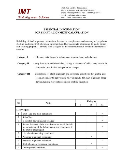
ESSENTIAL INFORMATION<br />
FOR SHAFT ALIGNMENT CALCULATION<br />
Reliability of shaft alignment calculations depends on completeness and accuracy of propulsion<br />
shafting modeling. Shaft alignment designer should have complete information to model propulsion<br />
shafting properly. There are three Category of essential information for shaft alignment calculation:<br />
Category I – obligatory data, lack of which renders impossible any calculations.<br />
Category II – very important additional data, taking in account of which may results in<br />
substantial quantitative and qualitative changes.<br />
Category III – descriptions of shaft alignment and operating conditions that enable goalseeking<br />
behavior to derive more relevant results for shaft alignment procedure<br />
and ensure more safe propulsion shafting operation.<br />
Pos Name<br />
I. GENERAL<br />
Category<br />
I II III<br />
1 Ship Type and main particulars *<br />
2 Ship Class *<br />
3 Is the ship newbuilded or repaired *<br />
4 Set out the cause of the propulsion train repair including<br />
description of the failure nature and conditions, if<br />
the ship is under repair<br />
*<br />
5 List of main operating conditions *<br />
6 Assumed alignment conditions *<br />
7 Assumed alignment technique *<br />
8 Shaft alignment procedure limitations *<br />
9 Other special conditions *
Essential information for shaft alignment calculation 2<br />
II. SHAFTING<br />
1 General Arrangement of propulsion train *<br />
2 Drawings of the shafts specifying their lengths and diameters<br />
3 Masses and center of gravity for heavy equipment associated<br />
with the shafting<br />
4 Information about filling of the shaft bore (oil, rods<br />
etc.)<br />
5 Information regarding propeller shaft liner (material,<br />
thickness, length and position)<br />
III. BEARINGS<br />
1 Stern tube drawing *<br />
2 Material and dimensions of the stern tube bearing<br />
bushes<br />
3 Stern tube bearing lubricator (water, oil) *<br />
4 Permissible loads (nominal pressure) for intermediate<br />
bearings specified by manufacturer<br />
5 If permissible loads for intermediate bearings are unknown<br />
material and dimensions of bearing bushes<br />
6 Thermal growth at the bearings place *<br />
7 Compliance of the bearings’ stools *<br />
8 Wear down rate *<br />
IV. PROPELLER<br />
1 Weight in the air *<br />
2 Material *<br />
3 In the case of CPP weight of the blades and hub volume<br />
(hub dimensions) or propeller weight in the water<br />
4 Percent of submergence during shaft alignment *<br />
5 Percent of submergence in operation if not 100% *<br />
6 Vertical and horizontal hydrodynamic moments in operation<br />
(or thrust value and eccentricities)<br />
V. ENGINE<br />
1 Type *<br />
2 Static thrust load Diagram (for low speed engines) *<br />
3 Deflectional and angular compliances at the thrust-shaft<br />
flange (for low speed engines)<br />
4 Crankshaft dimensions, allowable loads for engine<br />
bearings and allowable stress in crankshaft if data of<br />
item 2, 3 for low speed engines are not available<br />
*<br />
*<br />
*<br />
*<br />
*<br />
*<br />
*<br />
*<br />
*<br />
*<br />
*
Essential information for shaft alignment calculation 3<br />
5 Weight of flywheel *<br />
6 Thermal growth *<br />
7 Additional loads on crankshaft in operation *<br />
VI. GEAR BOX<br />
1 Output shaft drawing specifying shaft lengths and diameters<br />
2 Weight of the wheel *<br />
3 Permissible loads for gear box bearings specified by<br />
manufacturer in static and dynamic conditions<br />
4 Allowable difference of loads on output shaft bearings<br />
in the case of plain bearings<br />
5 Thermal growth *<br />
6 For one pinion helical gear:<br />
− Power of pinion<br />
− Pitch diameter of wheel<br />
− Speed of wheel<br />
− Transverse pressure angle of gear wheel<br />
− Helix angle of gear<br />
VII. COUPLINGS AND SLEEVES<br />
1 Weight and center of gravity *<br />
2 Allowable misalignment for flexible couplings *<br />
3 Angular and radial compliance for flexible couplings *<br />
VIII. HULL<br />
1 General arrangement and double bottom plan for engine<br />
room<br />
1 Scantlings of double bottom structure elements *<br />
2 Draughts for main operating conditions including full<br />
load and ballast conditions<br />
*<br />
*<br />
*<br />
*<br />
*<br />
*


