
You also want an ePaper? Increase the reach of your titles
YUMPU automatically turns print PDFs into web optimized ePapers that Google loves.
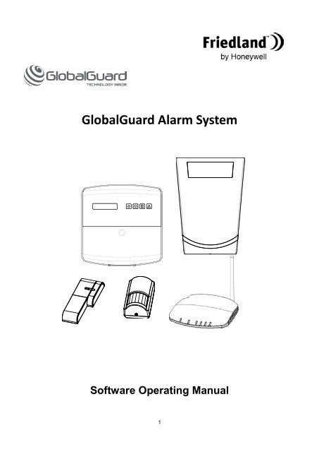
GlobalGuard Alarm System<br />
Software Operating Manual<br />
1
CONTENTS<br />
SYSTEM REQUIREMENTS AND 3<br />
FUNCTION OVERVIEW<br />
IMPORTANT NOTE WHEN RUNNING<br />
SOFTWARE 4<br />
GlobalGuard PC Setup Software<br />
Operating Instructions 5<br />
1. Instructions for installation 5<br />
2. GlobalGuard PC Setup Software 5<br />
Operating Instructions<br />
2-1 Control Panel PIN code and changing 5<br />
2-2 Home Page 6<br />
2-2-1 Show device information 6<br />
2-2-2 Configuring Programme Key 7<br />
2-2-3 Executing a Programme key 7<br />
2-3 Sync 8<br />
2-4 Event Log 8<br />
2-5 Add Device 9<br />
2-5-1 Add New Device 9<br />
Part-Arm I/II setup of security<br />
device 10<br />
2-5-2 Replace Device 11<br />
2-6 Settings 12<br />
2-6-1 Programmes 12<br />
2-6-1-1 Adding a new Programme 13<br />
2-6-1-2 Maintaining Programme 13<br />
2-6-2 Event 14<br />
2-6-2-1 Adding New Event 14<br />
2-6-2-2 Maintaining Event 14<br />
2-6-3 Schedule 17<br />
2-6-3-1 Adding New Schedule 17<br />
2-6-3-2 Mainitaining Schedule 17<br />
2-6-4 Device 19<br />
2-6-5 System 20<br />
2-6-5-1 User 20<br />
2-6-5-2 Siren 20<br />
2-6-5-3 Time and date setup 21<br />
2-6-5-4 Control Panel 21<br />
2-6-5-5 <strong>Friedland</strong> Spectra 21<br />
Lighting Controller (Optional)<br />
3. Exiting the software 21<br />
2<br />
GlobalGuard Remote Access Web Software<br />
1. Registration process 22<br />
2. Home page 22<br />
3. Security page 22<br />
4. Home Automation page 23<br />
5. Video Playback page 23<br />
6. Camera View 24<br />
7. Settings 24<br />
- Camera Settings 24<br />
- Contact Settings 24<br />
- Account Settings 24<br />
8. Resetting the password 25<br />
GlobalGuard Remote Access App 26<br />
GlobalGuard Camplay software 27<br />
Troubleshooting 30<br />
Notes (Password record) 32
SYSTEM REQUIREMENTS<br />
AND FUNCTION OVERVIEW<br />
1. The HISK1 kit should be installed as a<br />
minimum to use any of the software<br />
2. Requirements for PC setup software:<br />
- PC Operating system: Windows XP /<br />
Windows 7<br />
- CPU: Core 2 Duo<br />
- RAM: 2GB<br />
- Hard Drive space: 20GB (requires at least<br />
20G of space available on your PC’s hard<br />
drive to install the drivers, Microsoft .Net<br />
Framework and Globalguard PC<br />
software)<br />
- Not compatible with Apple MAC PCs<br />
3. Requirements for remote web access:<br />
- Unrestricted home broadband internet<br />
connection<br />
- Wired/Wireless WIFI router with x2 spare<br />
LAN ports (x1 for IP gateway and other for<br />
an optional IP Camera if added in future)<br />
- PC Operating System:<br />
Windows XP/Vista/Window7<br />
- Internet Explorer 6.x or higher Internet<br />
Web Browser<br />
- CPU: Pentium 4, 1GHz or above<br />
- VGA Card Resolution: 800x600 or above<br />
- Video Memory Size: 128Mb or above<br />
- Recommended internet upload speed<br />
512kbp/s for 1 x IP Camera (optional<br />
HIS5A product) or 2Mbp/s for 8 x IP<br />
cameras connected<br />
4. The GlobalGuard PC setup software is used<br />
to do the following:<br />
- configure the system settings in the system<br />
- adding devices to the system<br />
- set up home automation controls<br />
- operate function keys I/II/III from when you<br />
are in your home while the software is open<br />
5. The GlobalGuard online remote access web<br />
software at;<br />
https://GlobalGuard.<strong>Friedland</strong>.co.uk<br />
is used to do the following when your PC is<br />
connected to the internet and you have<br />
created an online account:<br />
- control the security functions (i.e, arm/disarm)<br />
and check status<br />
- activate home automation programmes<br />
- view/playback up to 8 CCTV cameras (when<br />
optional camera(s) added to system)<br />
- setup accounts and email contacts<br />
3<br />
6. Mobile devices compatible with the<br />
GlobalGuard remote access App:<br />
- Apple IOS: iPhone1/2/3/4, iPad1/2, iPod<br />
Touch 4<br />
- Android: Android phone V2.X, tablet PC<br />
up to V4.0<br />
7. Accessible and configurable Control Panel<br />
settings include:<br />
- Home automation Programmes:<br />
Supports up to 16 programmes.<br />
- Home automation Events:<br />
Supports up to 32 events.<br />
- Home automation Schedules:<br />
Supports up to 32 schedules.<br />
- Event Log: Browse the Control Panel<br />
event log.<br />
Supports up to 100 events.<br />
- Device Setup:<br />
- Security Devices:<br />
(1)Remotes / Detectors: for security<br />
transmitting devices; supports<br />
following devices<br />
• Up to 32 wireless PIR<br />
movement<br />
detectors and or Magnetic<br />
door/window contact detectors<br />
• Up to 8 Remote controls<br />
• Up to 6 Remote Keypads<br />
• Smoke detectors and so forth.<br />
- Home Automation devices<br />
Control: for Home Automation receiver<br />
devices; supports configurations for up<br />
to 32 devices including Plugin /<br />
Bayonet lamp holders and so forth.<br />
- System Setup:<br />
1). User: User settings; supports up to<br />
6 online users including “Admin”.<br />
2). Siren: Siren settings and Test.<br />
3). Time: the Control Panel time<br />
settings.<br />
4). Control Panel: Control Panel<br />
settings.<br />
5). Spectra Lighting Settings – For<br />
optional <strong>Friedland</strong> Spectra receiver<br />
module
IMPORTANT NOTE WHEN RUNNING<br />
SOFTWARE<br />
Ensure the correct time/date has been set on<br />
the Control Panel to allow you to view the<br />
correct system date/time in different areas of<br />
the system such as the event log and live view<br />
CCTV. For setup please refer to pages 20-21.<br />
The PC setup software should not be operated in<br />
parallel with the online remote access web software or<br />
the mobile App. By doing so will prevent yourself or<br />
other home users from remotely viewing/controlling the<br />
security/home automation functions from the online<br />
web software or App.<br />
If the PC software is loading or running, then the 2 nd RF<br />
(wireless communication to Control Panel) LED on the<br />
IP gateway will turn orange colour and will prevent the<br />
system feeding back the current system status in the<br />
online web software<br />
Remember to “Sync” to save all settings made in the<br />
PC setup software and exit it before running the online<br />
web remote access software<br />
4
GlobalGuard PC Setup Software<br />
1. Instructions for installation:<br />
In order to use the PC setup software, your PC must be<br />
connected to the internet to download the free software<br />
from: www.GlobalGuard.<strong>Friedland</strong>.co.uk:<br />
1. Install the PC software step by step after<br />
downloading it. Your PC may also require updating<br />
to Microsoft .Net Framework V4.0 which is<br />
automatically done during the installation.<br />
2. Ensure your Control Panel and IP gateway both<br />
remain powered on. Your PC must also be<br />
connected wired or wirelessly to the same<br />
broadband router that the IP gateway is<br />
connected to (see the figure below). If<br />
wirelessly connected ensure it is within WIFI<br />
range of the wireless router<br />
Gateway Router<br />
PC<br />
Note:<br />
1) Ensure that both the router and PC are<br />
configured to have DHCP function enabled.<br />
2) If the data transfer speed is too slow or seems<br />
to stop, check the network firewall setting. If<br />
the firewall is enabled, disable the firewall<br />
temporarily to allow data transfer.<br />
3. Double-click the “GlobalGuard” shortcut icon<br />
shown below on your PC desktop.<br />
5<br />
2. GlobalGuard PC Setup Software<br />
Operating Instructions<br />
When you attempt to configure the Control Panel via<br />
GlobalGuard PC setup software, please take note of<br />
the following during the process:<br />
1. Do not configure the Control Panel using its<br />
keypad while the GlobalGuard software is still<br />
running as this may result in data inconsistency.<br />
2. With the exception of actions such as Add Device<br />
/ Replace Device / Remove Device, in order for<br />
other settings to take effect, the Sync function<br />
must be used to apply the new settings to the<br />
Control Panel.<br />
When you double click the GlobalGuard desktop icon,<br />
the system will automatically check to see if the IP<br />
Gateway has been connected to the network. If the IP<br />
Gateway has been found, the system will automatically<br />
access relevant data from the Control Panel. The<br />
process could take up to a few minutes; please wait for<br />
the system to read the data. Note: The 2 nd LED (RF<br />
indication) on the gateway will change from green<br />
to orange colour while the PC software is loading<br />
and during use of the software<br />
2-1 Control Panel PIN code and changing<br />
The user access PIN code is used to access the<br />
Control Panel for either programming or controlling it.<br />
Once the system has finished reading the data, the<br />
system will prompt the user for Admin PIN code.<br />
Please note that in order to operate the system, you<br />
must enter the correct Admin PIN code. The factory<br />
preset Admin PIN code for the Control Panel is “1234”.<br />
For security reasons, it is recommended that once you<br />
log into the system, go to Settings – System – User<br />
and change the default Admin PIN code.<br />
You will be taken to the main operating screen after the
system has validated the PIN code you have entered.<br />
The GlobalGuard system is made up of 5 primary<br />
functional modules, namely:<br />
Home Page<br />
Sync<br />
Event Log<br />
Add Device<br />
Settings<br />
CUSTOMER HELPLINE<br />
Most issues can be solved over the phone in a few minutes.<br />
Please contact our Helpline Team on the number below for any<br />
installation and general advice regarding our products:<br />
<strong>0844</strong> <strong>736</strong> <strong>9149</strong><br />
Lines open 9.00am to 5.00pm, Monday to Friday.<br />
Calls charged at service providers national rate.<br />
6<br />
2-2. Home Page<br />
Main functions you will find under “Home Page”<br />
include:<br />
1-1 Show device information<br />
1-2 Configure a Programme Key.<br />
1-3 Execute a Programme Key.<br />
2-2-1. Show device information<br />
Click on any device to access a window (see below)<br />
that contains specific information about the device,<br />
such as Device Name, Device Type, Number, Location<br />
and so forth.<br />
Examples:<br />
When you click , the system will display this<br />
message window.<br />
When you click , the system will display this<br />
message window.
2-2-2. Configuring the Programme Keys<br />
Please take note of the following when you configure<br />
Programme Keys:<br />
1. The Programme Keys I/II/III correspond to<br />
the Function key buttons I/II/III on the Control<br />
Panel, which means clicking the Programme<br />
Key I in the software interface or pressing the<br />
Function Key I on the Control Panel will<br />
activate the same Programme.<br />
2. To configure a Programme Key, you should<br />
assign an existing Programme (or create a<br />
new Programme and designate it) to<br />
Programme Key I, II, or III.<br />
3. If you have designated a Programme to a<br />
specific Programme Key previously, you will<br />
not be able to designate said Programme to<br />
another Programme Key.<br />
4. For information about configuring a new<br />
Programme or maintaining an existing<br />
Programme, refer to Setting – Programmes.<br />
Follow the steps described below to reconfigure<br />
Programme Keys:<br />
1. Click [Home Page] in the Top Menu.<br />
2. Click on the [Living1] icon or any other available<br />
programme that may have been created as described<br />
later in this manual:<br />
7<br />
3. The system will display a small function menu above<br />
the icon and you can specify the location of the<br />
programme key. In this example, [I] has been chosen<br />
and this means Programme Key [I] has been redefined<br />
to [Living1].<br />
4. After you have reconfigured the Programme Key,<br />
you will see [I] over [Living1].<br />
5. Remember that after you have finished a<br />
configuration, you must select the Sync function to<br />
apply the new settings to the Control Panel in order for<br />
the changes to take effect particular when trying to<br />
execute any of the blue Programme keys on the home<br />
page.<br />
2-2-3. Executing a Programme Key<br />
Click the following buttons directly in this window to<br />
execute the corresponding Programme Key:<br />
: Execute Programme Key 1<br />
: Execute Programme Key 2<br />
: Execute Programme Key 3<br />
The system will display one message window to inform<br />
the user whether the execution of the Programme is
successful or not.<br />
2-3. Sync<br />
i.e.: Programme executed successfully<br />
The PC setup software is intended as an assistive<br />
program for the Control Panel setup. Setup is only<br />
complete after all the settings made on your PC have<br />
been applied to the Control Panel with the Sync<br />
function. Therefore it is imperative that the user sync<br />
the PC with the Control Panel after each modification<br />
of settings. If you close the PC software during setup,<br />
the Control Panel will not recognize any configuration<br />
you have made, with exception of “Add<br />
Device/Remove Device”. (These two actions take<br />
effect immediately.)<br />
To Sync,<br />
1. Select [Sync] in the Top Menu.<br />
2. Click the button located<br />
at the lower right hand corner of the<br />
screen.<br />
The system will send the updated settings to the<br />
Control Panel. It is recommended that you perform this<br />
operation immediately after each settings change to<br />
ensure the data in the Control Panel is always<br />
up-to-date.<br />
The Sync window (see below) will appear whenever<br />
the system is writing data back to the Control Panel,<br />
indicating that the system is in the process of<br />
8<br />
synchronizing.<br />
Important note during Syncing:<br />
When data is being synced to the Control Panel,<br />
any security functions and home automation<br />
Programmes, Schedules, and Events will not<br />
operate during this period.<br />
2-4. Event Log<br />
The event log is a record of all activities executed by<br />
the Control Panel. This is primarily captured and stored<br />
in the Control Panel itself.<br />
The Event Log function is used to retrieve the latest<br />
event log from the Control Panel in the current window<br />
on your PC.<br />
Click the above button to load the latest event log from<br />
the Control Panel and display it on screen.<br />
The window (see below) will appear when the system<br />
is loading event log from the Control Panel, indicating<br />
that the system is in the process of synchronizing.
After the system has finished loading the latest event<br />
log from the Control Panel, it will be promptly displayed<br />
in the window.<br />
The event log consists of the following information:<br />
Time The date and time of the event.<br />
Location The place where the event<br />
happened. For instance, if a PIR<br />
detector assigned to Bedroom is<br />
triggered, the location column will<br />
show “Bedroom”.<br />
Device/User<br />
/Action<br />
This column displays what or who<br />
triggered the event.<br />
Name If the event is triggered by a user,<br />
this column will display the name of<br />
the User (such as Admin or<br />
User1…).<br />
Message This column shows the content of<br />
the event.<br />
9<br />
2-5. Add Device<br />
There are two ways to add new devices to the system;<br />
using the Control Panel (refer to Hardware manual) or<br />
using the GlobalGuard PC setup software. The PC<br />
software provides an intuitive interface so the user can<br />
add devices more easily.<br />
Note: The first two wireless security devices (PIR<br />
movement or door contact detector) added to the<br />
system will have a preconfigured 30 second<br />
entry/exit delay. It is recommended to install the 1 st<br />
detector (zone1) you add at the entry/exit point of<br />
your property<br />
The entry delay period for a security device can be<br />
setup in ‘Advance Settings’ of that device. The exit<br />
delay can be setup in ‘Settings-Device-Control<br />
Panel’ page<br />
2-5-1. Add New Device<br />
On the interface screen you can find two buttons on the<br />
left side: [Add New Device] and [Replace Device]. As<br />
their titles suggest, [Add New Device] is to add a new<br />
device to the system, while [Replace Device] is to<br />
replace an existing device with a new one. On the right<br />
side are the icons of preconfigured device groups.<br />
To add a new device, all you need to do is to click on<br />
the [Add New Device] button, and then select a desired<br />
device icon and follow the screen prompts to complete<br />
the procedures.<br />
Note: All devices with exception to the optional<br />
GlobalGuard camera can be linked and displayed<br />
in this software. The camera is not displayed here<br />
and is only linked via the GlobalGuard remote<br />
access online software.<br />
Example 1: Adding a PIR movement detector:<br />
Note: Please also refer to the Hardware manual for<br />
information on how to configure the device into<br />
learning mode.<br />
1. Click on the PIR Detector icon.
2. The software will issue a request to the Control<br />
Panel to go into code learning mode.<br />
3. Press the learn/tamper button on the selected PIR<br />
detector within 30 seconds to transmit a code to be<br />
picked up by the Control Panel.<br />
Note: See the screen prompt (also the figure below)<br />
to find out the location of the learn/tamper button<br />
on the device. After you press the learn/tamper<br />
button, the Control Panel will also beep to indicate<br />
the reception of the learning code.<br />
4. Once the system has learnt the device’s code, the<br />
device setting window will appear up for you to<br />
configure the device’s name, location, and security<br />
type:<br />
Name: Specify a name for easy identification.<br />
Location: Specify where the device is installed.<br />
Security Type: Specify the level of alarm when the<br />
device is triggered.<br />
5. After adding/replacing a security device (PIR or<br />
door/window contact detector) to the system, refit the<br />
detector in position to its battery cover before exiting<br />
the add device screen. This is will prevent the tamper<br />
alarm from initiating if the tamper button is press and<br />
release during final installation of a detector.<br />
IMPORTANT: Specify the Location of device<br />
carefully as it affects many aspects in the system:<br />
1) If one or more IP cameras are installed in your<br />
system, then when a PIR or other type of detector<br />
is triggered, the camera assigned to the SAME<br />
10<br />
location will start recording. Therefore you should<br />
plan beforehand and assign the location group<br />
carefully.<br />
2) When the device is triggered, the Web software<br />
and the smartphone app will also inform the user<br />
of the location. So the correct setting of location is<br />
critical for the information.<br />
3) After a security detector such as a wireless PIR<br />
or door contact detector has been added, the<br />
device number is the “Zone Number” (1-36)<br />
displayed at the top of the window. The zone<br />
number for each security device is stored in the<br />
Control Panel<br />
Part-ArmI/II setup of a security device<br />
All PIR movement and door/window contact security<br />
detectors can be also setup to operate with Part-Arm I<br />
or Part-Arm II security modes.<br />
If a group of detectors have been set so that they can<br />
activate in Part-Arm I, this means that when the Control<br />
Panel is armed in Part-Arm I mode, then only those<br />
detectors setup will become active. An example would<br />
be part-arming the ground floor of your home while you<br />
are gone to sleep so you can move around upstairs at<br />
night without initiating an alarm<br />
Part arm setup of a device can be done during the<br />
adding process or after the device has been added<br />
in “Settings – Devices”.
Select “Advance Setting” followed by any or both of the<br />
Part-arm-I or II selections<br />
Example 2: Adding a Home Automation device:<br />
1. Click on the On/Off Plug icon.<br />
2. The system will display the code learning prompt.<br />
3. Follow the on-screen instructions to set the selected<br />
device into learning mode.<br />
4. After the device is placed into learning mode, click<br />
the [Add Now] button on the screen.<br />
5. Wait until the Control Panel issues the learning code<br />
command, and the code learning process for the<br />
device is complete.<br />
6. The Control Panel will issue test commands, and<br />
you should see the selected lighting device go on and<br />
off to demonstrate that code learning has been<br />
properly completed.<br />
7. The system will promptly bring up the device setting<br />
window for you to configure the device’s properties.<br />
11<br />
2-5-2. Replace Device<br />
When you click the [Replace Device] on the left side, all<br />
existing devices will be displayed on the right panel. To<br />
replace a device, simply click on an icon and follow the<br />
screen prompts to complete the procedures. This<br />
function is useful whenever a device has become faulty.<br />
You can simply purchase the same device and use this<br />
function to replace the faulty one without having to<br />
make any configurations. The device will operate and<br />
function according to your previous settings.<br />
Example: Replacing a PIR movement detector.<br />
CUSTOMER HELPLINE<br />
Most issues can be solved over the phone in a few minutes.<br />
Please contact our Helpline Team on the number below for any<br />
installation and general advice regarding our products:<br />
<strong>0844</strong> <strong>736</strong> <strong>9149</strong><br />
Lines open 9.00am to 5.00pm, Monday to Friday.<br />
Calls charged at service providers national rate.
1. Click on the PIR movement detector icon.<br />
2. The software will issue a request to the Control<br />
Panel to go into learning mode.<br />
3. Operate the learn/tamper button on the selected PIR<br />
device within 30 seconds to transmit a code to be<br />
picked up by the Control Panel.<br />
4. Once the system has learnt the device’s code, the<br />
device setting window will appear for you to configure<br />
the device’s properties. Refer to the previous section<br />
for details of the setting items.<br />
12<br />
2-6. Settings<br />
Concept of Programmes, Schedules and Event<br />
There are three ways to control home automation<br />
devices using the GlobalGuard system:<br />
Programmes : A Programme is a set of action(s) that<br />
are activated immediately when called upon by the<br />
user. These actions may include turning on/off the<br />
plugs, or changing the security mode of the control<br />
panel. Programmes can be assigned into Function<br />
keys I, II and III on the Control Panel so that they are<br />
activated when user presses those keys via the Control<br />
Panel, the home page of the PC setup software or via<br />
the online remote access software.<br />
Events : An Event is a set of multiple actions that take<br />
place when the system is triggered by a detector. For<br />
example, an Event can be created to automatically turn<br />
on the porch lamp (connected to a ON/OFF device)<br />
when the door/window contact detector detects the<br />
front door opening. Unlike Programmes, Events are<br />
activated by detectors rather than activated upon<br />
request by the user.<br />
An Event can also be set to be triggered by a change in<br />
the security settings. For example, setting the Control<br />
Panel to ARM remotely through the website can turn on<br />
the light to warn off intruders.<br />
Schedules : A Schedule is a set of multiple actions that<br />
are activated when the preset time is reached. For<br />
example, one can create a Schedule to turn ON a table<br />
lamp connected to a ON/OFF plug at 6pm and OFF at<br />
11pm on a daily basis or particular days.<br />
2-6-1. Programmes<br />
To create or maintain a Programme, select [Settings] in<br />
the top menu and click “Programmes” in the menu to<br />
the left. The system supports up to a maximum of 16<br />
Programmes and once you have reached the<br />
maximum, the [Add New Programme] button will turn<br />
grey.
2-6-1-1. Adding a new Programme<br />
Click [Add New Programme] when you wish to add a<br />
new Programme to the system. The system will bring<br />
up the Setting – Programme – New Programme<br />
window for you to edit relevant details. For more<br />
information on Programme maintenance, refer to the<br />
section below 2-6-1-2 on “Maintaining Programmes”.<br />
Note: For detailed information on assigning a<br />
programme to a Programme Key, which<br />
correspond to a Function Key on the Control Panel,<br />
please refer to page 7.<br />
Example of Programmes could be using Function key I<br />
to activate a group of ON/OFF plug/lampholder devices<br />
ON and Function Key II to turn these OFF if pressed.<br />
Function key III to arm your system and turn ON an<br />
ON/OFF device at the same time, etc.<br />
2-6-1-2. Maintaining Programmes<br />
To maintain an existing Programme, simply click on the<br />
icon of the desired Programme to access the<br />
Programme maintenance screen. You can choose up<br />
to 16 actions to be taken in a single Programme,<br />
including Sound (audio), Step1 (Control Panel security<br />
mode) and Step2 (customized Home Automation<br />
control actions) and so forth. The system will keep tally<br />
on the actions that you have configured and once you<br />
have configured 16 actions for a Programme, the<br />
system will lock the action setting mode and you will<br />
only be able to disable actions but not add new ones<br />
when that happens.<br />
CUSTOMER HELPLINE<br />
Most issues can be solved over the phone in a few minutes.<br />
Please contact our Helpline Team on the number below for any<br />
installation and general advice regarding our products:<br />
<strong>0844</strong> <strong>736</strong> <strong>9149</strong><br />
Lines open 9.00am to 5.00pm, Monday to Friday.<br />
Calls charged at service providers national rate.<br />
13<br />
The following section will cover relevant Programme<br />
maintenance information:<br />
Name: Programme Name; you may create a name for<br />
the selected Programme for easy identification.<br />
Number: Denotes the number of Programme currently<br />
available on the system; you can have up to a<br />
maximum of 16 Programmes.<br />
Icon: You can change the default icon into any other<br />
icon you prefer (the file extension for the icon must be<br />
in “.ico”).<br />
Sound: Enable sound effect playback by the Control<br />
Panel; you can choose ‘None’ or Chime sound.<br />
Programme: Shows the status of the selected<br />
Programme; click “Enable” to activate the Programme<br />
and “Disable” to deactivate it.<br />
Step1: Configure the type of security mode for the<br />
Control Panel to employ.<br />
1. No Setting: Use the current security mode set<br />
for the Control Panel without making any<br />
change.<br />
2. Fully Arm: the Control Panel will go into “Fully<br />
Arm” security mode.<br />
3. Part-Arm-I: the Control Panel will go into<br />
“Part-Arm-I ” security mode. You can check to<br />
see the acting zone detectors under “Intruder<br />
Detector” to find out which zone detectors will be<br />
activated in this security mode.<br />
4. Part-Arm-II: the Control Panel will go into<br />
“Part-Arm-II ” security mode. You can check to<br />
see the acting zone detectors under “Intruder<br />
Detector” to find out which zone detectors will be<br />
activated in this security mode.<br />
5. Disarm: the Control Panel will disable security<br />
mode.<br />
6. Holiday Arm: the Control Panel will go into<br />
“Holiday Arm” security mode.<br />
Step2: Configure the type of action for Home<br />
Automation controllers to take.<br />
1. No Action: No action taken on any ON/OFF<br />
home automation receiver device.<br />
2. All On: Home Automation controllers will turn<br />
on all ON/OFF receiver devices that have had<br />
their “All On” option checked under Home<br />
Automation setting.<br />
3. All Off: Home Automation controllers will turn<br />
off all ON/OFF receiver devices.<br />
4. Individual: Home Automation controllers will<br />
perform the action that the user has selected<br />
and customized (Turn On/Off…) for<br />
corresponding ON/OFF receiver devices.<br />
: Click this button and the system will display<br />
where the selected Programme is applicable for your
eference.<br />
Example:<br />
Click and the following window will pop up.<br />
This means that the selected Programme is used in<br />
Schedule 01 [Demo].<br />
2-6-2. Event<br />
To create or maintain an Event, select [Setting] in the<br />
Top Menu and click [Event] in the menu to the left. The<br />
system supports up to a maximum of 32 Events and<br />
once you have reached the cap, the [Add New Event]<br />
button will turn grey.<br />
14<br />
2-6-2-1. Adding New Event<br />
Click [Add New Event] when you wish to add a new<br />
Event to the system. The system will bring up the<br />
Setting – Event – New Event window for you to edit<br />
relevant details. For more information on Event<br />
maintenance, refer to section 2-6-2-2 on “Maintaining<br />
Events” below.<br />
2-6-2-2. Maintaining Events<br />
To maintain an existing Event, simply click on the icon<br />
of the desired Event to access the Event maintenance<br />
screen. Please note that an Event must comprise a<br />
detector/device trigger and Activate Actions<br />
The following section will cover relevant Event<br />
maintenance information:<br />
Name: Event Name; you may create a name for the<br />
selected Event for easy identification.<br />
Number: Denotes the number of Events currently<br />
available on the system; you can have up to a<br />
maximum of 32 Events.<br />
Step1: Specify trigger method (Device Triggered or<br />
System Triggered)<br />
1. Setting an Event to be Device Triggered:<br />
(1) Device Trigger: You can specify the device<br />
(i.e Zone Detector / Device / Keypad /<br />
Remote that the system has learnt) to be<br />
triggered and the type of action that will<br />
trigger it.<br />
(2) Specify the security mode for the trigger to<br />
take effect. By default, the trigger will be<br />
applied to all security modes. This<br />
configuration is only needed when you have<br />
selected Device Trigger.<br />
(3) Specify the valid time for the trigger. By<br />
default, the trigger will be valid 24 hours<br />
around the clock.<br />
If the time for “from” is identical to the time<br />
for “to”, the trigger will remain active<br />
throughout the day (i.e. 00:00 ~ 00:00)<br />
If the time for “from” is greater than the time<br />
for “to”, the trigger will be active between the<br />
changes of calendar days (i.e. 22:00 ~<br />
08:00)<br />
If the time for “from” is smaller than the time<br />
for “to”, the trigger will be active during the<br />
specific time on a daily basis (i.e. 08:00 ~<br />
22:00)
Example: Device Trigger<br />
2. Setting an Event to be System Triggered.<br />
(1) System Trigger: You can specify which<br />
system security mode the event will operate<br />
with when activated<br />
(2) Specify the valid time for the trigger. By<br />
default, the trigger will be valid 24 hours<br />
around the clock.<br />
If the time for “from” is identical to the time<br />
for “to”, the trigger will remain active<br />
throughout the day (i.e. 00:00 ~ 00:00)<br />
If the time for “from” is greater than the time<br />
for “to”, the trigger will be active between the<br />
changes of calendar days (i.e. 22:00 ~<br />
08:00)<br />
If the time for “from” is smaller than the time<br />
for “to”, the trigger will be active during the<br />
specific time on a daily basis (i.e. 08:00 ~<br />
22:00)<br />
Example: System Trigger<br />
Step2: Specify the action to be taken when the<br />
trigger has been set off.<br />
15<br />
You can configure the system to take one of the<br />
following two actions:<br />
1. Control Device: the system will take whatever<br />
action(s) you have configured for Control<br />
Device, including Sound. You can configure<br />
up to 16 actions.<br />
2. Programmes: the system will execute the<br />
selected Programme.<br />
Example: Configuring the system to Control Device<br />
when the trigger has been set off.<br />
Example: Configuring the system to execute a<br />
preselected Programme.<br />
Note: If System Trigger has been set as the source of<br />
trigger, ensure the selected Programme does not<br />
involve actions that will toggle the change of security<br />
modes. When the system identifies such conflicting<br />
configuration, it will disable the Programme and render<br />
it unavailable to the user. Refer to the following<br />
example:
Example: Using System Trigger<br />
As you can see in this example, all Programmes have<br />
been disabled by the system. This means that all of<br />
the Programmes available involve the change of the<br />
Control Panel security modes.<br />
Example: This is what will happen if you try to skip<br />
ahead to Step2 and have the system execute the<br />
Programmes. In this example, we will select<br />
Programme1.<br />
When you go back to Step1, you will find that “System<br />
Trigger” has been made unavailable. This means that<br />
the Programme that was selected previously involve<br />
16<br />
the change of the Control Panel security modes.<br />
Step3: Specify the duration of delay time for Action<br />
2 to be executed (Optional)<br />
Example: Setting the delay time to 5 seconds before<br />
Action 2 is executed.<br />
Step4: Activate Action 2 (Optional)<br />
The steps and rules for Action 2 are identical to what<br />
have been covered for Action 1. Refer to the<br />
descriptions for Action 1 if needed.<br />
If you wish to simplify the configuration process, simply<br />
complete the settings for Step1 and Step2; Steps 3 and<br />
4 are optional.
2-6-3. Schedule<br />
To create or maintain a Schedule, select [Setting] in the<br />
top menu and click [Schedule] in the menu to the left.<br />
The system supports up to a maximum of 16<br />
Schedules and once you have reached the maximum,<br />
the [Add New Schedule] button will turn grey.<br />
2-6-3-1. Adding New Schedule<br />
Click [Add New Schedule] when you wish to add a new<br />
Schedule to the system. The system will bring up the<br />
Setting – Schedule – New Schedule window for you to<br />
edit relevant details. For more information on Schedule<br />
maintenance, refer to section 2-6-3-2 below on<br />
“Maintaining Schedules”.<br />
Example of a schedule might be activating an ON/OFF<br />
plugin device to turn ON a table lamp on a daily basis<br />
between 7pm and 11pm whilst you are away from your<br />
home.<br />
2-6-3-2. Maintaining Schedules<br />
To maintain an existing Schedule, simply click on the<br />
icon of the desired Schedule to access the Schedule<br />
maintenance screen.<br />
The following section will cover relevant Event<br />
maintenance information:<br />
Name: Schedule Name; you may create a name for the<br />
selected Schedule for easy identification.<br />
Number: Denotes the number of Schedules currently<br />
available on the system; you can have up to a<br />
maximum of 16 Events.<br />
Step1<br />
Specify trigger mode (Fixed Time and Weekly).<br />
1. Setting a Schedule to be triggered at Fixed Time:<br />
1-1. Set Action Time: Specify the time for the<br />
17<br />
Schedule to be triggered.<br />
1-2. Specify the security mode for the trigger to<br />
take effect. By default, the trigger will be<br />
applied to all security modes.<br />
2. Setting a Schedule to be triggered Weekly:<br />
1-1. Set Action Time: Specify the time for the<br />
weekly trigger.<br />
1-2. Specify the security mode for the trigger to<br />
take effect. By default, the trigger will be<br />
applied to all security modes.<br />
Step2<br />
Specify the action to be taken when the trigger has<br />
been set off.<br />
You can configure the system to take one of the<br />
following two actions:<br />
1. Control Device: the system will take<br />
whatever action(s) you have configured for<br />
Control Device, including Sound. You can<br />
configure up to 16 actions.<br />
2. Programmes: the system will execute the<br />
selected Programme.
Example: Configuring the system to Control Device<br />
when the trigger has been set off.<br />
Example: Configuring the system to execute a<br />
preselected Programme.<br />
Note: Please ensure that Programmes that involve the<br />
action of disarming security modes may not be<br />
included in a Schedule. When the system identifies<br />
such conflicting configuration, it will disable the<br />
Programme and render it unavailable to the user. Refer<br />
to the following example:<br />
Example: As you can see, Programme02 has turned<br />
grey in the following screenshot. This means that<br />
Programme02 contains action that disarms the Control<br />
Panel's security mode.<br />
18<br />
Step3: Specify the duration of delay time for Action<br />
2 to be executed (Optional)<br />
Example: Setting the delay time to 1 minute before<br />
Action 2 is executed.<br />
Step4: Activate Action 2 (Optional)<br />
The steps and rules for Action 2 are identical to what<br />
have been covered for Action 1. Refer to the<br />
descriptions for Action 1 if needed.<br />
If you wish to simplify the configuration process, simply<br />
complete the settings for Step1 and Step2; Steps 3 and<br />
4 are optional.<br />
CUSTOMER HELPLINE<br />
Most issues can be solved over the phone in a few minutes.<br />
Please contact our Helpline Team on the number below for any<br />
installation and general advice regarding our products:<br />
<strong>0844</strong> <strong>736</strong> <strong>9149</strong><br />
Lines open 9.00am to 5.00pm, Monday to Friday.<br />
Calls charged at service providers national rate.
2-6-4. Device<br />
To maintain the contents of device information, select<br />
[Setting] in the Top Menu and click [Device] on the<br />
menu to the left. You will see the devices that have<br />
completed the code learning process in the window on<br />
the right. Simply click the desired device to access the<br />
edit window.<br />
Example: The following window will appear when you<br />
click “On/Off Plug 1”.<br />
: Use this function to display which<br />
Programme(s), Event(s) or Schedule(s) it will operate<br />
with.<br />
: Use this function to remove the selected<br />
device from the Control Panel. When you use this<br />
function to remove a device, all functions that involve<br />
the use of this device will be removed as well (including<br />
Programmes, Events, Schedules). If you have to<br />
purchase a new device to replace a faulty one, it is<br />
recommended that you use the Add Device – Replace<br />
Device for the replacement. If you remove the device<br />
and add it again, you will have to reconfigure all<br />
relevant settings that you have previously made<br />
before.<br />
19<br />
: Different device types would have different<br />
advanced settings.<br />
Example: When you click , the following<br />
window will pop up.<br />
This means that the selected ON/OFF Plug is used in<br />
all the functions (represented by different icons)<br />
appearing in the window.<br />
Example: Click and the following information<br />
will be displayed.<br />
In above example (ON/OFF plug), “All On” enabled<br />
means that the device will operate when the ”All On”<br />
function is selected to operate the device in a home<br />
automation Programme, Event or Schedule
2-6-5. System<br />
You can configure the following 5 system related<br />
settings here:<br />
1. User<br />
2. Siren<br />
3. Time<br />
4. Control Panel<br />
5. Spectra Lighting Controller<br />
Details on each setting will be covered in the following<br />
section.<br />
2-6-5-1. User<br />
You can maintain various types of user information (i.e.<br />
user name and PIN code) here.<br />
For instructions on other detailed settings, please refer<br />
to the hardware instruction manual for the Control<br />
Panel<br />
Note:<br />
1. The PIN code for Admin may not be<br />
left blank. This restriction does not<br />
apply to other users.<br />
2. To avoid potential confusion and<br />
difficulty in user management,<br />
identical PIN codes shared by two or<br />
more users will not be accepted.<br />
3. PIN codes must 4 digits in length.<br />
4. When a user does not have a valid<br />
PIN code or a remote, they will be<br />
shown as “Disable” on the list to the<br />
left.<br />
20<br />
: If a user is in possession of a remote, a<br />
remote control icon will appear next to the user in the<br />
edit window.<br />
2-6-5-2. Siren<br />
You can configure relevant Siren settings here.<br />
For instruction on other detailed settings, please refer<br />
to the hardware instruction manual for the Control<br />
Panel<br />
CUSTOMER HELPLINE<br />
Most issues can be solved over the phone in a few minutes.<br />
Please contact our Helpline Team on the number below for any<br />
installation and general advice regarding our products:<br />
<strong>0844</strong> <strong>736</strong> <strong>9149</strong><br />
Lines open 9.00am to 5.00pm, Monday to Friday.<br />
Calls charged at service providers national rate.
2-6-5-3. Time and date setup<br />
You can configure the time and date on the Control<br />
Panel here.<br />
: Click to sync the fields with your PC’s current<br />
date and time.<br />
Example: The system will automatically fill in the<br />
current date and time on your PC into the<br />
corresponding fields when you click .<br />
2-6-5-4. Control Panel<br />
You can configure relevant settings for the Control<br />
Panel here.<br />
For instruction on other detailed settings, please refer<br />
to the hardware instruction manual for the Control<br />
Panel available at www.GlobalGuard.<strong>Friedland</strong>.co.uk<br />
21<br />
2-6-5-5. <strong>Friedland</strong> Spectra Lighting Controller<br />
(Optional)<br />
This page allows you to set the settings for the<br />
<strong>Friedland</strong> Spectra Lighting Controller.<br />
For instruction on other detailed settings, please refer<br />
to the hardware instruction manual for the Control<br />
Panel<br />
2-7. Exiting the software<br />
You will see the following prompt when you are about<br />
to exit the software.<br />
It means that you have made changes to some settings<br />
in the software but did not use the Sync function to<br />
apply the changes you have made to the Control Panel.<br />
If that is the case, click “No” and use the Sync function<br />
to apply the changes you have made to the Control<br />
Panel. If you do not wish to apply the changes you<br />
have made, click “Yes” to exit the software.<br />
Note:<br />
Please note that actions such as Add Device / Replace<br />
Device / Remove Device take effect immediately during<br />
the operation of the Control Panel and that they will<br />
remain effective even if though you may not have<br />
synchronize the software with the Control Panel.
GlobalGuard Remote Access Web<br />
Software<br />
1. Registration process<br />
In order the use the online web software at<br />
www.GlobalGuard.<strong>Friedland</strong>.co.uk , you must first<br />
register your IP gateway and create your loggin details<br />
(HomeID, AdminID and Password).<br />
1. Select [here] to begin the registration process.<br />
2. For the next window, you must enter the MAC ID that<br />
is printed on a label located on the bottom of the IP<br />
gateway.<br />
3. Follow the on screen prompts for the registration<br />
process and remember to read and accept the EULA<br />
terms and conditions.<br />
When requested, you must enter a valid email<br />
address which you are able to access, because you<br />
will need to activate your account by accessing the<br />
confirmation email that is sent and selecting a link<br />
to access the login page again.<br />
Note: By manually accessing the home page<br />
straight after registering will not allow you to<br />
access your account. You must access via the link<br />
in the confirmation email to activate the account.<br />
4. After registration is complete and you have<br />
accessed your account, it is important that you set up<br />
at least one email contact in “Settings – Contact”<br />
window to allow that contact to receive email alert<br />
notifications from the system, such as when your alarm<br />
system is triggered, etc. For details refer to page 24<br />
“Contact Settings.<br />
22<br />
2. Home page<br />
After you have logged into your account, you will enter<br />
the home page and this will display the security status<br />
of your Control Panel. If your system is armed then this<br />
will be also be shown on this page also.<br />
Remember to accept and install the activeX prompt<br />
when you first log in. This allows you to view the<br />
optional GlobalGuard CCTV camera if purchased<br />
Example of home page with admin user “MK123”<br />
logged in:<br />
The home page also displays the following information:<br />
- Which users are ‘currently logged in’<br />
- Event log of all security actions, such as<br />
arm/disarm,<br />
- Video camera icon– Indicates if the optional<br />
camera has recorded a video file assocated<br />
with that event. If it has then a camera icon<br />
will be displayed under the “Video” column .<br />
Always remember to logout after using the web<br />
software.“Logout” is locate on the top right of the<br />
window<br />
3. Security page<br />
This page is used to activate any security function;<br />
Fully Arm, Holiday Arm, Partial-Arm I/II or Disarm.<br />
Example window to “Fully Arm” the Control Panel
To activate any of the security functions;<br />
1) Select the required security function<br />
2) Select the [Apply] box<br />
3) Enter the 4 digit PIN user access code of your<br />
Control Panel from the keypad displayed<br />
4) Select [Submit] on the keypad<br />
After you have completed the request, the security<br />
status of the system will update after a short delay.<br />
Note: You may find the delay time of security<br />
control requests will vary and depending on the<br />
speed of the online server<br />
Partial-Arm I/II is used to activate any security detector<br />
that has been configured to operate with part arm I or II.<br />
By default none of the detectors are set to part-arm I or<br />
II. For details on setting up part-arm I or II for a detector,<br />
please refer to page10.<br />
Holiday Arm mode is a duplicate of Fully Arm mode.<br />
Fully Arm mode might be used daily when you<br />
commute to work for example, whereas Holiday Arm<br />
may be used when you are away on Holiday for longer<br />
period.<br />
For Holiday Arm mode particularly, you may wish to<br />
consider setting up Schedules or Events to operate<br />
home automation ON/OFF devices whilst you are away.<br />
This allows your home to simulate the presence of<br />
occupants whilst away.<br />
For details on setting up Schedules and Events with<br />
any of the arming modes, please refer to the<br />
GlobalGuard PC software setup section in this manual.<br />
4. Home Automation page<br />
This page displays all home automation programmes<br />
stored in the Control Panel. Also it is used to activate<br />
any programme instantly and remotely.<br />
You can create customized programmes using the<br />
GlobalGuard PC setup software. Please refer to the PC<br />
setup section in this manual. If any new programmes<br />
have been created, they will also be displayed in the<br />
Home Automation page ready to activate.<br />
You will also be able to see which programmes have<br />
been assigned to a function key I/II or III<br />
23<br />
Example below shows programmes that have been<br />
assigned to function keys I/II or III.<br />
Select [Run Other Scenes] to display and control any<br />
other programmes that may be stored in the Control<br />
Panel<br />
[View Activity Log] is used to display a event log of<br />
when programmes were activated by the user<br />
5. Video Playback page<br />
If you have purchased the optional GlobalGuard CCTV<br />
camera, then this page is used to list any stored video<br />
files which have been captured by the camera and<br />
allow you to playback them back individually<br />
Example screen below:<br />
CUSTOMER HELPLINE<br />
Most issues can be solved over the phone in a few minutes.<br />
Please contact our Helpline Team on the number below for any<br />
installation and general advice regarding our products:<br />
<strong>0844</strong> <strong>736</strong> <strong>9149</strong><br />
Lines open 9.00am to 5.00pm, Monday to Friday.<br />
Calls charged at service providers national rate.
For further details on the video playback functions,<br />
please refer to the manual supplied with the camera kit<br />
if purchased<br />
6. Camera view page<br />
If you have purchased the optional GlobalGuard CCTV<br />
camera(s), then this page is used to view real time<br />
video from the selected camera.<br />
For further details please refer to the manual supplied<br />
with the CCTV camera kit.<br />
Example screen below:<br />
Select the camera and click on “View” to display the<br />
live video<br />
Other functions:<br />
- REC – To manually start recording<br />
approximately a 30 second video clip<br />
- Speaker volume mute button<br />
- Speaker Volume increase/reduce<br />
- “Stop” live view<br />
7. Settings page<br />
The “Settings” window allows you to setup the<br />
following:<br />
- Camera Settings – Add up to 8 cameras<br />
or modify settings for any GlobalGuard<br />
Cameras in the system<br />
- Contact Settings – Enter up to 5 email<br />
addresses for contacting with system<br />
alerts, such as when your alarm is<br />
triggered<br />
- Account Settings – Edit admin user<br />
details and setup a further 5 users to use<br />
the online web software<br />
24<br />
Camera Settings<br />
You will need to purchase the optional GlobalGuard<br />
CCTV Camera(s) before using any of the setup<br />
features in this page. Also please refer to the camera<br />
manual for further details.<br />
Contact Settings<br />
Enter up to 5 valid email contacts for contacting in the<br />
event of alerts being sent out by the system<br />
It is important a minimum of one email contact is<br />
entered on this page.<br />
If you carry a smartphone device, then ideally you<br />
should enter the email address in your Smartphone<br />
so you can receive alerts while on the move.<br />
Example page shown below:<br />
Testing a contact added successfully:<br />
1) Enter a contact name and valid email address<br />
2) Select [Apply] to save the changes<br />
3) Select the contact from the drop down tab located<br />
next to the [Test] button<br />
4) Select [Test] to send out a test email to the email<br />
address selected and check inbox.<br />
Note: If the test email is not received in the inbox<br />
then check the junk mail folder
Account Settings<br />
The administrator (Admin user) only can edit the<br />
“Admin ID, Password and email address” details on<br />
this page. Also up to 5 further users can be added for<br />
using the online GlobalGuard web software.<br />
If adding any additional users remember to select the<br />
[Apply] button to save any changes.<br />
Example page shown below:<br />
Note:<br />
Password entered must be 8 characters<br />
All other users apart from the administrator (admin<br />
user) can not access the settings page if logged<br />
into the account for that HomeID<br />
8. Resetting the password<br />
If you have lost or forgotten your loggin password, you<br />
can reset it by selecting “Forgot your password” from<br />
the bottom of the main log in page.<br />
25<br />
Note: To reset your password you must be located<br />
in your home or ensure your PC is connected to<br />
the same network as that of the IP gateway<br />
To reset your password, you must enter your Gateway<br />
MAC ID and Admin login ID as a minimum in the<br />
following box:<br />
Follow the on screen prompts after selecting the [Next]<br />
button.<br />
The system will send out a temporary login password<br />
to the email address of the admin user.<br />
You can then access the online account again and view<br />
any login details for any users (1-5) if setup.<br />
CUSTOMER HELPLINE<br />
Most issues can be solved over the phone in a few minutes.<br />
Please contact our Helpline Team on the number below for any<br />
installation and general advice regarding our products:<br />
<strong>0844</strong> <strong>736</strong> <strong>9149</strong><br />
Lines open 9.00am to 5.00pm, Monday to Friday.<br />
Calls charged at service providers national rate.
GlobalGuard Remote Access App<br />
You can download the free “GlobalGuard” mobile<br />
device App from GooglePlay for Android devices or<br />
App/Itunes store for Apple IOS devices such as IPhone<br />
or IPad.<br />
The app is a convenient way of monitoring your home<br />
while on the move.<br />
Functions of the App include;<br />
- viewing the security status and controlling<br />
security arming/disarm functions<br />
- viewing event logs<br />
- activating programmes<br />
- viewing CCTV camera(s)<br />
- playing back any recorded video files<br />
associated with an event logs<br />
- taking instant photo snap shots and saving<br />
them to your mobile device<br />
Your mobile device must be connected to an<br />
unrestricted broadband internet connection via 3G<br />
or WIFI. Also ensure your device is within good<br />
range of the connection.<br />
Another benefit of the App is that it can be left open<br />
whilst you might be running other Apps at the same<br />
time. The app will also alert you of any system alerts<br />
such as alarm triggered, panic alarm, disarm, etc and<br />
display indications on the notification bar of the screen.<br />
If the Android App is left open then a green dot will be<br />
shown to indicate you are still signed into your system.<br />
If it is a red dot, this means the App is disconnected<br />
from your system.<br />
Points to note about the App:<br />
- If the App is left open in the background, then note<br />
that the App will reduce the battery life because it is<br />
constantly checking the status of your security<br />
system<br />
- For the Android App, always remember to press the<br />
“Exit” button in the App after you have finished<br />
using the App. Failure to do so will reduce your<br />
mobile device’s battery life.<br />
- For the Apple App, there is no exit button in the App.<br />
If the “home” button on the Apple device is pressed<br />
once then although the App may disappear, it will<br />
still be running in the background and can reduce<br />
the battery life. To close the App remember to<br />
double tap the “home” button on the device and the<br />
GlobalGuard App icon will appear at the bottom of<br />
the screen. Press and hold the icon until it wiggles,<br />
then tap the sign to close the App.<br />
- If your phone is lost or stolen whilst still logged into<br />
the App, then others may gain control of your<br />
•<br />
26<br />
system. In this case immediately change the<br />
password from the web software<br />
- Ensure your mobile device is within range of the<br />
internet connection, i.e, check the signal strength is<br />
sufficient.<br />
If using 3G connection then the security status of<br />
your system may not appear immediately after<br />
logging in due to the connection speed although the<br />
server status may appear as “Connected” to.<br />
Please wait for the security status to update. This<br />
may also be experience if connected to a WIFI<br />
connection with a weak signal on your mobile<br />
device<br />
- Do not use your mobile device to access the online<br />
GlobalGuard web software which can only<br />
accessed by Windows PC’s running internet<br />
explorer due to ActiveX control.<br />
- Up to 6 online users + admin user can log in to the<br />
system simultaneously using the App<br />
- Video files for playback from any optional CCTV<br />
camera will not all be displayed in the App. The App<br />
will only display any video files associated with any<br />
trigger events including intruder alarm, panic alarm<br />
tamper alarm and duress disarm. The video files will<br />
appear as [PLAY] next to those events in the Event<br />
log page of the App.<br />
If more than 1 camera is connected to your system<br />
then the App will only playback video from one of<br />
the cameras connected in your system.<br />
- The App is subject to be updated at any time<br />
with additional functions/features other than<br />
those listed above without any notice.
GlobalGuard Camplay software<br />
This software is used to playback video files<br />
transferred from the optional CCTV camera’s SD card<br />
on your PC. It can also convert a video file to AVI<br />
format so it can be played back from most types of<br />
media players such as Window Media Player.<br />
1. Download and install the Camplay application.<br />
2. Start the application by clicking the icon<br />
on the desktop.<br />
3. Copy the contents of the Camera’s MicroSD card<br />
on your PC:<br />
a) Remove the MicroSD card from IP Camera<br />
b) Using an SD card adapter, insert into the SD card<br />
reader on your PC.<br />
c) Copy the entire recorded folders (e.g.<br />
S@002232043-002232043) to a folder on the PC or<br />
just the desktop for example:<br />
27<br />
Open Record<br />
You can check recorded<br />
videos in the PC.<br />
Open CamPlay and select<br />
“Open Record”. Select “Browse” to open the folder<br />
containing the files<br />
Date:<br />
yyyy/mm/d<br />
Name / ID<br />
of cameras<br />
Recorded video files<br />
Show recorded files by date: yyyy mm dd on the left<br />
column.<br />
Current record folder<br />
Show directory recorded folder, and click<br />
to change directory folder.<br />
Preview video<br />
The small window on the right top will preview recorded<br />
videos according to your choice on the recorded bar.<br />
Name / ID of cameras<br />
Directory recorded folder/ Click<br />
Recorded<br />
video bar<br />
Video distribution<br />
to change folder<br />
Preview video<br />
Here will show the ID of cameras which has recorded<br />
videos according to your choice on the recorded video<br />
files.
Video distribution figure<br />
Here will show the recorded time within 24 hours, 12<br />
hours, 6 hours, 1 hours, 15 minutes, and 1 minute.<br />
Recorded video bar<br />
This displays how long a Camera(s) has recorded<br />
videos for. According to three colors, each color<br />
represents different recording types: blue-always<br />
recording, red-motion detection recording,<br />
green-schedule recording.<br />
To Playback a recording<br />
Click on the file, select the Cam Name, click on the<br />
PLAY button, and then video will be played back.<br />
1. Select File<br />
2. Select camera<br />
3. Click “Play”<br />
Below is an example of the format during play back of<br />
the recorded video selected:<br />
28<br />
CamPlay Functions<br />
Directory<br />
Directory:<br />
Language<br />
Click to get into the directory settings dialog for<br />
recording. Click “ ” to change the settings.<br />
Language: Click to select the required language:<br />
CUSTOMER HELPLINE<br />
Most issues can be solved over the phone in a few minutes.<br />
Please contact our Helpline Team on the number below for any<br />
installation and general advice regarding our products:<br />
<strong>0844</strong> <strong>736</strong> <strong>9149</strong><br />
Lines open 9.00am to 5.00pm, Monday to Friday.<br />
Calls charged at service providers national rate.
Headline Explanation:<br />
CamPlay<br />
Version<br />
Current date and time<br />
Convert video file to AVI format<br />
Converting to avi format is supported. When playing<br />
back the recorded video, select “Start time”. Decide<br />
how long the recorded video you want to convert, and<br />
left click “Stop time” and select “Convert ”.<br />
Select the directory folder to save the AVI file into:<br />
Select the [Convert] button shown above<br />
Wait for a while and the converted file will be saved in<br />
the directory folder selected.<br />
Select “Open folder” to browse all the files recorded in<br />
the same day from the same camera.<br />
Playback Function Bar<br />
Minimize CamPlay<br />
Exit CamPlay<br />
Maximize<br />
CamPlay<br />
To playback the recorded file, you can either double<br />
click on it or drag it to the video window directly. To<br />
view the snapshot file, simply double click on it and the<br />
snapshot will be opened by the default viewer of your<br />
computer.<br />
29<br />
Zoom in and zoom out<br />
Drag time bar to select<br />
target playback video time<br />
Pause / Resume Fast Forward<br />
Play<br />
Stop<br />
The maximum resolution you can zoom in to is<br />
640x480 and the minimum resolution you can zoom<br />
out to is the original resolution of the video file. To<br />
zoom in, click . Click to zoom out.<br />
Photo snap shot feature<br />
Slow Forward<br />
Zoom In /<br />
Out<br />
Snap shot<br />
during<br />
video<br />
playback<br />
Volume<br />
Mute /<br />
Un-Mute<br />
sound<br />
During video playback of a video file, instant photo<br />
snap shots can be taken by selecting the button<br />
each time<br />
The files will be save as PNG files on your PC. To<br />
select the folder for saving the files, select directory<br />
followed by to change the settings:
Troubleshooting<br />
GlobalGuard PC setup software<br />
1-1. By default, the software will attempt to establish<br />
connection with the Control Panel upon startup. When<br />
the software is unable to access the data on the<br />
Control Panel, it will display the following message to<br />
remind the user.<br />
Select [OK] and the main screen will look like the<br />
screenshot below (the Sync function will turn grey and<br />
is unavailable).<br />
When you see this message, take a moment to see if<br />
any of the following has occurred:<br />
a) Is the Control Panel connected to a power<br />
source?<br />
Ensure the Control Panel’s 12VDC power<br />
adaptor is properly connected to the Control<br />
OK<br />
30<br />
Panel and plugged into a mains wall socket and<br />
powered ON before restarting the GlobalGuard<br />
application.<br />
b) Ensure that both the first two LEDs on the<br />
gateway are green before starting the<br />
GlobalGuard application.<br />
c) Is the Control Panel placed too far away from<br />
the IP gateway?<br />
Try to move the Control Panel to somewhere<br />
nearer to the IP gateway and restart<br />
GlobalGuard.<br />
d) Is the PC running the GlobalGuard application<br />
connected to the router that the gateway is<br />
connected to?<br />
Ensure the PC is wired or connected via WIFI to<br />
the router. If connected using WIFI (wireless),<br />
check the WIFI signal on the PC is good range,<br />
by possibly moving closer to the WIFI router<br />
e) Did you replace your IP gateway with a new one<br />
(as a replacement for a faulty one)?<br />
Use Add Device – Add the Control Panel<br />
function to have the IP gateway learn the code<br />
from the Control Panel. Once that has been<br />
done, the system will automatically attempt to<br />
re-access data and proceed with the<br />
corresponding actions.<br />
1-2. GlobalGuard software becomes extremely slow<br />
when writing and reading data from the Control<br />
Panel.<br />
Ensure that the IP Gateway is not affected by<br />
other static emitting devices. If your laptop/PC is<br />
connecting by WiFi to the router, try moving the<br />
laptop/PC closer to the router. The recommended<br />
distance is within 10m between them.<br />
CUSTOMER HELPLINE<br />
Most issues can be solved over the phone in a few minutes.<br />
Please contact our Helpline Team on the number below for any<br />
installation and general advice regarding our products:<br />
<strong>0844</strong> <strong>736</strong> <strong>9149</strong><br />
Lines open 9.00am to 5.00pm, Monday to Friday.<br />
Calls charged at service providers national rate.
2. Home automation Programme will not activate<br />
when a Programme key I/II/III selected from the home<br />
page<br />
Ensure the Programme has been setup correctly and<br />
assigned to a function key from the home page<br />
3. Home automation Event will not activate when a<br />
detector or system trigger initiated<br />
Ensure the event in settings has been setup correctly.<br />
If “Device Trigger” selected ensure correct detector<br />
selected. If “System Trigger” selected ensure correct<br />
security mode selected.<br />
If ON/OFF device not activating then ensure it is<br />
powered on from the mains wall socket or wall switch<br />
for a lamp holder device<br />
Sync and exit the software before activating the event<br />
3. Home automation Schedule will not activate<br />
Ensure the correct time/date on the control panel has<br />
been set for the schedule to operate correctly<br />
GlobalGuard Online Web Software<br />
1. Cannot access the web page?<br />
Check your internet connection active and PC<br />
connected<br />
2. After loggin into my account, the security status is<br />
shown as “Offline”<br />
Check that the first two LEDs on your gateway are still<br />
green.<br />
Ensure the Control Panel is still powered ON<br />
Select the refresh button on the home page to update<br />
the current system status<br />
3. I cannot received email alerts from the system<br />
Ensure valid email address(es) entered in the<br />
“Contacts” page in “Settings”. Check if email received<br />
in your junk mail box<br />
4. System will not respond to functions such as<br />
arm/disarm or Home Automation Programmes<br />
The online server may be undergoing updates<br />
and temporality unavailable. Check your internet<br />
connection still active. Ensure 1 st two LEDs on are<br />
gateway still green. Ensure you PC is connected to<br />
the internet.<br />
31
Control Panel Admin access PIN code:<br />
Control Panel User 1 access PIN code:<br />
Control Panel User 2 access PIN code:<br />
Control Panel User 3 access PIN code:<br />
Control Panel User 4 access PIN code:<br />
Control Panel User 5 access PIN code:<br />
Control Panel User 6 access PIN code:<br />
Control Panel User 7 access PIN code:<br />
Duress User PIN code:<br />
Online website and App user login<br />
details:<br />
Home ID<br />
Notes<br />
Admin ID: Password:<br />
User1 ID: Password:<br />
User2 ID: Password:<br />
User3 ID: Password:<br />
User4 ID: Password:<br />
User5 ID: Password:<br />
IP Gateway MAC ID (Located at the bottom of the gateway):<br />
32
Disposal and Recycling (Directive 2002/96/EC)<br />
The product is classified by the Waste Electrical or Electronic Equipment (WEEE) Directive. It should not be<br />
disposed of with other household or other commercial waste. At the end of its useful life the packaging and product<br />
should be disposed of via a suitable recycling centre. For information on available facilities, please contact your local<br />
authority or retailer from where the product was purchased.<br />
Batteries and waste electrical products should not be disposed of with household waste. Please recycle where these<br />
facilities exist. Check with your local authority or retailer for recycling advice.<br />
Guarantee<br />
Novar ED&S undertakes to replace or repair at its discretion goods (excluding non rechargeable batteries) should<br />
they become defective within 1 year solely as a result of faulty materials and workmanship.<br />
Understandably if the product has not been installed, operated or maintained in accordance with the instructions,<br />
has not been used appropriately or if any attempt has been made to rectify, dismantle or alter the product in any way<br />
the guarantee will be invalidated.<br />
The guarantee states Novar ED&S entire liability. It does not extent to cover consequential loss or damage or<br />
installation costs arising from the defective product. This guarantee does not in any way affect the statutory or other<br />
rights of a consumer and applies to products installed within UK and Eire only.<br />
If an item develops a fault, the product must be returned to the point of sale with :<br />
1. Proof of purchase.<br />
2. A full description of the fault.<br />
3. All relevant batteries (disconnected).<br />
CUSTOMER HELPLINE<br />
<strong>0844</strong> <strong>736</strong> <strong>9149</strong><br />
Most issues can be solved over the phone in a few minutes. Please contact our Helpline Team on<br />
the above number for any installation and general advice regarding our products<br />
Lines open 9.00am to 5.00pm, Monday to Friday. Calls are charged at service providers national<br />
rate.<br />
CE<br />
Novar Electrical Devices and Systems Limited (A Honeywell company)<br />
The Arnold Centre, Paycocke Road, Basildon, Essex SS14 3EA. UK<br />
www.friedlandproducts.com<br />
© Novar Electrical Devices and Systems Limited. 2011<br />
30<br />
50077159-001 Rev.A