Konecranes World №7
Konecranes World №7
Konecranes World №7

You also want an ePaper? Increase the reach of your titles
YUMPU automatically turns print PDFs into web optimized ePapers that Google loves.
@ KONECRANES KNOW-HOW<br />
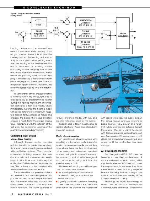
Figure 3. Torque controlled inverter<br />
configuration<br />
loading device can be jammed into<br />
external structures while hoisting. Jamming<br />
causes an immediate stop of the<br />
loading device. Depending on the elasticity<br />
of the ropes and supporting structure,<br />
the loading of the hoisting machinery<br />
is increased by rotating inertia<br />
according to the stopping time of the<br />
machinery. Generally the overload limiter<br />
senses the jamming situation and stopping<br />
is initiated by a hard-wired circuit<br />
which engages the brake and interrupts<br />
the power supply to motor. However, this<br />
is not the fastest way to stop the machinery.<br />
In <strong>Konecranes</strong> drives, snag protection<br />
is initiated when the measured load is<br />
exceeded by a predetermined factor<br />
during the hoisting movement. The initiation<br />
activates a fast stop mode, which<br />
immediately switches the hoisting mode<br />
with speed reference to maximum negative<br />
braking torque reference mode and<br />
engages the brake. The torque direction<br />
change is much faster than brake closing<br />
time. Combined with the initiation of the<br />
fast stop, the occasional loading of the<br />
machinery is reduced significantly.<br />
Combined Multi-Drives<br />
Master-Slave hoisting<br />
Although torque control provides<br />
notable benefits for single drive applications,<br />
even more advantages are realised<br />
with multi-drive systems. Mechanicallyconnected<br />
hoisting systems, like twin<br />
drum or twin motor systems, can easily<br />
begin to vibrate or even tackle against<br />
each other if driven by two separate drives.<br />
This problem can be avoided with<br />
the Master–Slave drive connection.<br />
The master drive has speed and direction<br />
reference as normal and gives as output<br />
the run and actual torque information.<br />
The master drive also controls the<br />
brake and its “slow down” and “stop” limit<br />
switch functions. The slave operates in<br />
18 KONECRANES’ WORLD No 7<br />
torque reference mode, with run and<br />
direction references given by the master.<br />
Special care is taken in abnormal or<br />
tripping situations. If one drive stops, both<br />
drives are stopped.<br />
Master–Slave traversing<br />
An unbalanced situation occurs with<br />
travelling motion when both sides of a<br />
moving crane are unequally loaded. In a<br />
case where there are two synchronised<br />
but separate speed reference- controlled<br />
inverters driving both sides of the crane,<br />
the inverters may start to tackle against<br />
each other while trying to follow the<br />
speed reference path.<br />
Unbalanced loading conditions typically<br />
occur in connection with:<br />
■ the travelling trolley of an overhead<br />
crane with a long span reaches the<br />
end of the span<br />
■ a gantry crane with cantilever travelling<br />
The advanced solution is to drive the<br />
other side of the crane as the master unit<br />
with speed reference. The master outputs<br />
the actual torque and run references.<br />
Brake control, “slow down” and “stop”<br />
limit switch functions are initiated through<br />
the master. The slave unit is controlled<br />
with torque reference according to outputs<br />
from master. If tripping occurs, both<br />
drives are stopped and prevented from<br />
re-start until the obstruction has been<br />
removed.<br />
AC drive response time<br />
The change from DC to AC drives has<br />
been rapid over the past few years. A<br />
common discussion topic among drive<br />
suppliers is whether AC drives can meet<br />
the requirements for response time. From<br />
the operator’s viewpoint, any response<br />
time (or the delay from actuating a controller<br />
to motor motion) exceeding 250 ms<br />
is characterised as a delay.<br />
Analysing the basic technology of<br />
both DC and AC motors shows why there<br />
is a measurable difference. When motor