Continuous monitoring of your electricity networks ... - Chauvin-Arnoux
Continuous monitoring of your electricity networks ... - Chauvin-Arnoux
Continuous monitoring of your electricity networks ... - Chauvin-Arnoux

You also want an ePaper? Increase the reach of your titles
YUMPU automatically turns print PDFs into web optimized ePapers that Google loves.
CONTACT<br />
No. 16 MEASUREMENT • NEWS SPRING 2001<br />
Test & Measurement<br />
LF disturbance and voltage quality<br />
Power<br />
Measurement & Control<br />
<strong>Continuous</strong> <strong>monitoring</strong> <strong>of</strong><br />
<strong>your</strong> <strong>electricity</strong> <strong>networks</strong><br />
Temperature<br />
Measurement & Control<br />
Pt 100 Ω sensors and<br />
insertion pyrometers
CONTENTS<br />
Company news . . . . . . . . . . . . . . . . . . . . . . . . . . . . . .3<br />
Theory<br />
The measurement <strong>of</strong> electrical power . . . . . . . . . . . . . .4<br />
New products<br />
A new wattmeter concept . . . . . . . . . . . . . . . . . . . . . . .6<br />
Selective RF Receiver . . . . . . . . . . . . . . . . . . . . . . . . .12<br />
Testers for <strong>your</strong> physical measurements . . . . . . . . . .14<br />
True RMS Multimeter . . . . . . . . . . . . . . . . . . . . . . . . .17<br />
Two Metrix multimeter clamps . . . . . . . . . . . . . . . . .18<br />
The new range <strong>of</strong> ULYS energy meters . . . . . . . . . . . .22<br />
A measurement station for LV <strong>networks</strong> . . . . . . . . . .23<br />
Thyritop 3 QTM power controller . . . . . . . . . . . . . . . .24<br />
Training<br />
Microwave Training Bench . . . . . . . . . . . . . . . . . . . . .11<br />
Focus<br />
Microwave Wattmeter-Reflectometers . . . . . . . . . . . .13<br />
FFT and harmonic analysis: a major advance . . . . . . .16<br />
Voltage probes for oscilloscopes . . . . . . . . . . . . . . . .18<br />
Pt 100s and insertion pyrometers . . . . . . . . . . . . . . .26<br />
Applications<br />
Power control gets a breath <strong>of</strong> fresh air . . . . . . . . . . .25<br />
Special reports<br />
LF disturbance: voltage quality is something that<br />
can be measured . . . . . . . . . . . . . . . . . . . . . . . . . . . . .7<br />
<strong>Continuous</strong> <strong>monitoring</strong> <strong>of</strong> the quality <strong>of</strong> <strong>your</strong><br />
<strong>electricity</strong> <strong>networks</strong> . . . . . . . . . . . . . . . . . . . . . . . . . .19<br />
Kiosk . . . . . . . . . . . . . . . . . . . . . . . . . . . . . . . . . . . .27<br />
TECHNICAL<br />
INFORMATION JOURNAL<br />
Communication Dept.<br />
190, rue Championnet<br />
75876 PARIS Cedex 18 - FRANCE<br />
Tel: 33 1 44 85 44 85<br />
Fax: 33 1 46 27 73 89<br />
http://www.chauvin-arnoux.com<br />
e-mail: info@chauvin-arnoux.com<br />
Distributed free<br />
all reproduction rights reserved<br />
SPRING 2001<br />
Cover photo:<br />
Electrical Network Measurement Campaign<br />
using analyser C.A 8350<br />
PUBLISHING DIRECTOR<br />
Claude GENTER<br />
MANAGING EDITOR<br />
Anaïde DER AGOBIAN<br />
EDITOR<br />
Olivier LOMBAERDE<br />
CONTRIBUTORS<br />
Didier BISAULT<br />
Jean-Pierre CARITEY<br />
Jean-Yves FABRE<br />
Marie-Aude MASSIN<br />
Rachel OUTRAM<br />
Pascal PERNIN<br />
Didier PIAUD<br />
Thierry VIGNERON<br />
GRAPHIC DESIGN AND LAYOUT<br />
Pastelle Communication<br />
Tel: 33 1 45 45 22 02<br />
For further information, contact <strong>your</strong> local agency,<br />
or our export departments in France<br />
TEST & MEASUREMENT DIVISION<br />
Tel: 33 1 44 85 44 86 - Fax: 33 1 46 27 95 59 - e-mail: export@chauvin-arnoux.fr<br />
POWER MEASUREMENT & CONTROL DIVISION<br />
Tel: 33 1 47 46 78 85 - Fax: 33 1 47 35 01 33 - e-mail: info@enerdis.fr<br />
TEMPERATURE MEASUREMENT & CONTROL DIVISION<br />
Tel: 33 4 72 14 15 52 - Fax: 33 4 72 14 15 41 - e-mail: export@pyro-controle.tm.fr<br />
CHAUVIN ARNOUX UK<br />
Tel: 1 628 78 8 888 - Fax: 1 628 628 099<br />
e-mail: info@chauvin-arnoux.co.uk<br />
To receive sales literature, fill out the Reader Service<br />
form between pages 14 and 15.<br />
EDITORIAL<br />
CHAUVIN ARNOUX<br />
& ITS SUBSIDIARIES<br />
<strong>Chauvin</strong> <strong>Arnoux</strong>, Europe’s largest Electrical Test & Measurement<br />
Equipment Company recently celebrated its 107th birthday.<br />
Unusually, in today’s frantic and ever changing business environment,<br />
<strong>Chauvin</strong> <strong>Arnoux</strong> is still a family owned and managed company. This<br />
independence and continuity has allowed values and operating principles<br />
more associated with smaller companies to be vigorously maintained,<br />
demonstrating an on-going practical commitment to the environment, education<br />
establishments, organisations and the people it serves. Extremely<br />
important issues <strong>of</strong> customer care, product quality and electrical safety<br />
are paramount in the daily activities <strong>of</strong> our company, and essential to our<br />
present and future successes. <strong>Chauvin</strong> <strong>Arnoux</strong> is committed to producing<br />
and developing quality products, suited to the needs <strong>of</strong> their customers,<br />
at a realistic and competitive price.<br />
Our customers are our most important and valuable assets.<br />
We at <strong>Chauvin</strong> <strong>Arnoux</strong> (UK), Maidenhead, Berkshire are one example <strong>of</strong><br />
the many global subsidiaries reporting into France.<br />
Maidenhead is a very busy subsidiary, staffed by friendly, dedicated and<br />
pr<strong>of</strong>essional people, who try their very best to <strong>of</strong>fer our customers a service<br />
<strong>of</strong> excellence. We attempt to emulate those values and operating principals<br />
established and evolved by <strong>Chauvin</strong> <strong>Arnoux</strong> over its 107 year history. We<br />
have a large and varied product stocking policy enabling us to <strong>of</strong>fer fast delivery.<br />
Our customers and products are supported by our own direct external<br />
technical sales force, internal customer care team, calibration and service<br />
facilities based in our <strong>of</strong>fices at Maidenhead. <strong>Chauvin</strong> <strong>Arnoux</strong>'s quality<br />
procedures, product and operating controls conform to the many and<br />
various ISO, EMC, EN and IEC directives, rules and regulations.<br />
Please do not hesitate in contacting us, either by telephone or by email,<br />
or in visiting the <strong>Chauvin</strong> <strong>Arnoux</strong> group’s website at www.chauvin-arnoux.com.<br />
Ken Ballinger<br />
General Manager<br />
<strong>Chauvin</strong> <strong>Arnoux</strong> UK<br />
2 CONTACT CONTACT No. 16
No. 16 CONTACT<br />
COMPANY NEWS<br />
A new Sales Manager<br />
is welcomed<br />
into the fold<br />
Peter Hills is the newly appointed Sales <strong>of</strong>fice Manager <strong>of</strong><br />
<strong>Chauvin</strong> <strong>Arnoux</strong> UK. He joined the group in November 2000 as part<br />
<strong>of</strong> the continuing expansion taking place within the United Kingdom.<br />
Peter is responsible for the day-to-day running <strong>of</strong> our sales <strong>of</strong>fice,<br />
<strong>of</strong> which part <strong>of</strong> his role is to maintain regular contact with the French<br />
parent company.<br />
This means that we all benefit due to his ability to speak some French.<br />
The RO600<br />
takes <strong>of</strong>f<br />
Recently marketed (see Contact No. 15), the<br />
RO600 scalar multimeter wins its spurs by<br />
shining in two invitations to tender from prestigious<br />
institutions:<br />
■ In France, an order for 150 units by the<br />
Gendarmerie<br />
■ In Germany, an order for 51 units from the Air<br />
Force<br />
Ideal for operation in the field as well as in the<br />
laboratory, the RO600 is designed to measure<br />
the adaptation, the insertion loss or the gain <strong>of</strong><br />
a microwave component between 1 MHz and<br />
2.7 GHz. Its “fault location” function, highly<br />
appreciated for the maintenance <strong>of</strong> radio<br />
telecommunication or relay sites, determines with<br />
accuracy where an anomaly is on a coaxial cable<br />
between transmitter/receiver and antenna.<br />
The use <strong>of</strong> scroll menus making the configurations<br />
implicit means that the R0600 is a very<br />
user-friendly instrument.<br />
Its excellent value for money and the remarkable<br />
simplicity <strong>of</strong> the man/machine interface make it<br />
the choice <strong>of</strong> demanding customers, ahead <strong>of</strong><br />
those <strong>of</strong> the competition.<br />
Reader Service No. 1<br />
New director<br />
for the T & M division<br />
Mr. Philippe WEIL, a specialist in Measurement and Industrial Inspection<br />
with twenty years' experience, arrived at the company in June 2000<br />
and was put in charge <strong>of</strong> the Marketing Department <strong>of</strong> the Test &<br />
Measurement Division for the <strong>Chauvin</strong> <strong>Arnoux</strong> group.<br />
He will therefore be responsible for managing products marketed under<br />
the 2 brands (<strong>Chauvin</strong> <strong>Arnoux</strong> and Metrix) and supporting their international<br />
development.<br />
We wish him the best <strong>of</strong> luck in his new mission.<br />
Should<br />
anyone wish<br />
to meet us…<br />
Throughout the first half <strong>of</strong> the year 2001,<br />
we will be taking part in various <strong>of</strong> the main<br />
European pr<strong>of</strong>essional trade fairs and exhibitions;<br />
as shown below.<br />
As many will agree, this is an ideal opportunity<br />
for listening and conversing, for being shown our<br />
latest additions to the <strong>Chauvin</strong> <strong>Arnoux</strong> product<br />
line and also for giving us <strong>your</strong> opinions in person.<br />
13/03 – 15/03 EMV Ausburg - Germany<br />
19/03 – 21/03 Cigré Tripoli - Libya<br />
23/04 – 28/04 Industrie Hanover - Germany<br />
23/05 – 27/05 INTEL Milan - Italy<br />
18/06 – 21/06 CIRED Amsterdam<br />
20/06 – 22/06 ELTEC Nürnberg - Germany<br />
A new<br />
address for<br />
our American<br />
subsidiary<br />
CHAUVIN ARNOUX, INC<br />
d.b.a AEMC Instruments<br />
200 Foxborough Blvd<br />
Foxborough, MA 02035 - USA<br />
Tel: 1 508 698 2115 - Fax: 1 508 698 2118<br />
http://www.aemc.com<br />
ISO 9001 for<br />
AMRA SpA<br />
Since the merger <strong>of</strong> our Italian subsidiary<br />
AMRA–CHAUVIN ARNOUX and MTI, former<br />
subsidiary <strong>of</strong> the ITT Canon group, the activities<br />
<strong>of</strong> the two companies were reorganised and<br />
grouped at the end <strong>of</strong> December 1999 on the<br />
same site, in Macherio near Milan. Independent<br />
since the end <strong>of</strong> the 70s, MTI makes electromagnetic<br />
relays complementary to those made<br />
by AMRA.<br />
Today, the new company site is home to two relay<br />
manufacturing lines. This site was audited by<br />
the certification company DNV, which recognised<br />
its Quality Assurance system as compliant with<br />
the requirements <strong>of</strong> ISO 9001.<br />
This certification applied to production activities as<br />
well as commercial activities selling electrical and<br />
electronic equipment.<br />
AMRA SpA<br />
Via Sant’Ambrogio 23/25<br />
20050 BAREGGIA DI MACHERIO (MI)<br />
Tel.: (039) 245 75 45<br />
Fax: (039) 481 561<br />
e-mail: info@amra-chauvin-arnoux.it<br />
http://www.chauvin-arnoux.it<br />
3
THEORY<br />
Measurement <strong>of</strong> electrical power<br />
Instantaneous, mean, active, reactive and apparent electrical power, power factor, etc.<br />
We would like to remind you about these basic parameters in electronics and about three-phase measurement<br />
methods.<br />
Definition <strong>of</strong> electrical power<br />
At a given moment, when a current i travels from generator G to receiver R<br />
in the direction defined by the voltage v delivered by the generator (figure 1),<br />
the instantaneous power supplied to the receiver R is equal to product v.i.<br />
G V<br />
R<br />
Generator Receiver<br />
If the voltage and current are DC, the mean power V.I is equal to the<br />
instantaneous power v.i.<br />
If the voltage and current are sinusoidal AC,there is generally a phase shift ϕ<br />
between the voltage and the current (figure 2).<br />
The instantaneous values <strong>of</strong> voltage v and current i have the form:<br />
v = Vmax cos ωt<br />
i = Imax cos (ωt - ϕ)<br />
Where ω, the pulse, is proportional to the frequency F (ω = 2πF).<br />
V max<br />
I max<br />
The phase shift ϕ is, conventionally, counted as positive when the current is<br />
delayed in relation to the voltage.<br />
The instantaneous power has a value <strong>of</strong>: Vmax . Imax . cos ω . cos (ωt - ϕ).<br />
You must take the average value <strong>of</strong> this product during a period to obtain<br />
the expression <strong>of</strong> the power provided by generator G to receiver R. This power<br />
is called the active power and is expressed by the formula:<br />
Vmax .Imax<br />
P = cos ϕ = Veff . Ieff . cos ϕ<br />
√2<br />
The wattmeters provide the expression <strong>of</strong> this product, either by causing<br />
a deviation <strong>of</strong> the pointer in the case <strong>of</strong> a device with an electrodynamic<br />
or ferrodynamic moving coil, or by supplying a DC current or a voltage<br />
i<br />
figure 1<br />
figure 2<br />
proportional to the product in the case <strong>of</strong> electronic wattmeters; this current<br />
or this voltage is then applied to an analogue or digital display.<br />
The existence <strong>of</strong> a phase shift ϕ between the current and the voltage leads,<br />
for AC currents, to the introduction <strong>of</strong> 3 additional quantities:<br />
■ The apparent power S = Veff . Ieff, in VA (volt-amperes), defining the voltage<br />
Veff not to be exceeded (insulator breakdown, increase in core loss) and<br />
the intensity Ieff circulating in the receivers.<br />
■ The power factor:<br />
P P<br />
cos ϕ = =<br />
S Veff . Ieff<br />
when the current and voltage are sinusoidal quantities.<br />
■ The reactive power Q = Veff . Ieff . sin ϕ, in rva (reactive volt-amperes).<br />
The latter may be directly measured by a wattmeter if for voltage<br />
Vmax . cos ωt we substitute a phase-shifted voltage <strong>of</strong> π/2, i.e.<br />
Vmax x cos (ωt - π/2).<br />
The mean product measured will be<br />
Vmax . Imax . cos (ωt - π/2) x cos (ωt - ϕ) which is expressed by:<br />
Vmax .Imax<br />
Q = cos (π/2 - ϕ) = Veff . Ieff . sin ϕ<br />
√2<br />
Knowing P and Q, we can calculate the apparent power and the power factor:<br />
Apparent power: S = √P 2 +Q 2<br />
Power factor: PF = P/S = P/√P 2 +Q 2<br />
Knowing the parameters defined above: active power, reactive power, apparent<br />
power, power factor, is fundamental in electrical engineering and enables<br />
accurate calculation <strong>of</strong> the characteristics <strong>of</strong> the equipment used: yield, load,<br />
cos ϕ, utilisation limits. The wattmeters used for these measurements are<br />
classified in three major families: electrodynamic, ferrodynamic and electronic.<br />
Measurement <strong>of</strong> active power<br />
4-wire balanced three-phase measurement (3 phases + neutral)<br />
The intensities circulating in the three phases are equal in terms <strong>of</strong> rms<br />
values I1 = I2 = I3 and show the same phase shift ϕ in relation to the respective<br />
voltages <strong>of</strong> the 3 phases.<br />
If U1N is the simple voltage measured between phase 1 and neutral, power<br />
P1 supplied by phase 1 will be obtained by connecting a wattmeter as shown<br />
in figure 3.<br />
Its value will be: P1 = U1N . I1 .cos ϕ<br />
The total power supplied P will be equal to 3 P1.<br />
4 CONTACT<br />
No. 16
I1<br />
1<br />
I2<br />
2<br />
I3<br />
3<br />
N<br />
U 1 N<br />
No. 16 CONTACT<br />
THEORY<br />
I* I’<br />
P1<br />
U’<br />
U*<br />
Note: The expression P1 = U1N . I1 . cos ϕ in the scalar product <strong>of</strong> the 2 vectors<br />
➝ ➝<br />
U1N and I1 which enables use <strong>of</strong> the notation<br />
➝ ➝<br />
P1 = U1N . I1<br />
and in three-phase:<br />
➝➝ ➝➝ ➝➝<br />
P = U1N . I1 + U2N . I2 + U3N . I3<br />
Measurement in 3-wire balanced three-phase (3 phases no neutral)<br />
The intensities circulating in the three phases are equal I1 = I2 = I3.<br />
An artificial neutral is created using three resistors R, R et R’. The sum<br />
R’ + r must be equal to R (r is the resistance <strong>of</strong> the voltage circuit <strong>of</strong> the unit).<br />
This returns us to the previous case with U1N between phase 1 and<br />
the artificial neutral (figure 4).<br />
1<br />
2<br />
3<br />
I1<br />
I2<br />
I3<br />
U 1N<br />
I*<br />
P1<br />
U*<br />
U'<br />
R’ R R<br />
P1 = Power supplied on phase 1<br />
Totale P supplied = 3 U1N . I1 . cos ϕ = 3P1.<br />
I’<br />
N<br />
USE<br />
USE<br />
figure 3<br />
figure 4<br />
With many wattmeters, the balanced three-phase measurements (3 phases<br />
no neutral) are performed directly; the artificial neutral point recreated by<br />
the resistors R, R and R’ is included in the instrument (astatic wattmeter, CdA<br />
778 wattmeter, for example). This design is shown in the diagram by the<br />
dotted section.<br />
Measurement in 3-wire unbalanced three-phase (3 phases no neutral) -<br />
method using two wattmeters.<br />
Whether the circuit is balanced or not in the absence <strong>of</strong> a neutral, there<br />
remains I1 + I2 + I3 = 0.<br />
In this case, the general expression <strong>of</strong> the power given above is simplified<br />
➝ ➝ ➝ ➝ ➝ ➝<br />
P = (U1N – U3N . I1 + (U2N – U3N). I2<br />
➝ ➝ ➝ ➝<br />
so P = U13 . I1 + U23 . I2<br />
and the measurement <strong>of</strong> the total power may be carried out using two<br />
wattmeters (figure 5).<br />
U13 and U23 are the phase-to-phase voltages measured respectively between<br />
phase 1 and phase 3 and then between phase 2 and phase 3.<br />
I1<br />
1<br />
I2<br />
2<br />
I3<br />
3<br />
I*<br />
Two cases may arise:<br />
P1<br />
U* U’<br />
a) P1 ≥ 0 and P2 ≥ 0, then Ptotal = P1 + P2<br />
b) one wattmeter deviates to the right and the other is as far as it will go to<br />
the left. To read the second; transfer the feed wires to the voltage circuit:<br />
U*.U’ becomes U’.U*.<br />
The value will be considered negative and we will obtain: Ptotal = P1 – P2<br />
If it is a digital wattmeter we will add together the algebraic values displayed.<br />
Note: it is possible to use a single wattmeter successively connected to 2<br />
positions, using an inverter switch. This type <strong>of</strong> switch contains auxiliary<br />
contacts ensuring short-circuiting <strong>of</strong> the unused contacts.<br />
Measurement in 4-wire balanced three-phase (3 phases + neutral)<br />
I1<br />
1<br />
I2<br />
2<br />
I3<br />
3<br />
N<br />
We obtain Ptotal = P1 + P2 + P3 (figure 6).<br />
I’<br />
I* I’<br />
P2 USE<br />
U’<br />
U*<br />
I*<br />
P1<br />
I’<br />
U1N<br />
U* U’<br />
I*<br />
P2<br />
I’<br />
U2N U* U’<br />
I*<br />
P3<br />
I’<br />
U3N<br />
U* U’<br />
USE<br />
figure 5<br />
figure 6<br />
In this case, we must use 3 wattmeters and add the readings together.<br />
If the measurement is stable, we can successively carry out 3 measurements<br />
with a single wattmeter. Caution: it is recommended to use a system<br />
preventing the intensity circuits from being cut <strong>of</strong>f during switching.<br />
5
NEW PRODUCT<br />
A new wattmeter<br />
concept,<br />
the “powermeter”<br />
The wattmeter, at least in its single function version, was long<br />
resistant to digital technology.<br />
Today, it would be unfortunate to be deprived <strong>of</strong> the possibilities<br />
<strong>of</strong> this technology, especially when the improvements made are not<br />
more expensive but cheaper!<br />
Given their large measurement range and their<br />
sensitivity, the METRIX instruments PX 120<br />
and PX 110 are designed for general or technical<br />
secondary schools, installers and industrial<br />
maintenance services. More specifically, their<br />
ability to measure RMS values in AC + DC enables<br />
them to take measurements in all 4 quadrants on<br />
signals disturbed and polluted by harmonics. Both<br />
instruments are suited for field and laboratory<br />
measurements. The only difference between the<br />
two models: the PX 120 measures power in<br />
3-wire balanced three-phase (T3FE) systems, while<br />
the PX 110 is reserved for single-phase systems.<br />
Implementation and robustness<br />
Though providing advanced functions, the PX 120<br />
and PX 110 are very simple to use. Each <strong>of</strong> the<br />
five (PX 110) or six keys (PX 120) corresponds to<br />
a single clearly identifiable function. The function<br />
is directly accessible simply by pressing. Finally, the<br />
automatic range change function frees the user<br />
from adjustments.<br />
The moulded elastomer casing gives<br />
these devices excellent handling characteristics<br />
and outstanding robustness.<br />
For table use, a stand raises the unit to<br />
30°, making it easier to read the results.<br />
This stand can be clipped to the bottom<br />
during on-site measurements.<br />
Inrush currents<br />
and unstable measurements<br />
There are certain loads, such as motors, heating<br />
resistors and lighting systems, which draw large<br />
amounts <strong>of</strong> current when switched on. These<br />
The PX 120 and 110 are compliant with safety standard EN 61010 Ed 99,<br />
Category III, 600 V - Class 2.<br />
currents, although short-lived, may trigger safety<br />
systems or even damage an installation.<br />
The PX 120 and PX 110 are equipped with the<br />
INRUSH function to deal with this problem.<br />
It involves measuring the maximum value <strong>of</strong><br />
the samples during a half-period.<br />
This value is automatically maintained until a new,<br />
higher value is measured.<br />
The SMOOTH function is very useful when<br />
the measurement is unstable. It filters the<br />
measurements using a time constant <strong>of</strong> approximately<br />
3 seconds. The display stability then<br />
changes from 5 counts to 2 counts.<br />
The user can then take full advantage <strong>of</strong> the exceptional<br />
readability <strong>of</strong> these units: a particularly large<br />
digit size (14 mm), a display capacity <strong>of</strong> 9999<br />
counts (4 digits) on three lines, simultaneous<br />
display <strong>of</strong> three values, etc. Only two different<br />
tables are required to display all the quantities<br />
measured by the units.<br />
Communication, the cutting edge!<br />
The word digital also means communications<br />
options! These new wattmeters are also<br />
distinguished by their infrared transmission mode.<br />
The days <strong>of</strong> faulty contacts are past! The link<br />
is established using a magnetised optical head<br />
positioned simply on the front panel <strong>of</strong> the unit.<br />
A s<strong>of</strong>tware processing system displays the<br />
different quantities on a PC screen, prints screens<br />
or transfers measurement files to a spreadsheet<br />
for storage.<br />
Finally, given their possibilities, the PX 120 and<br />
110 are much more than simple wattmeters.<br />
They herald a new concept: that <strong>of</strong> the “powermeters”.<br />
Reader Service No. 2<br />
6 CONTACT<br />
No. 16
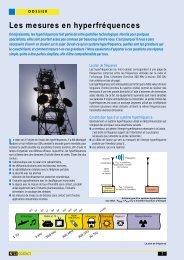
SPECIAL REPORT<br />
LF disturbance: voltage<br />
quality is something<br />
that can be measured<br />
For several years, we have been observing an increase in so-called<br />
"non-linear" loads on <strong>networks</strong> linked to electronic data processing and<br />
power electronics equipment. Now, these loads play a part in deteriorating supply voltage.<br />
They are also detrimental when it comes to operating electrotechnical equipment and material at maximum<br />
capacity. In this report, we will endeavour to set out the main types <strong>of</strong> disturbance encountered, their causes, the<br />
measures to be taken as well as certain clearly defined limits, bearing in mind that the results <strong>of</strong> the measurements<br />
must be recorded over a period <strong>of</strong> at least one week.<br />
For an electric energy distributor, it is <strong>of</strong> paramount importance to deliver<br />
a top-quality product, meaning a balanced three-phase sinusoidal 50 Hz<br />
voltage at a rated value. By doing so, he is being consistent with the invoice<br />
sent out to the user customer.<br />
The relevant standards<br />
In order to help distributors and users in their steps to <strong>monitoring</strong> and<br />
improving the quality <strong>of</strong> <strong>electricity</strong> <strong>networks</strong>, several standards have been<br />
instituted or are in the course <strong>of</strong> being drawn up.<br />
The NF EN 50160 standard was established so as to characterise the quality<br />
<strong>of</strong> the voltage supplied. This standard sets out the various types <strong>of</strong> voltage<br />
disturbance observed at the customer's delivery location, depending on<br />
the waveform, voltage level as well as the frequency and imbalance <strong>of</strong> the<br />
three-phase system. It thus lists the parameters to be monitored and the<br />
length <strong>of</strong> time during which they should be monitored.<br />
The standard which is currently undergoing preparation, IEC/EN 61000-4-30,<br />
defines the measuring methods for each parameter along with the<br />
measuring conditions and procedures.<br />
Two standards, IEC 61000-2-2 for LV <strong>networks</strong> and IEC 61000-2-12 for AV<br />
<strong>networks</strong>, define the so-called acceptable "compatibility" levels for each<br />
parameter.<br />
Slow variations: voltage troughs, overvoltages and outages<br />
The amplitude <strong>of</strong> the voltage is a crucial factor for the quality <strong>of</strong> <strong>electricity</strong>.<br />
It generally constitutes the energy distributor's prime contractual engagement.<br />
Combined with the unknown factors in transmission and distribution<br />
network management (such as power monitor adjustments, dispatching and<br />
automatic protection systems), it is subjected to abnormal variations and<br />
can even collapse to a level bordering on zero. To characterise these events,<br />
two parameters are commonly used: the amplitude and the length <strong>of</strong> time<br />
the variation lasts.<br />
Several types <strong>of</strong> defects are defined: overvoltage, voltage trough and<br />
outage. The nominal variation range for the network voltage is fixed by the<br />
energy distributor, generally speaking at ± 10% <strong>of</strong> the phase-to-phase voltage.<br />
The overvoltages are measured in amplitude and duration when the upper<br />
threshold <strong>of</strong> the nominal range is overshot. The voltage troughs are counted<br />
when the voltage is lower than the lower threshold <strong>of</strong> the nominal range (see<br />
figure 1). Most commonly, these variations last less than 0.2 seconds in AV<br />
and HV. Over a period <strong>of</strong> one year, the number <strong>of</strong> voltage troughs can go from<br />
a few dozen to around a thousand.<br />
In normal conditions, the number <strong>of</strong> very short outages can vary from a few<br />
dozen to several hundred per year and not last longer than 1 second.<br />
No. 16 CONTACT<br />
Voltage amplitude<br />
∆ V<br />
t<br />
10 % <<br />
t > 10 ms<br />
t (ms)<br />
Several types <strong>of</strong> phenomena can be seen to cause the voltage variations.<br />
When they arise at producer level, it is always a question <strong>of</strong> uncertain<br />
phenomena such as lightning or accidental short circuits (defective insulation,<br />
fissure in a cable, branches falling on overhead <strong>electricity</strong> lines, etc.)<br />
which are to blame. At consumer level, it is essentially the installation itself<br />
which is at fault. Therefore, connecting up heavy loads can bring about<br />
variations in voltage if the short-circuit power at a delivery point is <strong>of</strong> too low<br />
capacity. High-power engines, transformers and capacitor assemblies are<br />
the loads which most commonly give rise to voltage variations. The effects<br />
<strong>of</strong> such loads can increase considerably when a large number <strong>of</strong> customers<br />
are connected to the same branch. In the case <strong>of</strong> a rotary engine, the<br />
variations can have a dramatic influence on the engine itself. Therefore,<br />
when a defect appears, all those customers connected at the same level<br />
on the network are affected by the voltage variations.<br />
The major difficulty consists in measuring the duration and amplitude <strong>of</strong><br />
these voltage variations very accurately, especially when the variation in<br />
voltage appears on all the three phases with different durations and<br />
amplitudes. It has become a necessity to use so-called "three-phase" network<br />
analysers in order to analyse the three phases simultaneously.<br />
Rapid variations: transient overvoltages<br />
Those overvoltages lasting less than 10 ms are known as "transient<br />
overvoltages" (figure 2). These overvoltages are caused by atmospheric<br />
phenomena (lightning) or, more frequently, by electrical equipment being<br />
operated (more or less inductive load commutations producing transient<br />
overvoltages at high frequency).<br />
∆ V<br />
V<br />
≤ 100 %<br />
Figure 1: voltage troughs<br />
7
SPECIAL REPORT<br />
These transient phenomena can also arise when two thyristors are commutated,<br />
prompting a very short-lived short circuit between the two phases.<br />
The rise time can vary from less than a few microseconds to several<br />
milliseconds. These LV overvoltages generally remain below 800 V, but they<br />
can go over 1,000 V subsequent to a fuse melting.<br />
Voltage amplitude<br />
Measuring transient overvoltages requires specific analysers using digital<br />
technology and a high sampling frequency.<br />
Triggering a contactor<br />
causes a current peak<br />
to appear, the effect<br />
<strong>of</strong> which is a voltage<br />
drop (on either side<br />
<strong>of</strong> the cursor, shown<br />
here in pink).<br />
Flicker or rapid voltage fluctuations<br />
The discomfort felt by the human optical system when variations <strong>of</strong> light<br />
intensity occur, what we call "flickering", is measured by the value <strong>of</strong> the<br />
flicker. Its main effects on a human being can be headache, irritability and<br />
sometimes even epilepsy.<br />
Voltage amplitude<br />
0<br />
100 µs<br />
3 ms<br />
0 10 20<br />
The flicker is in reality a statistical calculation, defined by the<br />
EN IEC 61000-4-15 standard and obtained from measuring the rapid<br />
variations in voltage. These rapid variations in voltage (figure 3) are, generally<br />
speaking, caused by variable loads such as arc furnaces, laser printers,<br />
micro-wave ovens or air conditioning systems being started up.<br />
The method <strong>of</strong> measurement must be representative <strong>of</strong> the discomfort felt<br />
and take into account the mechanisms <strong>of</strong> vision. To achieve that, the flicker<br />
must be assessed over a sufficiently long period <strong>of</strong> time. Moreover,<br />
due to the uncertain nature <strong>of</strong> the flicker, caused only by certain loads, its<br />
instantaneous level can vary considerably and unpredictably during this<br />
period.<br />
A 10-minute space <strong>of</strong> time has been deemed to be a good compromise for<br />
t (ms)<br />
Figure 2: transient overvoltages<br />
t (ms)<br />
Figure 3: rapid variations in voltage<br />
assessing what is called the short-term flicker, or "Pst". It is long enough to<br />
avoid granting too much importance to isolated voltage variations. It is also<br />
long enough to allow an inexperienced person to notice the disturbance and<br />
its persistence. At the same time, it is short enough to enable a piece <strong>of</strong><br />
disruptive equipment with a long operating cycle to be finely characterised.<br />
The period <strong>of</strong> 10 minutes on which the assessment <strong>of</strong> the short-term flicker<br />
severity has been based is valid for assessing the disturbances caused by<br />
individual sources such as rolling mills, heat pumps or electric household<br />
appliances.<br />
In cases in which the combined effect <strong>of</strong> several disruptive loads operating<br />
in an uncertain manner (e.g. welding units or engines) has to be taken into<br />
account, or when the flicker sources in question are ones with a long or<br />
variable operating cycle (e.g. electric arc furnace), the disturbance thus<br />
created is required to be assessed over a longer period. Measuring is set to<br />
last 2 hours, a duration considered appropriate to the operating cycle <strong>of</strong> the<br />
load or one during which an observer can perceive the long-term flicker. The<br />
long-term flicker, or "Plt",will be calculated from the short-term flicker values.<br />
This is a standard function on certain network analysers.<br />
Measuring the severity<br />
<strong>of</strong> the short- and<br />
long-term flicker<br />
Harmonics and interharmonics<br />
In numerous cases, the current consumed by the loads no longer has a pure<br />
sinusoidal shape. Current distortion implies a voltage distortion which also<br />
depends on the source impedance.<br />
The so-called "harmonic" disturbances are caused by non-linear loads such<br />
as pieces <strong>of</strong> equipment with integrated power electronics (variators, inverters,<br />
static converters, dimmers, welding units, etc.) being introduced onto<br />
the network. More generally, all the materials incorporating rectifiers and<br />
chopping electronics distort the currents and create voltage fluctuations on<br />
the low-voltage distribution network. It is the concentration <strong>of</strong> numerous<br />
harmonics "polluters" which generates a huge amount <strong>of</strong> disturbance on<br />
the network.<br />
Voltage amplitude<br />
0 10 20<br />
What we call harmonic is the superposition on the 50 Hz fundamental wave<br />
<strong>of</strong> other waves which are also sinusoidal but which have frequencies that<br />
are multiples <strong>of</strong> the fundamental (figure 4). In order to measure the "current"<br />
or "voltage" harmonics, we use the Fourier transform making it possible to<br />
break a periodic signal down into a sum <strong>of</strong> sinusoidal signals that are<br />
8 CONTACT<br />
No. 16<br />
t (ms)<br />
Figure 4: harmonics
multiples <strong>of</strong> the fundamental frequency. When the signal has a component<br />
which is superposed onto the fundamental wave (50 Hz) and which is not<br />
a multiple <strong>of</strong> the fundamental (e.g. 175 Hz), we speak <strong>of</strong> interharmonics.<br />
The level <strong>of</strong> the interharmonics is also on the increase due to the development<br />
<strong>of</strong> power converters, speed variators and other similar command control<br />
equipment.<br />
All these harmonics can be added up, with the result being the THD (total<br />
harmonics distortion). The frequency range which corresponds to the study<br />
<strong>of</strong> harmonics is generally between 100 and 2,000 Hz, meaning from order<br />
2 to order 40 harmonic. The maximum levels, order by order, are defined in<br />
the IEC 61000-2-2 standard for LV and the IEC 61000-2-12 standard for AV.<br />
Present-day measuring instruments must be capable <strong>of</strong> performing this<br />
harmonic analysis order by order and also overall, so as to carry out a finely<br />
detailed diagnosis <strong>of</strong> the installation.<br />
The consequences <strong>of</strong> these harmonics can be instantaneous on certain electronic<br />
appliances and instruments: functional disorders (synchronisation,<br />
commutation), ill-timed trip-outs, measurement errors on energy meters, etc.<br />
The additional induced temperature rises can, in the medium term, reduce<br />
the life span <strong>of</strong> rotating machines, capacitors, power transformers and neutral<br />
conductors.<br />
Imbalance<br />
SPECIAL REPORT<br />
Voltage, current and power<br />
harmonics spectrum<br />
Voltage amplitude<br />
An unbalanced three-phase electric receiver or unbalanced single-phase<br />
receivers energized by a balanced three-phase network can lead to voltage<br />
imbalances between phases (figure 5).<br />
These imbalances are due to the circulation <strong>of</strong> unbalanced currents through<br />
the network impedances.<br />
Voltage can be broken down by a method known as "<strong>of</strong> symmetrical, direct,<br />
negative phase sequence or homopolar components".<br />
It is well known that the negative phase sequence component causes cases<br />
<strong>of</strong> spurious braking torque and additional temperature rises in alternating<br />
current rotating machines.<br />
No. 16 CONTACT<br />
1 2<br />
3<br />
0 10 20 30 40 t (ms)<br />
Figure 5: voltage imbalance<br />
The imbalance and its three components are given by the network analyser<br />
<strong>of</strong>fering the Imbalance function.<br />
It is generally agreed that no problem can arise with an imbalance <strong>of</strong> less than<br />
2%.<br />
Visual display <strong>of</strong><br />
the imbalance on the<br />
analyser by means <strong>of</strong><br />
the Fresnel graph<br />
Frequency<br />
Frequency fluctuations are most <strong>of</strong>ten observed on <strong>networks</strong> which are<br />
not interconnected, as is the case with Corsica, or <strong>networks</strong> powered by<br />
generator sets. Under normal operating conditions, the average value <strong>of</strong> the<br />
fundamental frequency should be in the 50 Hz ± 1% range (figure 6).<br />
Voltage amplitude<br />
0<br />
f 1/2 f<br />
t (ms)<br />
Figure 6: frequency fluctuations<br />
Conclusion<br />
Problems <strong>of</strong> voltage troughs and outages are becoming more and more<br />
an everyday topic owing to the high level <strong>of</strong> sensitivity <strong>of</strong> certain pieces <strong>of</strong><br />
equipment to these phenomena. Unfortunately, these problems will persist<br />
despite all the improvements made by the distributor to his <strong>networks</strong>.<br />
In France, the Emerald Contract (Contrat Émeraude - green tariff) is applied<br />
to those industrial customers using the EDF (national <strong>electricity</strong> company -<br />
translator's note) distribution network. It includes a contractual undertaking<br />
with regard to troughs and outages depending on the geographical area, and<br />
a personalised undertaking with regard to harmonics, flicker and imbalance.<br />
Voltage disturbances come from the increasing installation by users <strong>of</strong><br />
so-called "fluctuating" loads.<br />
It should therefore be stressed that the quality <strong>of</strong> electric energy depends not<br />
only on the supplier but also on the end user. Checking the quality <strong>of</strong><br />
the <strong>electricity</strong> supply requires the use <strong>of</strong> effective tools which enable all the<br />
parameters described above to be checked. The new three-phase network<br />
analysers allow a complete analysis <strong>of</strong> the network quality parameters,<br />
a diagnosis and an assessment <strong>of</strong> the problems observed on the network.<br />
9
SPECIAL REPORT<br />
Electrical systems:<br />
the full analysis with the C.A 8350<br />
The new C.A 8350 electrical system quality analyser, is a product <strong>of</strong> development and complies with the latest<br />
standards in the field, in particular EN 50160. It provides access to all measurements for complete analysis: power,<br />
harmonics, flicker, transients etc. The touch-sensitive screen makes it remarkably simple and intuitive to use and<br />
program. The operating s<strong>of</strong>tware, Windows TM , handles data formatting in the form <strong>of</strong> tables or colour graphics and<br />
printing <strong>of</strong> analysis campaign reports.<br />
To supplement the article published on this<br />
product in our previous issue, we present here<br />
the various measurement options for electric and<br />
qualimetric parameters, the theory <strong>of</strong> which we<br />
broached in the 3 previous pages.<br />
Harmonics analysis<br />
FFT representation <strong>of</strong> the voltage and current<br />
Representation <strong>of</strong> harmonics (to 50 th order)<br />
and inter-harmonics<br />
Recognition <strong>of</strong> harmonic current direction (input<br />
or output)<br />
Statistical analysis<br />
Oscilloscope Mode<br />
Wave form display:<br />
4 voltages and 4 currents<br />
Automatic triggering<br />
Phase imbalance measurement<br />
Automatic Scaling<br />
8-trace<br />
Oscilloscope<br />
“Flicker” rate measurement<br />
Graphic time representation<br />
Short-term “flicker” rate<br />
Long-term “flicker” rate<br />
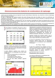
Energy and power <strong>monitoring</strong><br />
Representation <strong>of</strong> voltage, current, power and<br />
energy values in the form <strong>of</strong> tables Monitoring<br />
<strong>of</strong> mini, maxi and average values<br />
Display <strong>of</strong> power pr<strong>of</strong>iles<br />
Power<br />
and energy<br />
analysis<br />
Vector representation<br />
Voltage, currents and harmonics<br />
Automatic Scaling<br />
Verification <strong>of</strong> connection and phase rotation<br />
Summary <strong>of</strong> different measurements on each<br />
phase<br />
Voltage Monitoring<br />
Representation <strong>of</strong> voltage fluctuations with ratio<br />
<strong>of</strong> non-standard values<br />
Monitoring according to standard EN 50160<br />
Statistical analysis and sorting<br />
Voltage<br />
fluctuation<br />
analysis<br />
Summary<br />
table<br />
EN 50160<br />
Recording <strong>of</strong> transients<br />
Monitoring - Trigger selection<br />
Pre/post triggering<br />
Summary event table<br />
Time and date stamping and event duration<br />
Data recorder<br />
Analogue and digital inputs<br />
Meter inputs<br />
Connection on USB port <strong>of</strong> C.A 8350<br />
Recording<br />
<strong>of</strong> transient<br />
thresholds<br />
(40 µs in<br />
single phase)<br />
PC s<strong>of</strong>tware<br />
The s<strong>of</strong>tware, delivered as standard with the<br />
C.A 8350, can be used to analyse data, make a<br />
diagnosis and generate and print out clear,<br />
detailed data reports in the selected language<br />
very simply.<br />
Processing <strong>of</strong> data<br />
Printing <strong>of</strong> reports<br />
Printing <strong>of</strong> graphs and tables<br />
Export <strong>of</strong> data to spreadsheet<br />
A4 printing <strong>of</strong> data reports analysed on<br />
selected time windows<br />
An instrument with many advantages<br />
Remarkably intuitive in its use, all the programming<br />
and reading <strong>of</strong> the C.A 8350 is carried out<br />
by pressing its touch-sensitive screen, in a particularly<br />
user-friendly Windows TM environment. With<br />
a memory <strong>of</strong> 6 Gb, long measurement campaigns<br />
are possible. All the parameters can be displayed<br />
instantaneously and simultaneously.<br />
In its basic version, the unit possesses FFT<br />
analysis functions and the oscilloscope mode for<br />
curve display. Then, each user customises his<br />
unit by adding the option(s) he needs: power<br />
analysis and “vectorscope” mode, flicker and<br />
EN 50160 standard analysis, transient recording<br />
and data recording. All these functions are<br />
available simultaneously to facilitate operation.<br />
Reader Service No. 3<br />
10 CONTACT<br />
No. 16
No. 16 CONTACT<br />
TRAINING<br />
Microwave<br />
training bench<br />
8.5 to 9.6 GHz<br />
To meet the requirements <strong>of</strong> teaching and adult training in<br />
both civilian and military contexts, the ORITEL BDH R100<br />
bench can be used for many basic experiments using<br />
microwaves.<br />
This training bench uses the “rectangular<br />
wave guide” technique as per standard<br />
R100/WR90. It covers a frequency range <strong>of</strong><br />
8.5 to 9.6 GHz. This frequency range, with a<br />
wavelength <strong>of</strong> 3 cm, was chosen because <strong>of</strong> the<br />
important developments observed therein and<br />
also for the small dimensions <strong>of</strong> the components.<br />
The ORITEL BDH R100 bench consists <strong>of</strong> a robust<br />
set <strong>of</strong> components and shows great ease <strong>of</strong> use<br />
because <strong>of</strong> the ingenious EASYFIX assembly<br />
ORITEL LAF 100 test track<br />
is fitted, like each component,<br />
with the EASYFIX fast attachment system.<br />
system (<strong>Chauvin</strong> <strong>Arnoux</strong> registered trade mark).<br />
Each component is fitted with the EASYFIX fast<br />
attachment system: 1/4 turn knob and failsafe<br />
system. In a few minutes, the wave guide<br />
configuration required for experimentation is<br />
assembled; the three supports screw on under<br />
the guide and the assembly slides under the ruler.<br />
Basic bench composition:<br />
The bench consists <strong>of</strong> 11 microwave components<br />
and 3 guide supports, with the operating manual<br />
and detailed practical exercises for each experiment,<br />
all included in a carrying case.<br />
Components:<br />
■ Gunn diode oscillator,<br />
■ ferrite isolator,<br />
■ Pin diode modulator,<br />
■ variable attenuator,<br />
■ curve-type wavemeter,<br />
■ measurement line,<br />
■ impedance adapter<br />
■ guide-coaxial transition,<br />
■ coaxial sensor,<br />
■ adapted load,<br />
■ short-circuit<br />
Other components are available optionally:<br />
star coupler, hoghorn antenna etc.<br />
The related measuring instruments (SWR indicator,<br />
Gunn power supply, microwave milliwattmeter,<br />
oscilloscope, etc.) are delivered as options.<br />
Experiments<br />
The main basic microwave experiments, which<br />
can be conducted using this training bench, are:<br />
■ Gunn oscillator analysis<br />
■ wavelength measurement<br />
■ standing wave ratio measurement<br />
■ impedance measurement<br />
■ frequency measurement<br />
■ reading <strong>of</strong> the quadratic law <strong>of</strong> a detector<br />
Teaching aids and detailed practical exercises<br />
complete the operating manual.<br />
Reader Service No. 4<br />
11
NEW PRODUCT<br />
Electric field<br />
mapping within<br />
arm's reach<br />
In order to determine a transmitter's geographical coverage,<br />
so as to estimate the range <strong>of</strong> communications, the electric field<br />
around this transmitter needs to be mapped. The C.A 47 receiver,<br />
combined with an odometer and a GPS, meets this requirement.<br />
In addition to its aptitude for performing selective frequency<br />
measurements, it has a very high level <strong>of</strong> sensitivity and a very<br />
wide dynamic measuring range (between -10 and -130 dBm). Portable instrument designed for the field, the C.A 47 selective<br />
RF receiver has an autonomy <strong>of</strong> a minimum <strong>of</strong> 3 hours.<br />
The C.A 47 measures the electric field picked<br />
up by an antenna, at a determined frequency<br />
between 25 MHz and 2.5 GHz, and over a very<br />
wide dynamic measuring range <strong>of</strong> between<br />
-10 dBm (100 µW) and -130 dBm (0.1 fW).<br />
On principle, this type <strong>of</strong> selective receiver carries<br />
out the measurement at a determined frequency<br />
without being disturbed by the electric fields which<br />
are present on other frequencies. Indeed, it has a<br />
selectivity that can be configured between 1 kHz<br />
and 1 MHz (5 analysis filters: 1 kHz, 8.5 kHz,<br />
16 kHz, 120 kHz, 1 MHz) and can be used over<br />
its whole frequency range (25 MHz to 2.5 GHz).<br />
This technique known as the "measuring window"<br />
(this window can be moved within the frequency<br />
range) is the technique used in spectral analysis.<br />
The following can also be configured: the measuring<br />
rate (between 0.1 and 165 measurements<br />
per second); the choice <strong>of</strong> peak, quasi-peak or<br />
average detection mode; the amplitude (AM) or<br />
frequency (FM) demodulation which can be heard<br />
on the built-in loudspeaker*.<br />
*WARNING! In France, under article R.226 <strong>of</strong><br />
the Penal Code, this demodulation option can only<br />
be used after authorisation has been granted by<br />
the Ministry <strong>of</strong> Defence.<br />
Evolution <strong>of</strong> the electric field in relation to<br />
the distance, at a determined frequency.<br />
Measurements carried out in a vehicle with the<br />
odometer accessory and the LOG 47 s<strong>of</strong>tware.<br />
Its large backlit liquid crystal display (LCD) indicates<br />
all the configuration parameters as well as,<br />
at the same time, the value measured and the<br />
dBm or dBmV unit. The possible configurations<br />
are clearly indicated in the form <strong>of</strong> menus and in<br />
the language <strong>of</strong> the selected messages (English,<br />
French, German, Spanish or Italian).<br />
The configuration parameters can be adjusted by<br />
means <strong>of</strong> a rotary control knob and a numeric<br />
keypad, or via a RS 232 link.<br />
Monitoring function with LOG 47 s<strong>of</strong>tware.<br />
Observing changes to the levels picked up on a<br />
frequency range according to time.<br />
The C.A 47 selective receiver has an internal<br />
memory which can store 5 configuration registers<br />
and 96,000 measurements as well as a RS 232<br />
interface for programming and editing results.<br />
Its LOG 47 systems s<strong>of</strong>tware, available as an<br />
optional extra, enables the measurements to be<br />
processed and archived onto a microcomputer<br />
with a choice from among five languages for<br />
reading the messages.<br />
Designed to be used in the field, this receiver has<br />
an autonomy <strong>of</strong> more than 3 hours and can be<br />
powered at 12 V (from the socket <strong>of</strong> a cigar lighter<br />
in a car) or with a 230 V mains network (115 V<br />
as an optional extra).<br />
Mapping applications<br />
In these applications, the C.A 47, combined with<br />
a microcomputer which is in turn equipped with<br />
the LOG 47 s<strong>of</strong>tware, is taken on board a vehicle.<br />
Two accessories are required in this case: an<br />
odometer and a GPS.<br />
The odometer, fitted to one <strong>of</strong> the wheels <strong>of</strong> the<br />
vehicle, controls the setting <strong>of</strong> the length <strong>of</strong> time<br />
between two measurements proportionally to the<br />
speed <strong>of</strong> the vehicle.<br />
As for the GPS (Global Positioning System), this<br />
positions the signal received into geographical<br />
coordinates, i.e. according to latitude, longitude<br />
and altitude.<br />
Radiocommunications operators use mapping s<strong>of</strong>tware<br />
so as to be able to simulate network coverage.<br />
The C.A 47, equipped with its accessories,<br />
enables the gaps in the advance data to be filled<br />
in by incorporating the field level values observed<br />
and recorded in the field. The map thus drawn<br />
gives the geographical area actually covered<br />
around a transmitter as well as its different ranges.<br />
Example <strong>of</strong> an electric field map plotted by<br />
means <strong>of</strong> specialised s<strong>of</strong>tware, based on<br />
readings from the C.A 47. The measurements<br />
were carried out in a vehicle using the GPS and<br />
odometer accessories which come<br />
with the LOG 47 s<strong>of</strong>tware.<br />
Reader Service No. 5<br />
12 CONTACT<br />
No. 16
On the transmission assembly (transmitter,<br />
wiring and antenna), these wattmeters are<br />
used to verify that the installation meets expected<br />
performance.<br />
Implementation requires no special technical knowhow.<br />
Measurements are carried out directly by the<br />
assembly team who set up the installation. For<br />
maintenance during system operation, the same<br />
applies and the measurements are simple and<br />
quick.<br />
The parameters measured are the incident and<br />
reflected powers <strong>of</strong> up to 1 kW between 2 MHz<br />
and 2.7 GHz, depending on the model. Each wattmeter<br />
in the series operates in a wide bandwidth<br />
(see table) and requires no special accessories<br />
to do so.<br />
No. 16 CONTACT<br />
FOCUS<br />
Microwave wattmeterreflectometers<br />
The ORITEL RW series <strong>of</strong> wattmeters for civilian and military applications is<br />
designed for efficiency: its aim is to verify microwave transmission/reception<br />
installations simply and rapidly without investing in sophisticated and costly<br />
equipment.<br />
For SSB transmissions from 2 to 30 MHz:<br />
the ORITEL RW 511 wattmeter<br />
With their small size and portable carrying bags,<br />
these mulitmeters were designed mainly for use in<br />
the field. Their metal casings are especially robust.<br />
They are also perfectly suited to use in the laboratory.<br />
Two models are referenced by NATO:<br />
■ RW 306, part number 6625-14-472-7790,<br />
■ RW 521, part number 6625-14-441-7702,<br />
Measurement principle<br />
The measurement method involves setting up the<br />
wattmeter-reflectometer in series – between the<br />
output <strong>of</strong> the transmitter and its operating circuit<br />
(cable, antenna). These test units are fitted with<br />
“N female” input and output connectors.<br />
The main component is a wide band bi-directional<br />
coupler which samples and detects simultaneously<br />
a fraction <strong>of</strong> the incident power and a fraction <strong>of</strong><br />
the reflected power.<br />
Military Special<br />
The ORITEL RW 306 wattmeter<br />
is rainpro<strong>of</strong>, robust and<br />
takes up little space. It can<br />
be fitted to any vehicle, using<br />
the powerful magnet on the<br />
back <strong>of</strong> the unit.<br />
NATO part number:<br />
6625-14-472-7790.<br />
The voltage provided by the detectors on the<br />
bi-coupler branches (voltage proportional to the<br />
detected power) is used after amplification to<br />
provide the power measured on a galvanometer<br />
graduated in watts or in dBm (see table).<br />
Model Frequency Power Utilisation<br />
Reader Service No. 6<br />
ORITEL RW 511 2 at 30 MHz 3 W to 1 kW transmission SSB (Single Side Band)<br />
ORITEL RW 306 26 at 90 MHz 100 mW to 100 W frequency-hopping transmitter-receivers<br />
ORITEL RW 5012 25 at 500 MHz 100 mW to 300 W police, DDE, DDSIS <strong>networks</strong><br />
ORITEL RW 501 25 at 1 300 MHz 100 mW to 300 W radio FM, TV <strong>networks</strong><br />
ORITEL RW TDI 800 at 1 300 MHz 30 W to 1 kW (1) TACAN, DME, IFF transmission<br />
ORITEL RW 521 1 300 at 2 700 MHz 3 mW to 10 W (2) Rural UHF <strong>networks</strong><br />
(1): wattmeter graduation in dBm, from +45 to +60 dBm. (2): wattmeter graduation in dBm, from +5 to +40 dBm<br />
For FM and TV <strong>networks</strong> from 25 to 1300 MHz:<br />
the ORITEL RW 501 wattmeter<br />
13
NEW PRODUCT<br />
PHYSICS Line:<br />
<strong>your</strong> testers for<br />
physical measurements<br />
Nine testers for easy measurement <strong>of</strong> temperature, relative<br />
humidity and lighting.<br />
The entire range was designed in a new, light ergonomic casing,<br />
fitted with an anti- shock sheath for greater robustness.<br />
C.A 870 and C.A 872<br />
infrared thermometers<br />
Using these two thermometers, there is no risk<br />
<strong>of</strong> touching a hot surface because the infrared<br />
measurements are made remotely, from -50 to<br />
+260°C.<br />
The C.A 872 is also fitted with a laser sighting<br />
system to aim at the hot spots more accurately.<br />
Characteristics:<br />
■ 2000-count digital display<br />
■ resolution 1°C<br />
■ accuracy ±2% reading or 3°C<br />
■ response time 1 s<br />
■ fixed emissivity 0.95<br />
■ aiming field 10/1<br />
They are fitted with functions for Auto-Hold, backlighting<br />
<strong>of</strong> the display and display in °C or °F.<br />
Infrared measurement principle<br />
All objets whose temperature is higher than absolute<br />
zero (-273.15°C) emit infrared energy. This energy<br />
radiates in all directions at the speed <strong>of</strong> light.<br />
When the C.A 870 is aimed at an object, its lens<br />
captures this energy and focuses it on an infrared<br />
sensor. This detector reacts by generating a voltage<br />
proportional to the amount <strong>of</strong> energy received,<br />
which means that it is proportional to the object’s<br />
temperature.<br />
Certain objects not only emit infrared energy but<br />
also reflect it. Unlike matt surfaces, shiny or highlypolished<br />
surfaces tend to reflect energy. This<br />
reflection is represented by a factor called the<br />
emissivity coefficient which may vary from 0.1<br />
for a highly reflective object to 1 for a theoretical<br />
“black body”.<br />
For the C.A 870 thermometer, the emissivity<br />
coefficient is pre-set to 0.95. This corresponds to<br />
the most common value which covers more than<br />
90% <strong>of</strong> applications.<br />
Infrared distance to target<br />
Infrared<br />
Thermometer<br />
14 CONTACT<br />
No. 16<br />
dia. 5<br />
Diameter <strong>of</strong> measurement field<br />
dia. 5<br />
Temperature measurement with no contact<br />
using C.A 874 infrared probe<br />
The diameter <strong>of</strong> the targeted area depends on its<br />
distance. The closer the target, the smaller the area<br />
and the better the measurement. This “target<br />
distance/targeted area diameter” ratio is also called<br />
the measurement field.<br />
dia. 10<br />
dia. 15<br />
dia. 20 cm<br />
0 0,5 1 1,5 2 m<br />
Distance from target<br />
C.A 874 infrared probe<br />
This infrared temperature probe can adapt to any multimeter with an input<br />
impedance <strong>of</strong> 10 MΩ.<br />
It provides 10 mV per °C, output on standard banana plugs via its<br />
extension cord.<br />
Its measurement range, -20 to +260°C, and its technical characteristics are<br />
identical to the C.A 870 thermometer.<br />
It is equipped with a battery indicator and an Auto-Hold function.<br />
The infrared C.A 874 temperature probe adapts to any multimeter.
No. 16 CONTACT<br />
NEW PRODUCT<br />
K type couple thermometers<br />
C.A 861 - single K type couple input<br />
C.A 863 - dual K type couple input<br />
Two K type couple thermometers with 2000-count<br />
digital display and backlighting. Many K type<br />
couple sensors are available for measurements<br />
from -40 to +1350°C using the C.A 861 and from<br />
-50 to +1300°C using the C.A 863, with ∆T<br />
difference measurement on the latter. They are<br />
equipped with Max., Hold and °C or °F display<br />
functions.<br />
Characteristics:<br />
■ resolution 1°C or 0.1°C<br />
■ response time 400 ms<br />
■ accuracy ±0.1% reading ±1°C for the<br />
C.A 861 and ±0.3% reading ±1°C for the<br />
C.A 863<br />
The C.A 863 is delivered with 2 flexible K couple sensors<br />
and the C.A 861 is delivered with one sensor.<br />
C.A 865 Thermometer with Pt100 probe<br />
This thermometer with a platinum probe <strong>of</strong>fers<br />
excellent accuracy over a measurement range <strong>of</strong><br />
-50 to +200°C.<br />
Its 2000-count digital display is equipped with<br />
backlighting.<br />
Many Pt 100 sensors for special uses are<br />
available optionally. It is equipped with Max.,<br />
Hold and display in °C or °F functions.<br />
Characteristics:<br />
■ accuracy ±0.5°C<br />
■ resolution 0.1°C<br />
■ response time 400 ms<br />
The C.A 865 is delivered with a general-purpose Pt 100 sensor.<br />
C.A 846 thermo-hygrometer<br />
Perfectly suited to environmental measurements,<br />
this thermo-hygrometer gives the temperature and<br />
percentage <strong>of</strong> humidity in the air: -20 to +60°C and<br />
0 to 95% RH.<br />
It is fitted with a Pt 1000 Ω temperature sensor<br />
at 0°C and its humidity sensor is a fast-reaction<br />
capacitive sensor. It is equipped with Max, Hold<br />
and °C or °F display functions.<br />
Its 2000-count digital display has backlighting.<br />
Characteristics:<br />
■ resolution 0.1°C and 0.1% RH<br />
■ temperature accuracy ±0.5°C from<br />
0 to +60°C and ±1°C from -20 to 0°C<br />
■ accuracy for relative humidity ±2.5% from<br />
10 to 90% RH and ±5% from 0 to 10 and 90<br />
to 100% RH<br />
C.A 811 and C.A 813 light meters<br />
Two digital light meters for light measurements with<br />
a silicon photodiode sensor. Measuring range: from<br />
20 to 20 klx for the C.A 811 and 20 to 200 klx for<br />
the C.A 813. The sensor is capable <strong>of</strong> spectral<br />
correction and incidence correction.<br />
They are fitted with the Auto-hold function, max.<br />
value for the C.A 811 and peak value for the<br />
C.A 813.<br />
Their 2000-count digital display is backlit with a function<br />
for display in lx (lux) or in fc (foot-candle).<br />
Characteristics:<br />
■ resolution 0.01 lx<br />
■ accuracy ±3% reading ±10 counts<br />
Sensor with protective cover and extension cord<br />
to facilitate measurement.<br />
Reader Service No. 7<br />
15
FOCUS<br />
FFT and harmonic<br />
analysis:<br />
a major advance!<br />
It is clear that with digital technology, the number <strong>of</strong> functions potentially<br />
available in instruments is exploding. It even makes you wonder sometimes whether these functions serve any<br />
real purpose. In general, the answer is yes! In-depth analysis <strong>of</strong> customer applications and habits indicates new<br />
requirements. This is exactly what has happened with oscilloscopes, with the FFT and harmonic analysis functions<br />
we propose.<br />
In harmonics mode, the cursor automatically<br />
jumps from one overtone to the next, indicating<br />
the number <strong>of</strong> the overtone, its amplitude as a<br />
percentage <strong>of</strong> the fundamental and its<br />
frequency. This representation <strong>of</strong> the harmonics<br />
is richer than a conventional bar display. In<br />
particular, it even works on MLI-type signals.<br />
In FFT mode, the cursor follows all the signal<br />
points, each time indicating the amplitude (in<br />
Volts or dB) and the frequency.<br />
The oscilloscope is an outstanding display tool.<br />
As such, it may be considered the perfect<br />
quality control tool. With digital technology, it has<br />
become possible to progress even more. The<br />
various possibilities for acquisition as well as<br />
measurement enable the oscilloscope to be used<br />
not only for verification, but also as a genuine<br />
diagnostic or survey tool. In other words, the<br />
user first qualitatively checks the operation <strong>of</strong> the<br />
installation or system by displaying its signal and<br />
can then determine the cause <strong>of</strong> the malfunction<br />
or anomaly using measurement tools, all with the<br />
same instrument. Among these tools, advanced<br />
functions have appeared, such as harmonic<br />
analysis or FFT (Fast Fourier Transform).<br />
The reason for this choice?<br />
For harmonic analysis, the answer is simple. The<br />
pollution <strong>of</strong> <strong>networks</strong> and the problems this causes<br />
for the operation <strong>of</strong> an electrical installation and<br />
the devices connected to it represent a highly<br />
topical subject (see page 7). Before carrying<br />
exhaustive, precise analysis using dedicated<br />
instruments, it is useful to quickly and simply<br />
assess the source <strong>of</strong> the pollution and the characteristics<br />
<strong>of</strong> the incriminated equipment.<br />
The oscilloscope, a standard tool, can do this.<br />
The second, FFT, involves analysing complex<br />
signals or checking noise levels. Using this<br />
function, it is possible to assess a noise level or<br />
determine clearly the frequency components <strong>of</strong> a<br />
given signal. Furthermore, this function has a very<br />
interesting educational aspect since it becomes<br />
possible to display on the same screen the form<br />
<strong>of</strong> a characteristic signal and its breakdown into<br />
Fourier series.<br />
Of course, a more accurate measurement may<br />
require the use <strong>of</strong> a dedicated instrument such<br />
as a spectrum analyser, but the cost <strong>of</strong> such an<br />
instrument is not always justified! In the end, isn't<br />
the oscilloscope confirming in its maturity that it<br />
remains the universal instrument par excellence?<br />
Metrix proposes Harmonic Analysis functions and FFT on several <strong>of</strong> its oscilloscopes:<br />
Reader Service No. 8<br />
OX 8100 OX 8050 OX 8062 OX 8042<br />
Operation<br />
Digital and<br />
Analogue<br />
Digital and<br />
Analogue<br />
Digital and<br />
Analogue<br />
Digital and<br />
Analogue<br />
Input Type Conventional Conventional<br />
Differential<br />
CAT II - 600 V<br />
Differential<br />
CAT II - 600 V<br />
Digital bandwidth 100 MHz 60 MHz 60 MHz 40 MHz<br />
Vertical Amplitude<br />
Sampling frequency:<br />
2 mV to 5 V/div. 5 mV to 20 V/div. 10 mV to 200 V/div. 10 mV to 200 V/div.<br />
Single sweep 100 Msam/sec 100 Msam/sec 100 Msam/sec 100 Msam/sec<br />
ETS 20 Gsam/sec 20 Gsam/sec 20 Gsam/sec 20 Gsam/sec<br />
Signal Analysis Function<br />
FFT and standard harmonics analysis<br />
Dynamic 50 dB, linear or logarithmic scales (volts or dB)<br />
Hamming, Hanning, Blackman, or Rectangle windowing<br />
Cursor Amplitude/Frequency slave to the curve<br />
16 CONTACT<br />
No. 16
The latest product in the MX Concept line,<br />
the MX 26 is a 5000-count multimeter at<br />
home in the field, but also in the lab.<br />
In the field…<br />
Users will appreciate its measurement capabilities,<br />
and its ability to measure voltages and currents<br />
even with interference. Because the MX 26 is not<br />
only an RMS AC+DC unit (see box) but also has<br />
a 100-kHz bandwidth which enables it to take<br />
harmonics into account. Furthermore, its “V low Z”<br />
function (low impedance) avoids measuring<br />
spurious voltages, <strong>of</strong>ten a cause <strong>of</strong> error, and its<br />
“Peak” function traps 1 ms positive or negative<br />
interference.<br />
Its display characteristics are also an advantage<br />
for field work: the backlighting facilitates readings<br />
in conditions where there is little light and the<br />
bargraph instantaneously indicates trends.<br />
Finally, it benefits from the compact, robust casing<br />
which characterizes the line and is responsible for<br />
its success with, in particular, easy access to the<br />
batteries and even safer fuses.<br />
No. 16 CONTACT<br />
NEW PRODUCT<br />
Measure and process<br />
<strong>your</strong> signals regardless<br />
<strong>of</strong> their form<br />
METRIX is completing its range <strong>of</strong> MX Concept multimeters with a True<br />
RMS 100 kHz unit, fitted with an infrared digital link.<br />
In the lab…<br />
Its communications capabilities will delight users.<br />
Because <strong>of</strong> its infrared digital output, the MX 26<br />
can be connected directly to a computer. The user<br />
can then acquire data, record it and display it<br />
in graphical form using advanced s<strong>of</strong>tware<br />
(SX-DMMC).<br />
Later, the user will even be able to calibrate<br />
the unit without opening it and print a record <strong>of</strong><br />
the corrections made to the unit using special<br />
s<strong>of</strong>tware.<br />
Its multifunction Elastomer sheath is useful in any<br />
environment: on site, it is used to attach the<br />
probes; on a table, its stand keeps the unit in an<br />
inclined position.<br />
Reader Service No. 9<br />
TECHNICAL CHARACTERISTICS MX 26<br />
Voltage DC 0.5 - 5 - 50 - 500 - 1000 V<br />
Voltage AC 0.5 - 5 - 50 - 500 - 750 V<br />
Current DC 500 mA / 10 A<br />
Current AC 500 mA / 10 A<br />
Other measurements Ω, continuity, diode test, capacity, Frequency<br />
Display 5,000-count / Bargraph / Backlighting<br />
Functions MIN/MAX, AVG, MEM, AUTO MEM, PEAK<br />
IEC 61010 safety CAT III - 600 V - Pol.2<br />
Choose the right instrument for the type <strong>of</strong> signal<br />
to be measured:<br />
Sinusoidal signal with no<br />
DC component<br />
Distorted AC signals with no<br />
DC component<br />
Distorted AC signals with<br />
DC component<br />
Correct<br />
Default<br />
error<br />
capable <strong>of</strong><br />
reaching<br />
30 to 50%<br />
Default<br />
error<br />
capable <strong>of</strong><br />
reaching<br />
30 to 50%<br />
UAVG MultimeterR x 1,1<br />
RMS<br />
Multimeter (AC)<br />
Correct<br />
Correct<br />
Default<br />
error<br />
(depending<br />
on the UDC<br />
value)<br />
* RMS multimeters (AC+DC), are also called TRMS (True RMS) units.<br />
RMS<br />
Multimeter (AC+DC) *<br />
Correct<br />
Correct<br />
Correct<br />
17
FOCUS<br />
4 voltage probes from<br />
150 to 450 MHz<br />
for oscilloscopes<br />
With its new generation <strong>of</strong> HX voltage probes,<br />
METRIX is launching a family <strong>of</strong> advanced,<br />
uniform accessories with an unequalled level<br />
<strong>of</strong> safety. Its design, common to the entire line,<br />
is ergonomically thought out: a guard positions<br />
the fingers naturally and the sleeve, whose colour<br />
changes depending on the model, is retractable,<br />
which facilitates direct grounding connection<br />
<strong>of</strong> the accessories. Identified by full markings,<br />
each model is factory-adjusted for HF compensation;<br />
no need for a screwdriver to perform LF<br />
compensation.<br />
NEW PRODUCT<br />
The new clamp-on multimeters, MX 655<br />
and MX 650, are distinguished by their<br />
technology. The first is a Hall-effect clamp which<br />
can measure AC and DC currents. Also, it features<br />
an RMS converter for AC currents and voltages.<br />
The MX 650 uses the principle <strong>of</strong> measurement<br />
by transformer so it is intended for measurement<br />
<strong>of</strong> AC currents only.<br />
Both are particularly ergonomic; they feature<br />
excellent handling and their displays are large and<br />
clear. A 42-segment bargraph instantly shows all<br />
The series features<br />
fixed filter ratios <strong>of</strong><br />
10:1 to 100:1 and<br />
covers the frequencies<br />
150 MHz to 450 MHz,<br />
with voltages <strong>of</strong> up to 5 kV. With this level <strong>of</strong><br />
performance, these four models are the perfect<br />
answer to industrial needs, as emphasised by<br />
connection accessories such as “hook-type” and<br />
“crocodile clip” probes.<br />
In terms <strong>of</strong> safety, all models are compliant with<br />
standard EN 61010-2-31.<br />
When aesthetics rhymes with<br />
measurement!<br />
signal variations, complementing the 4000-count<br />
display. The units symbol and a battery level<br />
indicator are also included.<br />
Complementary functions<br />
The MX 655 and 650 are fitted with a HOLD<br />
key to freeze the display and facilitate reading,<br />
regardless <strong>of</strong> access or light conditions. There is<br />
a also “Peak” function, capable <strong>of</strong> capturing<br />
1 ms signals, a “Min Max” function, and a “Rel”<br />
Three <strong>of</strong> them even qualify for Category III - 600 V/<br />
Category II - 1000 V.<br />
So get the best out <strong>of</strong> <strong>your</strong> oscilloscopes with<br />
the new METRIX voltage probes!<br />
Combining the functions <strong>of</strong> an AC/DC multimeter and ammeter clamp, the METRIX MX 655 and 650 feature<br />
the essential functions that every electrician needs. As such, for high currents and voltages<br />
(up to 1000 A and 750 VAC / 1000 VDC), they complement the MX 355 and 350.<br />
function for relative measurements. This feature<br />
will be particularly appreciated for compensating<br />
cable resistance.<br />
Another <strong>of</strong> their advantages is their price,<br />
particularly since it includes the measuring leads,<br />
the batteries and a carrying bag well as the clamp.<br />
Reader Service No. 10<br />
TECHNICAL SPECIFICATIONS MX 655 MX 650<br />
AC current<br />
0.05 to 1000 A RMS<br />
(3 calibres)<br />
0.05 to 1000 A<br />
(3 calibres)<br />
DC current 0.1 to 1000 A (3 calibres) -<br />
AC Voltage<br />
0.5 to 750 V RMS<br />
(2 calibres)<br />
0.5 to 750 V<br />
(2 calibres)<br />
DC Voltage<br />
0.2 to 1000 V<br />
(2 calibres)<br />
0.2 to 1000 V<br />
(2 calibres)<br />
Resistance<br />
0.2 Ω to 4 kΩ<br />
(2 calibres)<br />
0.2 Ω to 4 kΩ<br />
(2 calibres)<br />
Frequency (current)<br />
20 Hz to 10 kHz<br />
(2 calibres)<br />
20 Hz to 10 kHz<br />
(2 calibres)<br />
Frequency (Voltage)<br />
10 Hz to 10 kHz<br />
(2 calibres)<br />
10 Hz to 10 kHz<br />
(2 calibres)<br />
Diode test and sound continuity Yes Yes<br />
Clamping dia. 40 mm 36 mm<br />
EN 61010-1 safety CAT III - 600 V - Pol.2 CAT III - 600 V - Pol.2<br />
18 CONTACT<br />
No. 16
SPECIAL REPORT<br />
<strong>Continuous</strong> <strong>monitoring</strong> <strong>of</strong> the quality<br />
<strong>of</strong> <strong>your</strong> electrical <strong>networks</strong><br />
This article follows on from the previous Special Report entitled Electrical Energy: why and how should<br />
a management system be installed? In which we explained the principles <strong>of</strong> such a system in detail and ran<br />
through the advantages it brings regarding remote index reading, consumption data reduction, results analysis<br />
and the “reserves” <strong>of</strong> corrective action. However, we could not finish without taking up the various closely<br />
related functionalities <strong>of</strong>fered by power monitor <strong>networks</strong>. Monitoring the quality <strong>of</strong> <strong>your</strong> <strong>electricity</strong> is also one <strong>of</strong><br />
their purposes.<br />
Setting up an energy management system on an industrial or service<br />
sector site generally brings a very quick return on investment (<strong>of</strong>ten in<br />
less than two years). The cases <strong>of</strong> waste identified, re-assignment <strong>of</strong><br />
certain activities which require a high level <strong>of</strong> energy consumption to other<br />
and more advantageous time slots, cutting-<strong>of</strong>f <strong>of</strong> non-critical load, renegotiation<br />
<strong>of</strong> the supply contract and limitation <strong>of</strong> the number <strong>of</strong> cases<br />
<strong>of</strong> excess demand immediately generate cost savings for the structure. What<br />
is more, the benefits <strong>of</strong> an energy management system lie in the simplification<br />
<strong>of</strong> tasks, since all data - energy metered, values measured and installation<br />
parameters - are collected via a local network, formatted and then stored at<br />
a central point. The management and analysis s<strong>of</strong>tware enables the consumption<br />
<strong>of</strong> each workstation where a metering point has been installed (modular<br />
meter or power monitor) to be studied in detail.<br />
But, above and beyond the legitimacy <strong>of</strong> investing in such energy<br />
consumption management equipment, those operating will be able to take<br />
advantage <strong>of</strong> numerous extra functions which make possible to monitor the<br />
quality <strong>of</strong> the network in its entirety and at the most critical points <strong>of</strong> the site.<br />
In other words, the energy management system will contribute to greater<br />
SAFETY <strong>of</strong> the installation through detection and recording <strong>of</strong> abnormal<br />
phenomena or technical problems, with the responsibility for solving them<br />
remaining with specialised technical teams or even automated devices<br />
controlled by dedicated s<strong>of</strong>tware.<br />
In addition to the metering <strong>of</strong> the active, reactive<br />
and apparent energies consumed, here are the main<br />
quantities measured by a power monitor. These<br />
measurements can be performed on instantaneous,<br />
average, maximum and minimum values:<br />
■ 3 x V: single phase-neutral voltages (V)<br />
■ 3 x U: compound phase-neutral voltages (V)<br />
■ 3 x I: currents per phase (A)<br />
■ Ineutral: neutral current (A)<br />
■ 3 x P: active powers per phase (W)<br />
■ Ptot: total active power (W)<br />
■ 3 x Q: reactive powers per phase (var)<br />
■ Qtot: total reactive power (var)<br />
■ 3 x S: apparent powers per phase (VA)<br />
■ Stot: total apparent power (VA)<br />
■ F: frequency (Hz)<br />
■ 3 x PF: power factor per phase (0 < PF < 1)<br />
■ PFtot: overall power factor<br />
■ THD-U and THD-I: total harmonic distortion in voltage<br />
or current, per phase or overall (%)<br />
No. 16 CONTACT<br />
These alarm and <strong>monitoring</strong> functions are an integral part <strong>of</strong> power<br />
monitors. Thanks to high-performance built-in electronics, these instruments<br />
display and memorise dozens <strong>of</strong> parameters on the MV or LV feeders and<br />
switch cabinets.<br />
For a consumer who installs power monitors to manage his electrical<br />
resources, there is an extra benefit: “Each monitor installed guarantees<br />
that any accidental event which may happen will be recorded, and <strong>of</strong>fers<br />
the possibility <strong>of</strong> operating alarms in order to be informed in real time <strong>of</strong><br />
the quality defects affecting <strong>your</strong> <strong>electricity</strong>.” More precisely, the power<br />
monitor has the following advantages:<br />
■ Since the monitor is a unit permanently connected to the network,<br />
<strong>monitoring</strong> is carried out 24 hours a day, 7 days a week and 52 weeks<br />
a year (unlike with a portable monitor installed following a suspected or<br />
intermittent defect). The phenomenon will automatically be taken into<br />
account.<br />
■ Installing power monitors on the most sensitive branches <strong>of</strong> the network<br />
actively contributes to increase the safety <strong>of</strong> the most critical workstations<br />
or departments <strong>of</strong> the plant. (<strong>monitoring</strong> in this case to be carried<br />
out at carefully chosen points).<br />
■ The default recorded locally by the monitor will be collected through<br />
the local network to the supervisory unit (which manages energy<br />
and allocates consumption), but they will also be indicated locally by the<br />
monitor itself, which can remain on standby for a manual alarm<br />
acknowledgement. In that way, the intelligence remains local too, which is<br />
the case with any good centralised system.<br />
Where must the quality <strong>of</strong> the network be continuously<br />
monitored?<br />
In what we shall refer to here as the “company”, whether the site in question<br />
is an industrial or service sector one, there are numerous nerve centres<br />
where continuous <strong>monitoring</strong> is perfectly justified, either because <strong>of</strong> the<br />
value <strong>of</strong> the equipment and machines or because <strong>of</strong> the need to ensure<br />
non-stop service.<br />
Those industries working on the basis <strong>of</strong> continuous production<br />
and processing (agri-food, chemicals, petrochemicals, iron and steel,<br />
glass-making, etc., to mention only a few) are already particularly aware <strong>of</strong><br />
the need for systems which monitor the continuity <strong>of</strong> production in the event<br />
<strong>of</strong> a defect <strong>of</strong> any type. The fact that the systems currently available are<br />
easy to implement and not expensive means that companies <strong>of</strong> a more<br />
modest size or ones whose line <strong>of</strong> business is more diversified, or even<br />
sites occupied by several independent entities, can enjoy the use <strong>of</strong> their own<br />
19
SPECIAL REPORT<br />
system. For them, a centralised form <strong>of</strong> energy management based on power<br />
monitors, which in addition <strong>of</strong>fer network quality <strong>monitoring</strong> functions,<br />
is perfectly justifiable. Here are a few examples:<br />
On average voltage outputs:<br />
■ upstream <strong>monitoring</strong> <strong>of</strong> the different MV loops,<br />
■ <strong>monitoring</strong> <strong>of</strong> expensive engines connected to MV (compressors, grinders<br />
and crushers, centrifuges, pumps, submerged pumps, ventilators and<br />
wind tunnels, rolling mills, dockside lifting cranes, etc.).<br />
On the most critical low voltage outputs:<br />
■ production lines working round the clock (process),<br />
■ computer rooms, clean rooms, telephone switchboards, etc.,<br />
■ refrigerating sets, compressors, freezing water generators,<br />
■ operating theatres, recovery rooms, etc.<br />
■ back-up and energy production equipment such as stand-by generator<br />
sets and cogeneration installations, etc.<br />
The philosophy <strong>of</strong> the <strong>monitoring</strong> system<br />
As we have just seen, this system is made up <strong>of</strong> light pieces <strong>of</strong> “slave”<br />
equipment, namely modular energy meters and power monitors,<br />
communicating with the “master” (the supervisory unit station) via a local<br />
network. The different slaves do not intercommunicate. Therefore, each <strong>of</strong><br />
them separately monitors the network continuously and records the<br />
phenomena locally. The whole set <strong>of</strong> data is transmitted (remote reading) to<br />
the supervisory unit at a later time upon request from the master.<br />
Therefore:<br />
■ the intelligence and the memory remain permanently at the measuring<br />
point itself,<br />
■ there is no real-time <strong>monitoring</strong> <strong>of</strong> the quality <strong>of</strong> the network by the<br />
supervisory unit; the latter centralises all the defects which have occurred<br />
on the network,<br />
■ real-time <strong>monitoring</strong> is performed at the measuring point.<br />
420<br />
400<br />
380<br />
V 1-2<br />
395 V<br />
391 V<br />
t 1<br />
406 V<br />
Example <strong>of</strong> the recording <strong>of</strong> minimum and maximum voltage values between two phases.<br />
If the power monitor is queried at the moment t 1,the subsequent read-out will show an<br />
instantaneous voltage <strong>of</strong> 395 V, a maximum voltage <strong>of</strong> 398 V and a minimum voltage <strong>of</strong> 391 V.<br />
At the moment t 2,the maximum value indicated by the monitor has moved up to 406 V whereas<br />
the minimum value has remained at 391 V.<br />
t 2<br />
Recording minimum and maximum values<br />
The power monitor continuously determines and stocks the true rms values<br />
<strong>of</strong> all the parameters measured on the network loop: voltages, currents,<br />
frequency, powers (active, reactive, apparent), power factor (cos ϕ) and the<br />
overall rates <strong>of</strong> harmonic distortion (THD-U and THD-I). It memorises in its<br />
registers the minimum and maximum values attained for each <strong>of</strong> these<br />
parameters and constantly updates them. Certain power monitors are<br />
equipped with a “real time” internal clock which enables them to “time-and<br />
date-stamp” all the events they record.<br />
A few examples <strong>of</strong> applications using the min./max. data:<br />
Monitoring the quality <strong>of</strong> the voltage supplied or produced. Before<br />
incriminating a particular piece <strong>of</strong> equipment or a particular point in the<br />
installation, it is common sense to make sure that the defect does not come<br />
from the energy supplier.<br />
The minimum and maximum values recorded upstream <strong>of</strong> the installation,<br />
as near as possible to the delivery point, must normally remain within the<br />
tolerances set by the producer (normally +6% to -10% <strong>of</strong> the rated voltage).<br />
Moreover, a minimum zero value will reveal a more or less brief cut in supply,<br />
and its time and date stamping will make it possible to determine the exact<br />
moment when the cut occurred.<br />
Testing the capability <strong>of</strong> the network to stand up to power surges. Should<br />
a voltage drop be observed on one <strong>of</strong> the power monitors, the maximum<br />
values recorded for intensity will have to be checked either overall or phase<br />
by phase. The simultaneous recording <strong>of</strong> a Umin. and an Imax. is pro<strong>of</strong> <strong>of</strong> an<br />
incapability to absorb the load. If there is no synchronism between the Umin.<br />
and the Imax., the problem may be one <strong>of</strong> voltage supply upstream.<br />
Changes to the load on a loop over the long term. Studying the Imin. and Imax.<br />
over a lengthy period <strong>of</strong> time will enable underused outputs to be detected.<br />
If, for example, we have an Imax. <strong>of</strong> 60 A and an Imin. <strong>of</strong> 15 A for an LV output<br />
<strong>of</strong> 100 A nominal, we will have identified a<br />
potentially usable reserve in the context <strong>of</strong> future<br />
dispositions. Should no change be planned, it<br />
would perhaps be worthwhile downgrading<br />
the equipment (i.e. reduce its nominal range).<br />
Phase unbalance detection. Considerable<br />
differences between the Pmax. <strong>of</strong> each <strong>of</strong> the<br />
phases attest to a network unbalance.<br />
The installation will be analysed in detail so as to<br />
detect the source/sources <strong>of</strong> this unbalance and<br />
re-assign the single-phase loads.<br />
Circuit breaker triggering analysis. Knowing<br />
the Imax. on each phase will allow you to know if<br />
untimely triggering <strong>of</strong> the circuit breaker is due<br />
to an overload on the three phases or else to a<br />
defect on one <strong>of</strong> the phases.<br />
Verifying the appropriateness <strong>of</strong> the range to<br />
the electrical phenomena encountered.<br />
By <strong>monitoring</strong> the Pmax. on each phase and overall,<br />
you will be able to make sure that the transformers,<br />
circuit breakers, cables, etc. are correctly<br />
calibrated in order to limit the overload and<br />
therefore their overheating, the latter being conducive<br />
to premature ageing <strong>of</strong> the transformer.<br />
20 CONTACT<br />
No. 16<br />
t
No. 16<br />
SPECIAL REPORT<br />
Detecting no-load running on rotating machines.<br />
A too high reactive power (Qmax.) by phase or overall<br />
reveals an engine which is not sufficiently loaded<br />
or is running idle.<br />
Order 3 harmonic detection. A current circulating<br />
in the neutral conductor reveals the presence<br />
<strong>of</strong> an order 3 harmonic. The minimum and<br />
maximum values <strong>of</strong> Ineutral will bring such a phenomenon<br />
to the fore if they are strongly discordant.<br />
Harmonics level <strong>monitoring</strong>. By <strong>monitoring</strong> the<br />
THDmin. and THDmax., on both voltages and currents,<br />
you will reveal the true level <strong>of</strong> distortions to<br />
which the network is subjected in the short or<br />
medium term. This will help you to decide whether<br />
or not to purchase filtering equipment.<br />
Testing that the compensation batteries for<br />
re-phasing are in correct working order.<br />
The minimum and maximum values <strong>of</strong> the power factor (PF) will be interesting<br />
when it comes to regularly making sure <strong>of</strong> the effectiveness <strong>of</strong> the capacitor<br />
bank when the company has to correct its consumption <strong>of</strong> reactive<br />
energy. Indeed, sometimes a few elements break down, thus weakening the<br />
correction. Such a problem may also be due to the presence <strong>of</strong> harmonics,<br />
which cause the capacitors to resonate before being destroyed by rupture.<br />
For example, a Pmin. <strong>of</strong> 0.75 instead <strong>of</strong> the usual 0.90 - if it is synchronous<br />
with a THD-U peak - is certainly the result <strong>of</strong> such a phenomenon. The necessary<br />
measures will have to be taken in that case to limit the harmonics, or<br />
at least their effects.<br />
Programmable alarms<br />
In addition to continuously recording minimum and maximum values, power<br />
monitors enable alarm set-points to be introduced on one or more quantities<br />
recorded locally. When the quantity exceeds the threshold attributed to it,<br />
it will cause a relay contact to open and the event will be recorded with<br />
notification <strong>of</strong> the supervisory unit. The alarm relay can be used to control<br />
an audible or visual signalling facility, or to provide data to a PLC or a<br />
centralised technical management unit, which will undertake the corrective<br />
actions (disconnection <strong>of</strong> the re-phasing capacitors when the maximum<br />
threshold in voltage <strong>of</strong> the total harmonic distortion is detected in order<br />
to limit the risk <strong>of</strong> these capacitors rupturing, or shutting down a piece<br />
<strong>of</strong> equipment in the event <strong>of</strong> an alarm on V or U).<br />
A well-designed power monitor will thus be able to record up to the last five<br />
overshoots <strong>of</strong> each quantity. This functionality will be very useful for analysing<br />
an output on which you wish to increase the power rating or change<br />
the voltage ratio. To do so, a set-point will be introduced on the root mean<br />
square values <strong>of</strong> the current. A set-point could also be defined so as to see<br />
the presence <strong>of</strong> reactive energy as well as the duration <strong>of</strong> this presence in<br />
order to isolate the equipment in question.<br />
Monitoring and prevention<br />
The <strong>monitoring</strong> functions <strong>of</strong>fered by power monitors connected to the network<br />
provide real data, both local and centralised, for the teams whose job it<br />
is to carry out the maintenance work on the electrical installation as well<br />
as for the people in the company who are in charge <strong>of</strong> energy. These<br />
functions, which can be seen as an added advantage in an overall energy<br />
management system, quickly become indispensable. The management<br />
system, more or less centralised, can then use them as a support to keep<br />
CONTACT<br />
3<br />
2<br />
Alarm<br />
relay<br />
Visual<br />
alarm<br />
1<br />
Time-out<br />
4<br />
Alarm threshold<br />
Example <strong>of</strong> an intensity threshold overshoot on a recdigit POWER power monitor.<br />
1 • date and time recording <strong>of</strong> the beginning <strong>of</strong> the event<br />
2 • recording <strong>of</strong> the average value <strong>of</strong> the quantity during the overshoot<br />
3 • recording <strong>of</strong> the maximum value <strong>of</strong> the quantity during the overshoot<br />
4 • recording <strong>of</strong> the duration <strong>of</strong> the overshoot<br />
(enabling the date and time <strong>of</strong> the end <strong>of</strong> the overshoot to be determined)<br />
Hysteresis<br />
Manual<br />
acknowledgement<br />
a close watch on a submetering point in the event <strong>of</strong> an anomaly being<br />
observed. Over and above the remote reading <strong>of</strong> powers <strong>of</strong> ten and energy<br />
metering, the power monitor constitutes a real tool for initial diagnosis. The<br />
fact that it is installed permanently in one place means that it can guarantee<br />
its user continuous availability <strong>of</strong> data (e.g. date-and-time-stamped minima<br />
and maxima).<br />
The simplicity with which it can be used and the signal sampling frequency<br />
correspond to the reality <strong>of</strong> <strong>monitoring</strong> a network, and thus make it<br />
accessible to most electricians without any particularly specialised<br />
knowledge being required. We are still talking about working out in the field<br />
here. From the moment the problems become too specialised, it will perhaps<br />
be necessary to conduct a series <strong>of</strong> measurements using a high-performance<br />
three-phase network portable analyser, such as those available from<br />
the Test and Measurement division <strong>of</strong> <strong>Chauvin</strong> <strong>Arnoux</strong> (see page 10).<br />
A few reminders:<br />
Active power, in watts: P = U x I x cos ϕ<br />
Reactive power, in var: Q = √S2 - P2 Apparent power, in volt-amperes: S = U x I<br />
Power factor PF = P / S<br />
CAUTION: It is only in the case <strong>of</strong> pure signals,<br />
i.e. non-distorted sine curves, that the PF is equivalent<br />
to the current-voltage phase shift cosine (cos ϕ).<br />
Overall total harmonic distortion (THD), in %:<br />
THD = √H22 + H32 + ... + Hn2 / H1<br />
H1 designates the fundamental and Hn the n order<br />
harmonic. If H2, H3, ...Hn designate current harmonics,<br />
we talk <strong>of</strong> THD-I, and if they designate voltage harmonics,<br />
we talk <strong>of</strong> THD-U.<br />
21
NEW PRODUCT<br />
ULYS, a new<br />
line <strong>of</strong> energy<br />
meters<br />
ULYS meters immediately joined the front ranks<br />
<strong>of</strong> the market. In addition to <strong>of</strong>fering class-1<br />
metrological accuracy, they comply in full with IEC standard 61036, both electrically and mechanically. Finally,<br />
the ULYS models are distinguished by their original, contemporary casing design. In other words, a line in harmony<br />
with its high-tech performance, using the best that technology has to <strong>of</strong>fer.<br />
The new line <strong>of</strong> ULYS electronic meters provides<br />
a simple, fast and economic solution to all<br />
submetering requirements. It consists <strong>of</strong> 6 models<br />
covering every metering need for LV or MV:<br />
■ single-phase, double tariff, direct input 90 A<br />
under 230 V<br />
■ 3-phase, single tariff, direct input 90 A under<br />
100 V to 400 V<br />
■ 3-phase, single tariff, direct input on<br />
CT …/1 A or 5 A under 100 to 400 V<br />
■ 3-phase, single tariff, direct input on<br />
CT …/1 A or 5 A under 100 to 400 V<br />
■ 3-phase, double tariff, insulated input on<br />
CT …/1 A or 5 A under 100 to 400 V<br />
■ 3-phase, active and reactive power, insulated<br />
input on CT …/1 A or 5 A under 100 to 400 V<br />
4 DIN modules for the “single” model<br />
versus 7 for the “3-phase”<br />
Total compliance with IEC 61036<br />
Each <strong>of</strong> the six models provides class-1 metering<br />
accuracy, as per the requirements <strong>of</strong> standard<br />
IEC 61036 regarding “static active energy<br />
meters”. Above all, they comply with all the<br />
specifications <strong>of</strong> this standard, which covers not<br />
only metrological performance, but also electrical<br />
and mechanical meter design. These devices are<br />
self-supplied by the energy they meter, and even<br />
with two phases faulty out <strong>of</strong> three, metering<br />
continues. In mechanical terms, in addition to direct<br />
DIN rail attachment, the ULYS meters are<br />
designed to fit perfectly into cabinets and modular<br />
home, industrial or service panels. Above all, the<br />
screw-type terminal strips are fitted with terminal<br />
covers designed to receive a “seal” to prevent<br />
meter tampering.<br />
A comprehensive interface<br />
The liquid crystal display, backlit on the five<br />
“3-phase” models, is very easy to read.<br />
Instantaneous energy or power are displayed<br />
directly over 9 large digits, with the corresponding<br />
measurement unit. Several pictograms and one<br />
or two metrology LED(s) fully inform the user. The<br />
phases present are indicated and a pictogram is<br />
displayed in case <strong>of</strong> wrong connection. Another<br />
animated pictogram permanently indicates the<br />
metering and the appropriate symbol signals the<br />
transmission <strong>of</strong> a metering pulse to the relay<br />
provided for this in the standard set-up (see further).<br />
One important characteristic: the display has a<br />
battery power reserve for reading the registers<br />
and configuring the meter when it is not powered.<br />
For the models intended for 3-phase <strong>networks</strong>,<br />
the KP power ratio, which takes into account the<br />
voltage and current transformation ratios, can be<br />
entered into the unit directly without having to<br />
trigger microswitches.<br />
For example, for 3-phase metering on a station<br />
equipped with voltage transformers (VT) 9000/<br />
100 V, for a nominal current <strong>of</strong> 200 A (CT <strong>of</strong><br />
200/5 A):<br />
Kp = VT x CT = 9000/100 x 200/5 = 3600<br />
Once this coefficient is parameterised, ULYS will<br />
display the energy consumed directly, for a corresponding<br />
nominal power:<br />
P = √3 x U x I x cos ϕ,<br />
i.e. √3 x 9000 x 200 x 1 = 3.1 MW.<br />
Of course, access to the parameterising menu is<br />
blocked by the terminal covers sealed under<br />
normal operating conditions.<br />
With the standard configuration, you've<br />
got it all!<br />
The display does not just indicate total energy<br />
consumption. ULYS also features a partial<br />
metering mode, similar to a car odometer. The<br />
consumption recorded in Partial mode will be<br />
useful in many ways: direct display <strong>of</strong> consumption<br />
between the departure and arrival <strong>of</strong> a customer<br />
(camping, seasonal rentals etc.), periodic consumption<br />
<strong>of</strong> service or industrial customers (reinvoicing<br />
<strong>of</strong> energy in shopping centres, ports, airports etc.),<br />
or reassignment <strong>of</strong> one department's energy<br />
charges in the proportion to actual consumption,<br />
etc. The word PART will be displayed when in this<br />
partial metering mode.<br />
Upon request, ULYS will display the instantaneous<br />
active power. This function will be welcomed,<br />
for example, for verifying the consequences <strong>of</strong><br />
connection <strong>of</strong> a new load to the network loop.<br />
ULYS also keeps in non-volatile storage the<br />
maximum value reached by the instantaneous<br />
power. On the ETAR model (index <strong>of</strong> active and<br />
reactive energies), display <strong>of</strong> the instantaneous<br />
reactive power and its maximum value reached<br />
will also be provided.<br />
Each ULYS has a pulse output as standard<br />
equipment. The length <strong>of</strong> this pulse may be<br />
parameterised, between 50 ms and 0.5 seconds,<br />
so that it can be used on various devices (pulse<br />
concentrators , PLC, GTC etc.).<br />
Another special feature: this pulse may be defined<br />
before or after the transformation, i.e. weighted<br />
or not by the KP coefficient. For a pulse defined on<br />
the primary, you can program a load <strong>of</strong> 10 Wh,<br />
100 Wh, 1, 10 or 100 kWh. If defined on the<br />
22 CONTACT<br />
No. 16
secondary, the loads will be 0.1 or 0.2 Wh, then<br />
1 and 10 Wh.<br />
Characteristics <strong>of</strong> the ULYS line<br />
■ Total compliance with IEC 61036<br />
■ Active energy metering: class 1<br />
■ Reactive energy metering:<br />
class 2 according to IEC 61268<br />
■ 90 A direct input or by transformer, secondary<br />
1 or 5 A on the same model<br />
■ Programmable transformation ratio<br />
■ Backlit LCD display (on “3-phase” meters)<br />
■ Self-supplied, with battery operating reserve<br />
for display (5000 x 10 s)<br />
On its clearly readable LCD screen, the recdigit<br />
NODUS “Energy Display” station provides<br />
a permanent display <strong>of</strong> 22 basic parameters<br />
<strong>of</strong> the installation: energy consumed (active,<br />
reactive and apparent), single and compound<br />
voltages, intensities, frequency, active, reactive<br />
and apparent power, power factor, and the<br />
maximum intensities and active power. The perfect<br />
product, in both technical and economic terms,<br />
for effectively replacing the meters and indicators<br />
for a power distribution cabinet or a low voltage<br />
feeder. But that is not all! NODUS ED is also a<br />
No. 16 CONTACT<br />
NEW PRODUCT<br />
■ Configuration and index saved in non-volatile<br />
memory<br />
■ Pulse output(s) for active (and reactive)<br />
energy<br />
■ Attachment on symmetrical DIN rail<br />
■ Sealable terminal covers<br />
■ IP 51 Sealing<br />
■ Space requirements: 7 17.5 mm modules<br />
(4 DIN modules for the “single” model)<br />
■ Pulse: parameterisable weight, either in relation<br />
to the primary power <strong>of</strong> the transformers, or<br />
in relation to the secondary power.<br />
Pulse width adjustable from 50 to 500 ms (by<br />
50 ms steps ).<br />
Measurement and display stations for<br />
three-phase LV electrical <strong>networks</strong><br />
Let us welcome the latest member to the family <strong>of</strong> Enerdis recdigit measurement and display stations.<br />
Called NODUS Energy Display, it inherits much from its elder, NODUS Energy Quality, which we have presented<br />
many times. NODUS Energy Display is an entry-level product, especially intended for display functions, as its name<br />
indicates.<br />
smart sensor, capable <strong>of</strong> informing an energy<br />
management system such as WinThor via an<br />
RS 485 field bus.<br />
In its small 96 x 96 mm casing, only 110 mm<br />
deep, NODUS ED measures and records some<br />
75 parameters. This information will be transmitted<br />
to supervision via the ModBus/JBus protocol,<br />
on the local network. And on large industrial or<br />
service sites, such as hospitals, shopping centres,<br />
ports and airports etc. whenever measurement or<br />
metering supervision is necessary, NODUS ED is<br />
the ideal product for consumption <strong>monitoring</strong> in<br />
real time or reinvoicing <strong>of</strong> energy to the different<br />
consumers on the site.<br />
Furthermore, the station is fitted with a pulse<br />
transmitter to transfer the consumption information<br />
to centralised technical management.<br />
For user-friendliness also, NODUS takes the prize.<br />
Programming – like operation – is easy using the<br />
4 keys on the front panel. And instructions are<br />
displayed clearly in the language chosen by the<br />
operator: French, English, German or Spanish.<br />
Implementation is simple too: connection to screwtype<br />
terminal boards, “current” inputs designed<br />
both for CTs with 5 A and with 1 A secondaries<br />
(selection during programming).<br />
The spring-leaf type clamps, integrated in the<br />
casing and coupled to a play take up system,<br />
■ Standard products, kept in stock, with no<br />
accessory or option.<br />
■ Pulse output on static relay<br />
100 mA / 230 VAC or 325 VDC<br />
Reader Service No. 11<br />
ensure instant, perfect fastening, without even<br />
requiring a screwdriver, in a small square standardised<br />
DIN cutout.<br />
An entry-level product with no options, NODUS ED<br />
will be a welcome addition to <strong>your</strong> electrical panel.<br />
And, for more complex needs, its elder cousin<br />
the recdigit NODUS “Energy Quality” station is<br />
available with the following additional functions:<br />
■ four-quadrant active/reactive metering<br />
(versus two for NODUS ED)<br />
■ 98 parameters measured, 32 displayed<br />
■ qualimetric measurements: THD-U, THD-I,<br />
neutral current<br />
■ relay alarm output<br />
■ amber backlit display<br />
Reader Service No. 12<br />
23
NEW PRODUCT<br />
A much more<br />
constant heating<br />
temperature<br />
With the THYRITOP 3 "QTM" thyristor-equipped<br />
power controller, companies which use heating<br />
resistors with a very low degree <strong>of</strong> inertia<br />
- such as those in infrared lamps - will find an<br />
undoubted advantage in this new product:<br />
the perfect balancing <strong>of</strong> useful heat emissions.<br />
An installation assistance service and specific<br />
on-site training are <strong>of</strong>fered for<br />
the Thyritop 3 "QTM".<br />
First <strong>of</strong> all, a reminder about the Thyritop 3: this<br />
static controller commutates the high powers<br />
necessary for industrial processes: from 30 A<br />
to 280 A for resistive and inductive loads, in<br />
single-phase and three-phase operating modes,<br />
interruption <strong>of</strong> 2 or 3 phases, at 230 V, 400 V or<br />
500 V.<br />
It has numerous functions: U2, I2 and P controls;<br />
I, U and P limitations; synchronisation; alarms; etc.<br />
The Thyritop 3, in its various existing versions,<br />
operates in syncopated wave train mode<br />
(Takt mode) or by phase angle (Var mode).<br />
QTM, a new operating mode<br />
The Thyritop 3 "QTM" has a new operating mode,<br />
the QTM (or Quick Takt Mode). This mode enables<br />
loads with low degrees <strong>of</strong> inertia, such as infrared<br />
lamps, to be controlled while perfectly balancing<br />
useful heat emissions. It is very similar to the<br />
"phase angle" mode minus the drawbacks <strong>of</strong> the<br />
latter, since commutation is carried out at voltage<br />
zero and no DC component is generated.<br />
The principle consists in commutating 10 ms<br />
half-alternations according to a cycle time which is<br />
twice as quick as the Takt mode, which has a time<br />
base calculated on a full 20 ms alternation; and<br />
this goes for the whole set-point range from 0 to<br />
100%.<br />
Consequently, the temperature <strong>of</strong> the heating<br />
element is much more constant. And for the user,<br />
there is an improved degree <strong>of</strong> comfort, with<br />
the glittering <strong>of</strong> the infrared lamps becoming<br />
practically imperceptible to the eye.<br />
Very obviously, this controller - which is equipped<br />
with a microprocessor - prohibits the presence <strong>of</strong><br />
the DC component by adjusting the same number<br />
<strong>of</strong> positive as negative alternations over a set<br />
calculating period.<br />
100 %<br />
0<br />
100 %<br />
0<br />
An algorithm built into this controller enables<br />
the variations in useful heat caused by amplitude<br />
variations in the <strong>electricity</strong> network to be<br />
eliminated.<br />
Lastly, it is important to be able to "intersynchronise"<br />
several Thyritop 3s, thereby avoiding too<br />
strong inrush currents. This function (with synchronisation<br />
<strong>of</strong> up to 16 controllers) is available as<br />
standard on the Thyritop 3"QTM".<br />
Reader Service No. 13<br />
24 CONTACT<br />
No. 16<br />
50 %<br />
The infrared lamps used for drying paints<br />
require very constant heating power control.<br />
66 % 33 %<br />
Network<br />
Control<br />
Load<br />
Syncopated wave train operating mode or Takt mode<br />
Network<br />
Control<br />
Load<br />
Syncopated wave train operating mode or QTM mode
This equipment which nowadays equips<br />
low-power wind turbines (approx. 10 kW) was<br />
developed in collaboration with the metering<br />
division <strong>of</strong> EDF (the French national <strong>electricity</strong><br />
company) in Carcassonne.<br />
This wind turbine drives an alternator which, after<br />
rectification, provides current for charging a battery<br />
made up <strong>of</strong> thirty-two 1.5 V cells, i.e. 48 V.<br />
An inverter then transforms this energy into a<br />
230 V (50 Hz) specific local network, destined for<br />
a remote farm, for example. When the battery is<br />
full, the small built-in automaton switches the<br />
electric energy to a hot water tank resistor; this<br />
is the so-called "overflow" function.<br />
The energy used to be switched very suddenly,<br />
“on-<strong>of</strong>f”, this has the major drawback <strong>of</strong> straining<br />
the wind turbine's mechanics. With the solution<br />
developed, the heating resistor is now energized<br />
progessively and the quantity <strong>of</strong> energy applied<br />
(5 heating speeds) is proportional to the wind<br />
speed.<br />
No. 16 CONTACT<br />
APPLICATION<br />
Power control gets<br />
a breath <strong>of</strong> fresh air<br />
Pyro-Contrôle <strong>Chauvin</strong> <strong>Arnoux</strong> has developed an innovative<br />
solution for controlling an assembly made up <strong>of</strong> a wind turbine,<br />
a battery charger and a water tank heating system.<br />
Wind turbine<br />
Alternator<br />
Alternator voltage<br />
Voltage controller<br />
Battery voltage<br />
Battery relay<br />
or hot water tank<br />
controller<br />
Set-point<br />
control<br />
AUTOMATON<br />
Problem posed<br />
This wind turbine activates an<br />
alternator which supplies<br />
current to charge the battery. This device already<br />
possesses advanced functions owing to the small<br />
automaton which manages the different parameters.<br />
There are two possible cases in which the wind<br />
turbine can operate:<br />
■ Case 1: there is some wind; the battery is not<br />
full, so it charges itself. The speed at which it gets<br />
charged depends on the wind speed and the<br />
charging level.<br />
■ Case 2: there is some wind; the battery is fully<br />
charged, and the electric energy is then re-directed<br />
to heating the water tank. The drawback <strong>of</strong> this<br />
system is that the water heating operation takes<br />
place on an “on-<strong>of</strong>f” basis (2 kW or nothing), with<br />
a switch in a very short space <strong>of</strong> time, and therefore<br />
a sudden strain for the wind turbine's mechanical<br />
components. Moreover, it is impossible to<br />
anticipate the restart <strong>of</strong> the tank's safety<br />
Rectifier<br />
To inverter<br />
Battery<br />
Thyritop 3<br />
Current<br />
relay<br />
threshold<br />
Hot water<br />
tank<br />
Wind power, a clean form <strong>of</strong> energy and yet one<br />
which requires advanced technology.<br />
thermostat, meaning another operation taking<br />
place on an all-or-nothing basis.<br />
Expected improvements<br />
Have several heating speeds which will be<br />
determined by the wind speed. The automaton will<br />
deal with calculating the deciding factors for<br />
commutating one <strong>of</strong> these speeds. The changeover<br />
between two heating speeds should happen very<br />
gradually. Integrating the heating set-point should<br />
take several seconds.<br />
At the moment <strong>of</strong> engaging a restart after<br />
the power supply to the heating resistor has been<br />
cut <strong>of</strong>f by the safety thermostat, the set-point will<br />
imperatively have to be forced to 0% <strong>of</strong> heating,<br />
then gradually increased until reaching the<br />
requested value. This system should be able to<br />
operate in a "phase angle" mode.<br />
Cross-section <strong>of</strong> a wind turbine from left to<br />
right: blade feathering (spring system),<br />
rotary axis, reducer and alternator.<br />
The chosen solution<br />
Two <strong>Chauvin</strong> <strong>Arnoux</strong> products meet the expected<br />
criteria and represent a reliable solution for<br />
optimising this wind turbine's energy production.<br />
These products are:<br />
■ a Thyritop 3,a power controller equipped with<br />
thyristors - special wind turbine version - with<br />
a single-phase 230 V power supply for a gradual<br />
control <strong>of</strong> the heating resistor.<br />
■ a RMPI current relay, mounted in the<br />
threshold detector, to check whether or not<br />
the heating relay is being powered and the<br />
set-point is forced to 0% when a restart is<br />
engaged.<br />
25
FOCUS<br />
Pt 100s and insertion<br />
pyrometers for<br />
chemical processes<br />
Because <strong>of</strong> the temperature ranges they require, chemical and<br />
pharmaceutical processes authorise the use <strong>of</strong> Pt 100s.<br />
The chemical transformations most <strong>of</strong>ten take place between 0<br />
and +200°C, less <strong>of</strong>ten between +200 and +400°C, and rarely beyond.<br />
Pt 100s are preferred to thermocouples since they are less sensitive<br />
to deviation and more accurate.<br />
The special requirements <strong>of</strong> processing industries,<br />
in particular those involving chemicals,<br />
<strong>of</strong>ten require the use <strong>of</strong> Pt 100s in process<br />
pyrometers for temperature measurement.<br />
The city <strong>of</strong> Lyon's historical position as a chemical<br />
centre favoured the development <strong>of</strong> such<br />
know-how at Pyro-Contrôle <strong>Chauvin</strong> <strong>Arnoux</strong>.<br />
This article explains the principle <strong>of</strong> measurement<br />
using Pt 100s and its implementation in process<br />
pyrometers.<br />
Pt 100 temperature measurement<br />
A. Platinum resistance thermometer<br />
Pure platinum has an electrical resistance which<br />
varies according to temperature. This law is<br />
expressed in the form: R = Ro.(1 + At + Bt 2 ).<br />
Measuring the resistance <strong>of</strong> a platinum wire<br />
is thus a way <strong>of</strong> finding out its temperature and<br />
therefore the temperature <strong>of</strong> its environment.<br />
In practice, most platinum resistance thermometers<br />
are made to obtain a nominal resistance <strong>of</strong><br />
100 Ω at 0°C; for that reason and for convenience<br />
they are called Pt 100s.<br />
The IEC 751 standard defines the characteristic<br />
temperature/resistance relations the components<br />
must conform to. It also defines a scope going<br />
from -200°C to +850°C. But in practice, the<br />
operating conditions are very <strong>of</strong>ten lower than<br />
450°C. Over 450°C, special assembly precautions<br />
must be observed in order to prevent any<br />
pollution <strong>of</strong> the platinum filaments.<br />
B. Interchangeability class<br />
Resistance thermometers must observe a<br />
maximum deviation in relation to the standard.<br />
■ For class A,<br />
maximum difference <strong>of</strong> 0.15°C +0.002.T<br />
(where T is the measured temperature)<br />
■ For class B,<br />
maximum difference <strong>of</strong> 0.30°C +0.005.T<br />
C. Connection<br />
To measure the resistance <strong>of</strong> a Pt 100, it must be<br />
connected to a measuring instrument.<br />
This instrument must be very sensitive because<br />
resistance variations are low (40 mΩ for 0.1°C).<br />
There are three types <strong>of</strong> connection.<br />
■ 2 wires: in practice, 2-wire connections are<br />
avoided since they degrade the class <strong>of</strong> the<br />
sensor.<br />
■ 3 wires: measurement by Wheatstone bridge.<br />
■ 4 wires: 2 wires for voltage measurement,<br />
2 wires for current measurement.<br />
The insulating resistance between each output<br />
and the outer metal sheath <strong>of</strong> the sensor must<br />
be higher than 10 MΩ for a operating temperature<br />
between 100 and 300°C.<br />
D. Technology<br />
To make the Pt 100, two technologies are currently<br />
used. In the first, a platinum filament is wound<br />
around a ceramic core and assembled inside a<br />
cylindrical ceramic body. The external dimensions<br />
include diameters <strong>of</strong> 1 to 4.5 mm, for lengths <strong>of</strong><br />
10 to 40 mm.<br />
In the second, a platinum film is deposited on<br />
a ceramic substrate, using a vacuum deposition<br />
technique. The thicknesses are approximately<br />
1 mm, for a length and width <strong>of</strong> about 2 x 8 mm.<br />
E. Accuracy<br />
The Pt 100s are very accurate and are less subject<br />
to deviation than thermocouples.<br />
Process pyrometers<br />
If the Pt 100 is used to measure temperature, the<br />
assembly into which it is integrated is designed<br />
to protect and transmit the value <strong>of</strong> its resistance<br />
to a zone where the measurement will be analysed.<br />
A process pyrometer is generally made up <strong>of</strong> three<br />
components.<br />
■ First, a protector, most <strong>of</strong>ten a thermo-well<br />
drilled into the material. The metal and the<br />
Pt 100 sensors used in<br />
conditions <strong>of</strong> high pressure.<br />
dimensions <strong>of</strong> the protector are determined in<br />
accordance with the requirements <strong>of</strong> resistance<br />
to corrosion, abrasion and mechanical resistance<br />
to pressure.<br />
■ Then, a sensitive element which ensures<br />
the connection <strong>of</strong> the Pt 100 to the terminals<br />
or the transmitter in the connection head. Often<br />
this sensitive element is removable, to simplify<br />
maintenance<br />
■ Finally, there is a packing gland for connecting<br />
the installation instrumentation cables.<br />
Depending on the type <strong>of</strong> atmosphere, explosive<br />
or not, the assembly may be assembled in accordance<br />
with the “Intrinsic safety”, “Explosive safety”<br />
or “Extended safety” standards.<br />
The pyrometer is connected to the process by<br />
sealed threading or by flange. When measuring a<br />
temperature gradient, for example in a chemical<br />
reactor, multipoint pyrometers are used: several<br />
sensitive elements are stacked then connected<br />
to an external casing (photo below).<br />
Authorised multipoint pyrometer<br />
casing Intrinsic safety<br />
Reader Service No. 14<br />
26 CONTACT<br />
No. 16
No. 16 CONTACT<br />
KIOSK<br />
Three compact<br />
laboratory power<br />
supplies<br />
This colour recto-verso shows up all the<br />
characteristics <strong>of</strong> these three Metrix<br />
power supplies, the AX 503, 502 and<br />
501, respectively 3, 2 and 1 outputs<br />
(2x30 V/2.5 A - 1x5 V/5 A). It explains<br />
how their exclusive feature, a high-yield<br />
ring transformer, avoids the need for<br />
a fan, resulting in a substantial gain<br />
in volume and weight, with very low<br />
radiation.<br />
Temperature<br />
calibration<br />
equipment and<br />
services<br />
In this 12-page brochure, discover<br />
the “calibration” proposal by the<br />
<strong>Chauvin</strong> <strong>Arnoux</strong> Temperature M & C<br />
Division calibration sensors, fixed-point<br />
cells, calibration ovens and baths, and an<br />
authorised C<strong>of</strong>rac temperature laboratory<br />
for calibration <strong>of</strong> <strong>your</strong> sensors and temperature<br />
measurement instruments.<br />
Extremely simple to<br />
operate<br />
Tailer-made for process applications, the<br />
STATOP 4860 temperature controller<br />
comes with a self-adaptive/self-adjusting<br />
PID and fuzzy logic. As a standard, this<br />
latest addition to the STATOP range meets<br />
most <strong>of</strong> the control applications in<br />
thermal processes.<br />
Reader Service No. 15<br />
Electrical safety:<br />
know how to<br />
insulate <strong>your</strong>self!<br />
With the C.A 6541 and 6543 controllers,<br />
discover the comfort, safety and<br />
thoroughness <strong>of</strong> a new generation <strong>of</strong><br />
megohmmeters designed for demanding<br />
campaigns in the field, that you can<br />
analyse on <strong>your</strong> computer. Discover in<br />
this document the many possibilities <strong>of</strong><br />
dielectric insulation measurement<br />
Winthor energy<br />
management system<br />
The Enerdis communicating product line<br />
<strong>of</strong>fers solutions suited and adaptable<br />
for all applications for supervision <strong>of</strong><br />
electrical <strong>networks</strong>, for control and<br />
optimisation <strong>of</strong> consumption. The WinThor<br />
system, using an RS 485 ModBus/JBus<br />
field bus is capable <strong>of</strong> overall and point<br />
by point analysis <strong>of</strong> the electrical network.<br />
This 6-page document, presents the<br />
advantages <strong>of</strong> the system.<br />
Reader Service No. 19<br />
analysis, indispensable for <strong>your</strong> safety<br />
and the operation <strong>of</strong> <strong>your</strong> machines. Reader Service No. 20<br />
All for one and one for<br />
four! (contd.)<br />
After the range <strong>of</strong> analogue oscilloscopes,<br />
here come the digital and mixed units.<br />
Four devices, with bandwidths <strong>of</strong> 40 to<br />
150 MHz, are presented in this new 6-page<br />
document. This means you can assess<br />
their performance: up to 200 Msam/s<br />
sampling in a single sweep; input 1 mV at<br />
20 V/div…but also additional functions,<br />
such as FFT, harmonic analysis or commu-<br />
Take temperatures<br />
from a distance<br />
It's possible with these new infrared<br />
thermometers. Aim, press the trigger, and<br />
get the required information in an instant:<br />
mean temperature, maxi, mini, relative<br />
ect. Model C.A 880,with its visible laser<br />
sight, provides perfect handling flexibility.<br />
All the characteristics are detailed in this<br />
two-page leaflet.<br />
Reader Service No. 16<br />
Reader Service No. 17 Reader Service No. 18<br />
In the heart <strong>of</strong><br />
the flame<br />
With the C.A 5260, take advantage <strong>of</strong><br />
a device specially designed for climate<br />
engineering specialists. Its µA calibre<br />
optimises the ionisation current during<br />
adjustment <strong>of</strong> gas boilers. The unit is<br />
delivered standard with a K couple sensor,<br />
for temperature measurements from –40<br />
to 1000°C. Two indispensable pages to<br />
know everything on this digital multimeterthermometer.<br />
nication options.<br />
Reader Service No. 21 Reader Service No. 22<br />
27
AVANA 33 2 38 77 88 88<br />
• Multimeters<br />
• Insulation and continuity<br />
testers<br />
• Power and Harmonics clamps<br />
• Installation testers<br />
• Voltage testers<br />
• Current clamps etc.<br />
Our customers know<br />
We're the best<br />
Within the <strong>Chauvin</strong> <strong>Arnoux</strong> Group, the Test & Measurement Division proposes the <strong>Chauvin</strong> <strong>Arnoux</strong> and<br />
Metrix brands, both <strong>of</strong> which are leaders in their market.<br />
The instruments carrying these two brands are used by electricians and electrical engineers for tests,<br />
controls and measurements on site or in the laboratory. The development <strong>of</strong> these products is carried<br />
out with scrupulous respect for standards and with safety permanently in mind.<br />
<strong>Chauvin</strong> <strong>Arnoux</strong> and Metrix are clearly the partners for pr<strong>of</strong>essionals both <strong>of</strong> today and tomorrow.<br />
The best in electronics<br />
• Multimeters<br />
• Voltmeters, Ammeters<br />
• Function generators<br />
• Oscilloscopes<br />
• Stabilised power supplies<br />
• Accessories etc.<br />
The best in electrical engineering<br />
<strong>Chauvin</strong> <strong>Arnoux</strong> Test & Measurement Division - 190, rue Championnet - 75876 PARIS Cedex 18 - France<br />
Tel.: +33 1 44 85 44 86 - Fax: +33 1 46 27 73 89 - http://www.chauvin-arnoux.fr<br />
Reader Service No. 23