Data Aire Series Air Cooled, Water/Glycol Cooled 6 through 30 ton ...
Data Aire Series Air Cooled, Water/Glycol Cooled 6 through 30 ton ...
Data Aire Series Air Cooled, Water/Glycol Cooled 6 through 30 ton ...

You also want an ePaper? Increase the reach of your titles
YUMPU automatically turns print PDFs into web optimized ePapers that Google loves.
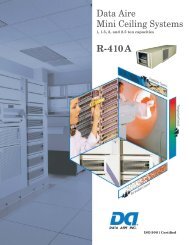
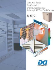
R-410A<br />
<strong>Data</strong> <strong><strong>Air</strong>e</strong> <strong>Series</strong><br />
<strong>Air</strong> <strong>Cooled</strong>,<br />
<strong>Water</strong>/<strong>Glycol</strong> <strong>Cooled</strong><br />
6 <strong>through</strong> <strong>30</strong> <strong>ton</strong> Dual Circuits<br />
R-410A<br />
1<br />
R-410A
<strong>Data</strong> <strong><strong>Air</strong>e</strong> ®<br />
… the pioneer and builder of the<br />
most complete line of<br />
precision cooling equipment<br />
<strong>Data</strong> <strong><strong>Air</strong>e</strong>’s fi rst precision cooling system was developed by data processing engineers who sought<br />
optimum environmental conditions for early computers. It was clear that “people comfort” air<br />
conditioning system were unable to meet the environmental requirements of computers and data<br />
processing equipment. Precision environmental control equipment with high sensible cooling ratios<br />
was a necessity. Problems with paper sticking , head crash, and static electricity were eliminated.<br />
Humidity fl uctuation were controlled saving possible electrical and mechanical failures and more<br />
importantly – Downtime. <strong>Data</strong> <strong><strong>Air</strong>e</strong>’s innovative response to the challenge of eliminating problems<br />
within the computer room environment was the start of wide use precision cooling.<br />
As in the past, <strong>Data</strong> <strong><strong>Air</strong>e</strong> is meeting today’s challenge of not only the computer room but also<br />
the ever expanding telecommunications industry where precision cooling is vital to our everyday<br />
communications. Telecommunication equipment requires a controlled environment with clean and<br />
properly distributed air. As in the computer room, the environment must be precisely controlled – 24<br />
hour a day, 365 days a year.<br />
<strong>Data</strong> <strong><strong>Air</strong>e</strong> produces solutions. We have offered environmental control solutions to meet specifi c needs<br />
in the smallest of places and in areas of thousands of square feet. We are prepared to assist you, your<br />
in-house engineering department, consulting engineer, or construction department in defi ning the<br />
proper solutions and bringing them to a predefi ned outcome.<br />
<strong>Data</strong> <strong><strong>Air</strong>e</strong> is committed to being the supplier of choice for environmental process cooling with<br />
fl exibility, reliability, and expertise required to meet our customer’s needs. To be successful, it is<br />
essential to be creative and use our resources to their fullest capabilities. The <strong>Data</strong> <strong><strong>Air</strong>e</strong> goal is to<br />
benefi t the employees, partners, and most of all – our customers with honesty and integrity.<br />
<strong>Data</strong> <strong><strong>Air</strong>e</strong> Delivers!
DATA AIRE DX SERIES - R410-A<br />
DIRECT EXPANSION UNITS<br />
AIR COOLED, WATER COOLED, GLYCOL COOLED<br />
(Separate brochure for Chilled <strong>Water</strong> <strong>Cooled</strong> units.)<br />
TABLE OF CONTENTS<br />
Design Features .................................................................................................5<br />
System Controls ................................................................................................8<br />
Options ............................................................................................................10<br />
Model Number Identifi cation ..........................................................................13<br />
Performance <strong>Data</strong><br />
<strong>Air</strong> <strong>Cooled</strong> ......................................................................................14<br />
<strong>Water</strong> <strong>Cooled</strong>..................................................................................20<br />
<strong>Glycol</strong> <strong>Cooled</strong> ................................................................................26<br />
Energy Saver ..................................................................................32<br />
Auxiliary Chilled <strong>Water</strong> .................................................................34<br />
Dimensional and Component Drawings<br />
6, 8, and 10 <strong>ton</strong> ...............................................................................36<br />
13 <strong>ton</strong> .............................................................................................40<br />
16, 20, and 26 <strong>ton</strong> ...........................................................................44<br />
<strong>30</strong> <strong>ton</strong> .............................................................................................48<br />
Plenum and Floorstand ..................................................................52<br />
Heat Exchangers ............................................................................53<br />
Standard Condenser Electrical <strong>Data</strong> ................................................................59<br />
Dimensional and Weight Information .............................................................60<br />
Guide Specifi cations ........................................................................................61<br />
<strong>Data</strong> <strong><strong>Air</strong>e</strong>, Inc. reserves the right to make design changes for the purpose of<br />
product improvement or to withdraw any design without notice.
PRECISION COOLING<br />
<strong>Data</strong> <strong><strong>Air</strong>e</strong> <strong>Series</strong> units offer precision environmental<br />
control that brings a standard of<br />
reliable performance to meet today’s market demands.<br />
<strong>Data</strong> <strong><strong>Air</strong>e</strong> systems are designed for data<br />
centers, telecommunication sites, or anywhere<br />
process cooling is required. <strong>Data</strong> <strong><strong>Air</strong>e</strong> <strong>Series</strong><br />
units are available in 6 <strong>through</strong> <strong>30</strong> nominal <strong>ton</strong>s<br />
with upfl ow or downfl ow air distribution either in<br />
air cooled or water/glycol cooled models. Each<br />
unit is factory run tested and put <strong>through</strong> a vigorous<br />
quality control procedure.<br />
COMFORT<br />
Computer rooms and other environmentally controlled<br />
spaces require air which is clean and<br />
properly distributed, with precisely controlled<br />
temperature and humidity. Building or “people<br />
comfort” cooling systems are not designed to<br />
meet these demands. <strong>Data</strong> <strong><strong>Air</strong>e</strong> <strong>Series</strong> units are<br />
designed to maintain temperature and humidity<br />
with properly distributed clean air required in<br />
environmentally controlled areas.<br />
HIGH PERFORMANCE/LOW COST<br />
Engineered for performance and reliability, each<br />
<strong>Data</strong> <strong><strong>Air</strong>e</strong> <strong>Series</strong> unit comes with <strong>Data</strong> <strong><strong>Air</strong>e</strong>’s<br />
commitment to excellence. This commitment<br />
began with <strong>Data</strong> <strong><strong>Air</strong>e</strong>’s fi rst process cooling<br />
unit and has continued for more than <strong>30</strong> years<br />
of building the industry’s fi nest environmental<br />
control equipment.<br />
DATA AIRE DELIVERS<br />
Standard ship cycle is <strong>30</strong> days from date<br />
of<br />
order. With an optional premium “quick ship”<br />
units can be expedited to ship in little as one<br />
week. All units are built to your specifi c order<br />
and specifi cation. Call your nearest <strong>Data</strong> <strong><strong>Air</strong>e</strong><br />
representative for more information.<br />
4
FRAME/CABINET<br />
Units are constructed with heliarc welded<br />
tubular steel frames. The tubular construction<br />
provides for maximum strength and ease of access.<br />
Side and front panels can be easily removed<br />
with quarter-turn fasteners allowing full access<br />
to all unit components. All panels include 1 inch<br />
thick, 11/2 pound density insulation for protection<br />
and sound attenuation.<br />
COIL SECTION<br />
Designed for draw <strong>through</strong> application, the computer<br />
selected dual circuited A-frame coil has an<br />
interwoven surface that increases unit effi ciency<br />
at low load conditions. <strong>Air</strong> is drawn <strong>through</strong> both<br />
circuits of the coil at low velocity providing effective<br />
surface exposure with minimum turbulence.<br />
<strong>Air</strong> bypass is provided to prevent saturated air<br />
from being introduced into the controlled space.<br />
The coil sits in a stainless steel drain pan.<br />
FAN SECTION<br />
The centrifugal, forward curved, double width,<br />
double inlet blower confi guration is engineered<br />
for quiet reliable operation. The dual belt driven<br />
variable pitch drive section provides adjustable<br />
air fl ow capability to match the load requirements<br />
of the controlled space. The draw <strong>through</strong> design<br />
insures even air distribution across the coil, low<br />
internal cabinet pressure losses and static sealing<br />
of the fi lter section. Motors are mounted on an<br />
adjustable slide base and have internal overload<br />
protection.<br />
DESIGN FEATURES<br />
5<br />
FILTER SECTION<br />
Units are provided with 4 inch deep, <strong>30</strong>% effi<br />
cient (based on ASHRAE Std. 52.1-1992),<br />
pleated fi lters. The fi lter section is accessible<br />
from the top or side on downfl ow units and the<br />
right hand side on upfl ow units.<br />
REHEAT<br />
Three stage electric reheat is standard. Lowwatt<br />
density, fi nned, tubular sheathed coils are<br />
constructed of stainless steel and provide ample<br />
capacity to maintain room dry bulb conditions<br />
during dehumidifi cation. Low-watt density coils<br />
eliminate ionization associated with open air<br />
electric resistance heating.<br />
HUMIDIFICATION<br />
<strong>Data</strong> <strong><strong>Air</strong>e</strong> <strong>Series</strong> units include an electric steam<br />
generator humidifi er with “quick change” disposable<br />
cylinders and auto-fl ush cycle. The steam<br />
generator humidifi er with its patented control system<br />
optimizes cylinder life and energy effi ciency<br />
by concentrating incoming water to a predetermined<br />
conductivity much higher than that of any<br />
entering water. The control system continuously<br />
monitors the conductivity in the cylinder <strong>through</strong><br />
its electronics which allows water to be fl ushed<br />
as often as is necessary to maintain the capacity<br />
at this design conductivity. The high design<br />
conductivity results in a minimum fl ushing of<br />
heated water which saves energy. The humidifi<br />
er is designed to allow all units at any voltage<br />
to produce full rated steam output capacity at an<br />
optimum low water level based on this design<br />
conductivity.
REFRIGERATION CIRCUITS<br />
Dual refrigeration circuits include high effi ciency hermetic scroll type compressors. Scroll compressors<br />
represent new yet proven compressor technology. Scroll compressors offer a combination of reliability,<br />
performance, and effi ciency. System noise is inherently quieter with scroll compressors.<br />
Scroll compressors offer:<br />
Simplicity - Fewer parts. Two components, a fi xed scroll and orbiting scroll, replace approximately 15 parts<br />
required to do the same work.<br />
Improved Starting Ability - With the scroll design the internal compression components always start unloaded<br />
even if the system pressures are not balanced. Since internal compressor pressures are always balanced<br />
at start-up, low voltage characteristics are excellent for scroll compressors.<br />
Energy Effi ciency - Scroll compressors are at least 10% more effi cient than reciprocating type compressors.<br />
The suction and discharge processes of a scroll compressor are physically separated. This reduces heat<br />
transfer between the suction and discharge gas. In a pis<strong>ton</strong> type compressor the cylinder is exposed to both<br />
suction and discharge gas. This results in high heat transfer reducing the compressor effi ciency.<br />
Scroll compressor compression and discharge processes are very smooth. Gas is compressed in approximately<br />
1 1/ 2 revolutions compared to less than 1/ 2 revolution for a pis<strong>ton</strong>.<br />
Scrolls require no valves. Pis<strong>ton</strong> compressors require both suction and discharge valves. No valves, no<br />
valve losses.<br />
Durability - Signifi cant design effort and system cost are required to protect pis<strong>ton</strong> compressors from slugging<br />
and debris. Scroll compressors are designed to be more tolerant of both liquid and debris.<br />
Reliability - Scrolls contain fewer moving parts resulting in greater reliability. Proven performance means<br />
fewer maintenance calls for fi eld personnel.<br />
Lower Sound - Systems properly designed with scroll compressors will be inherently quieter. On average,<br />
the compressor is up to 5 decibels quieter. (Sound characteristics of a scroll compressor are different than<br />
that of a reciprocating compressor. These do not effect system performance or reliability)<br />
These durable, heavy duty compressors have no gaskets or seals, eliminating the possibility of refrigerant or<br />
oil leaking into the controlled space or environment. Each refrigeration circuit includes built-in compressor<br />
overload protection, crankcase heater, fi lter drier, sight glass, adjustable expansion valve with external<br />
equalizer, low pressure override timer (air cooled units), manual reset high pressure control, and anti-short<br />
cycle timer.<br />
<strong>Water</strong>/glycol cooled units include counterfl ow condensers sized to provide the required capacity for heat<br />
rejection with minimum water/glycol fl ow and total pressure drop. Head pressure regulating valves control<br />
6
the condensing temperature and maintain required<br />
capacity at various water/glycol fl ow rates<br />
and temperatures.<br />
<strong>Air</strong> <strong>Cooled</strong> with Remote Outdoor <strong>Air</strong> <strong>Cooled</strong><br />
Condenser<br />
A wide range of outdoor condensers are available<br />
with vertical air discharge. Condensers<br />
manufactured by <strong>Data</strong> <strong><strong>Air</strong>e</strong> are sized to meet the<br />
required heat rejection and ambient conditions.<br />
The industrial duty condenser design includes<br />
an aluminum housing, aluminum fi nned copper<br />
tube coils, powder coated fan guards, energy effi<br />
cient, thermally protected direct drive motors,<br />
and variable speed fan control on the lead motor<br />
for proper control down to -20° F. Additional fan<br />
motors are controlled with ambient thermostats.<br />
<strong>Air</strong> <strong>Cooled</strong> with Indoor Condenser<br />
A wide range of fl oor mounted indoor condensers<br />
with horizontal intake and discharge are available<br />
for applications where an outdoor condenser<br />
cannot be used. Finished to match the indoor<br />
evaporator section, the condenser includes a centrifugal,<br />
forward curved, double width, double<br />
inlet blower engineered for quiet and reliable operation.<br />
The belt driven variable pitch drive section<br />
provides adjustable airfl ow. The motor has<br />
internal overload protection and is mounted on an<br />
adjustable slide base. Indoor condensers are provided<br />
with a factory mounted and piped receiver.<br />
The receiver has a head pressure control valve to<br />
maintain fl ooded condenser control.<br />
<strong>Air</strong> <strong>Cooled</strong> with Remote Outdoor Condensing<br />
Unit<br />
When compressors are required to be out of the<br />
controlled space, <strong>Data</strong> <strong><strong>Air</strong>e</strong> <strong>Series</strong> units are available<br />
with a remote outdoor condensing unit. The<br />
condensing unit includes the compressors with<br />
built-in overload protection, crankcase heater,<br />
fi lter drier, sight glass, and condenser coil. The<br />
REFRIGERATION CIRCUITS, continued<br />
7<br />
condenser coil is constructed with copper tubes<br />
and aluminum fi ns. The housing is aluminum<br />
with vertical air discharge. The condenser is<br />
variable speed fan control on the lead motor for<br />
head pressure control down to -20° F. Additional<br />
fan motors are controlled by ambient fan thermostats.<br />
<strong>Water</strong>/<strong>Glycol</strong> <strong>Cooled</strong> with Remote Outdoor Fluid<br />
Cooler<br />
Remote outdoor dry coolers (fl uid coolers) are<br />
available in a variety of sizes. Each dry cooler<br />
includes an aluminum housing, aluminum fi nned<br />
copper tube coil, powder coated fan guards, surge<br />
tank, pump contactor, and energy effi cient, thermally<br />
protected direct drive motors. Dry coolers<br />
with multiple motors have cycling control.<br />
<strong>Water</strong>/<strong>Glycol</strong> <strong>Cooled</strong> with Indoor Fluid Cooler<br />
When required a wide range of fl oor mounted indoor<br />
fl uid coolers (dry coolers) are available. The<br />
air intake and discharge are horizontal. Units are<br />
fi nished to match the indoor unit. The centrifugal,<br />
forward curved, double width, double inlet<br />
blower is engineered for quiet reliable operation.<br />
The belt driven variable pitch drive section<br />
provides adjustable airfl ow. The fan motor has<br />
internal overload protection and is mounted on<br />
an adjustable slide base. The unit control panel<br />
includes a pump contactor (units can be ordered<br />
with a factory mounted pump).
DATA ALARM PROCESSOR-III<br />
SYSTEM CONTROL<br />
The <strong>Data</strong> Alarm Processor-III (DAP III) offers the defi nitive answer for precision environmental control. The DAP-III control<br />
system not only controls and monitors temperature, humidity, airfl ow and cleanliness, it provides component run times, alarm history<br />
and an automatic self-test of the microprocessor on system start-up. All messages are presented in a clear vernacular format<br />
and sequentially displayed on a backlit, liquid crystal display (LCD).<br />
OPERATION – Highly reliable, fl at, sealed switches with tactile feedback allow unit on/off operation, menu selection for programming,<br />
operational information, diagnostics, and historical data. Multilevel password prevents unauthorized access. Alarm<br />
conditions are enunciated by an audible alarm. The alarm silence but<strong>ton</strong> will quiet the audible alarm but the display will continue<br />
to indicate the alarm condition until the problem is corrected.<br />
STANDARD FEATURES<br />
Two row, eight character, backlit LCD screen Stand alone panel<br />
Programmed settings saved in fl ash memory Microprocessor based<br />
Smooth keyboard type but<strong>ton</strong>s Automatic self-test diagnostics<br />
Real time clock with back-up battery USB port for software upgrades<br />
Forward and backward menu access All settings from face of panel<br />
<strong>Data</strong> base of unit and room conditions Multi-level password access<br />
Factory calibrated humidity sensor Battery backup for historical data<br />
Factory calibrated temperature sensor Menus factory programmed<br />
Power “ON” status contact<br />
OPERATIONAL FEATURES<br />
Automatic or manual restart Automatic compressor rotation<br />
Automatic reheat element rotation Hot water coil fl ush cycle<br />
Adjustable mode and stage response time Humidity anticipation<br />
Chilled water energy saver coil fl ush cycle Sequential load activation<br />
Compressor short cycle control on DX units Dehumidifi cation mode lockout<br />
Start time delay<br />
OPTIONAL FEATURES<br />
Energy saver (glycol) or auxiliary chilled water operation Humidifi er auto-fl ush cycle<br />
Periodical DX activation on Energy Saver system Three additional remote alarms<br />
Supplemental compressor in Energy Saver mode Discharge air temperature sensor<br />
Chilled water temperature sensor Modulating humidifi er control<br />
Four analog inputs (4-20 mA or 0-10 VDC signal) RS-485 Multi-drop network card<br />
Two analog outputs (0-10 VDC signal) Ethernet network card<br />
Underfl oor water detection cable LONTALK network card<br />
Fan speed control for optional plug fan or VFD<br />
DIAGNOSTIC and SERVICE FEATURES<br />
Alarms displayed in order of occurrence Manual diagnostic program<br />
Programmable delays for optional alarms Adjustable alarm limits<br />
Programmable remote alarm contact Select alarms optional disabled<br />
Four programmable optional alarm inputs Selectable audio alarm <strong>ton</strong>e<br />
Manual override for blower, cool 1/2, reheat 1, humidifi cation and water valve<br />
8
PROTECTIVE and SAFETY FEATURES<br />
Metal shell enclosure with sealed front control panel Watch dog timer<br />
Opto-coupler signal inputs Protected 24VAC power input<br />
Heavy ground planes and power foils Isolation transformer<br />
Switching power supply Fuses on all control boards<br />
CONDITIONS and DATA DISPLAYED<br />
Current percent of capacity utilized Temperature setpoint<br />
Current temperature Humidity setpoint<br />
Current humidity Unit or network identifi cation number*<br />
Current discharge air temperature* Zone number*<br />
Current chilled water temperature*<br />
FUNCTIONS DISPLAYED<br />
Cooling stages Energy Saver*<br />
Reheat stages Dehumidifi cation<br />
Chilled water fl ow percentage Humidifi cation<br />
9<br />
ALARMS<br />
High temperature warning Low temperature warning<br />
High humidity warning Low humidity warning<br />
High pressure/internal overload compressor 1 Low pressure compressor 1<br />
High pressure/internal overload compressor 2 Low pressure compressor 2<br />
Under fl oor water detection No air fl ow<br />
Firestat tripped, unit shutdown Dirty fi lter alarm<br />
Custom message (programmed by factory)* Humidity failure<br />
Chilled water temperature sensor problem* Manual override<br />
Low voltage warning Power failure restart<br />
Compressor short-cycle Temperature sensor problem<br />
Humidity sensor problem Maintenance required<br />
Local alarm* Discharge air sensor problem*<br />
Check humidifi er cylinder* Fan motor overload*<br />
No water fl ow* Smoke detector, unit shutdown*<br />
Standby pump on* Person to contact on alarm*<br />
HISTORICAL DATA<br />
Equipment run times Alarm history for last ten alarms<br />
High and low temperature in last 24 hours High and low humidity in last 24 hours<br />
Average percent of capacity last hour<br />
PROGRAMMABLE SETTINGS and SELECTIONS<br />
The user friendly Menus and Select but<strong>ton</strong>s used with the 10 menu groups permit step-by-step programming<br />
of many functions. The DAP III Operation Manual provides a complete and detailed guide to the settings and<br />
selections. Refer to it for specifi c ranges and settings.<br />
* - May require additional components and/or sensors.<br />
SYSTEM CONTROL, continued
Energy Saver Coil - The <strong>Data</strong> <strong><strong>Air</strong>e</strong> Energy<br />
Saver Coil is built into the system to provide<br />
total required capacity. Whenever the incoming<br />
water/glycol temperature is below 45 o F/7.2 o C,<br />
Energy Saver cooling is available. Energy Saver<br />
mode operates in the following range: return<br />
air setpoint plus deadband plus 2 degrees. The<br />
Energy Saver will operate providing there is a<br />
need for cooling. The valve will open at setpoint<br />
plus deadband. The valve will modulate as long<br />
as the space is between setpoint plus deadband<br />
plus 2 degrees. If the temperature falls below<br />
the deadband minus setpoint, the valve will close<br />
and the space is considered satisfi ed. While still<br />
in Energy Saver with the valve modulating, if the<br />
temperature goes beyond setpoint plus 2 degrees,<br />
the Energy Saver valve will close and DX cooling<br />
will begin.<br />
The Energy Saver coil includes the next size motor,<br />
3-way pressure control valve on the condenser<br />
water circuit, and 3-way valve on the economy<br />
coil. Common piping for coil and condensers is<br />
provided.<br />
Energy Saver/Compressor Supplement - Units<br />
with Energy Saver option can be provided with<br />
compressor supplement if the Energy Saver is<br />
not suffi cient as a stand alone system. When the<br />
incoming water/glycol temperature is below the<br />
setpoint of the water changeover thermostat, the<br />
Energy Saver is enabled (even if there is no call<br />
for cooling). Upon a call for cooling (setpoint<br />
plus deadband), the valve will open proportionally<br />
- 10% for each 0.1 o above setpoint plus deadband.<br />
The compressor will come on at setpoint<br />
plus deadband plus 1 o (the valve is 100% open at<br />
this point). The compressor will go off at setpoint<br />
plus deadband plus 0.7 o . The valve will close<br />
proportionally - 10% for each 0.1 o below setpoint<br />
plus deadband. An air discharge sensor is factory<br />
installed.<br />
OPTIONS<br />
10<br />
Auxiliary Chilled <strong>Water</strong> Coil - Where an existing<br />
chilled water loop is available, units can be<br />
fi tted with an auxiliary chilled water coil. Units<br />
will operate using the chilled water for cooling.<br />
Upon a loss of water fl ow or an increase in room<br />
temperature the system will bring on compressor<br />
(DX) cooling. The Auxiliary Chilled <strong>Water</strong> coil<br />
includes the next size motor. Separate piping is<br />
provided for the chilled water coil and refrigeration<br />
connections.<br />
Auxiliary Chilled <strong>Water</strong> Coil/Compressor Supplement<br />
- The Auxiliary Chilled <strong>Water</strong> Coil can<br />
be provided with compressor supplement for<br />
extended savings by allowing the compressor to<br />
supplement operation as needed when the chilled<br />
water is not suffi cient on a stand alone basis. An<br />
air discharge sensor is factory installed. (See Energy<br />
Saver/Compressor Supplement for details)<br />
Remote Temperature and Humidity Sensors<br />
- Temperature and humidity sensors may be<br />
ordered for remote wall mounting. Sensors are<br />
provided in a wall mount plastic case for remote<br />
sensing of temperature and humidity. 25 feet of<br />
shielded cable is provided for fi eld wiring.<br />
Smoke Detector - A unit mounted smoke detector<br />
will shut down the unit if smoke is sensed. The<br />
unit mounted microprocessor control will sound<br />
an alarm and display a “SMOKE DETECTED”<br />
message. The smoke detector is mounted in the<br />
return air stream and is provided with auxiliary<br />
contacts.<br />
Unit Mounted Disconnect - A unit mounted<br />
nonautomatic disconnect switch is installed in<br />
the high voltage electrical section. The operating<br />
mechanism (handle) protrudes <strong>through</strong> the decorative<br />
exterior panel. The operating mechanism<br />
prevents access to the high voltage electrical<br />
components by not allowing entry until switched<br />
to the “OFF” position.
Tandem Scroll Compressors - Units may be<br />
ordered with tandem scroll compressors when<br />
four stage compressor control is required. Units<br />
remain dual circuited. Tandem scrolls offer the<br />
inherent advantages of scroll technology: higher<br />
effi ciency, increased reliability, lower sound, and<br />
excellent liquid handling.<br />
Scroll tandems offer two steps of modulation so<br />
that one or both compressors (per circuit) can run<br />
depending upon the load of the system, resulting<br />
in part-load effi ciency equal to full load effi -<br />
ciency. Two-step modulation is possible because<br />
of a carefully designed tubing confi guration and<br />
the scroll’s superior ability to tolerate liquid.<br />
The built-in discharge check valve, present in all<br />
scroll compressors, effectively prevents liquid<br />
migration in the off compressor. Oil migration<br />
is controlled with two specially designed oil and<br />
gas equalization lines. Adding this option to <strong>30</strong><strong>ton</strong><br />
unit will increase cabinet size to 144”. (See<br />
Supplement TS1-99: Tandem Scroll Technical<br />
Performance)<br />
Semi-Hermetic Compressors - Cast iron semihermetic<br />
compressors are available on all <strong>Data</strong><br />
<strong><strong>Air</strong>e</strong> <strong>Series</strong> units. Semi-hermetic compressors<br />
are mounted on vibration isolators and have builtin<br />
overload protection. The compressors also<br />
include oil sight glass, reversible oil pump for<br />
forced feed lubrication, and suction line strainer.<br />
Units with semi-hermetic compressor option also<br />
include solenoid valves and muffl ers. Maximum<br />
rpm is 1750.<br />
Four Step Control (Cylinder Unloading) - Units<br />
with semi-hermetic compressors may be ordered<br />
with four step control for periods of low load conditions.<br />
Cylinder unloaders on one head of each<br />
compressor reduces compressor cooling capacity.<br />
Four steps of cooling are available to meet changing<br />
room conditions.<br />
Compressor Sequence:<br />
Step 1 Lead compressor starts with unloader<br />
valve activated<br />
Step 2 Lead compressor running at full load<br />
Step 3 Lag compressor starts with unloader<br />
valve activated<br />
Step 3 Lag compressor running at full load<br />
OPTIONS, continued<br />
11<br />
Hot Gas Bypass - Hot gas bypass is available<br />
for changing load conditions. The hot gas bypass<br />
valve is installed between the compressor<br />
discharge line and the leaving side of the expansion<br />
valve <strong>through</strong> a side outlet distributor. The<br />
system with the evaporator under full load will<br />
maintain pressure on the leaving side of the hot<br />
gas bypass valve to keep the valve port closed.<br />
Should the load on the evaporator decrease to<br />
the point where the coil is below the desired<br />
setting, the pressure on the discharge of the hot<br />
gas bypass will put pressure on the diaphragm<br />
overcoming the spring pressure of the seat and<br />
allowing some hot gas to mix with the normal<br />
liquid discharge of the expansion valve raising<br />
the evaporator pressure. This reduces the cooling<br />
capacity of the unit to match the load. The hot<br />
gas bypass valve can be adjusted to “fi ne tune”<br />
the unit to room conditions.<br />
Humidifi er Modulating Control - Modulating<br />
control may be added to the unit’s steam generator<br />
humidifi er. Modulating control will allow the<br />
humidifi er to match its output to the signal from<br />
the humidity control. A self-regulating auto fl ush<br />
is included.<br />
Hot <strong>Water</strong> Reheat - Where hot water is available,<br />
a water coil for reheat is offered. The coil<br />
is designed for 150 psi maximum water pressure<br />
and includes a 2-way valve (a 3-way is also<br />
available). Units with the hot water reheat do not<br />
include electric reheat. Supplemental reheat may<br />
be ordered.<br />
Hot Gas Reheat - The unit’s hot gas discharge<br />
may be used for reheat and maximum system<br />
effi ciency. Supplemental electric reheat may be<br />
ordered in addition to the hot gas reheat.<br />
3-Way <strong>Water</strong> Regulating Valve - 3-way water<br />
regulating valves are available on water and<br />
glycol cooled units to replace the standard 2-way<br />
valve. The 3-way valve controls the water/glycol<br />
fl ow rate to maintain the required capacity under<br />
varying conditions. This option is recommended<br />
on units with dual pump applications.
Upfl ow <strong>Air</strong> Discharge Plenum - Upfl ow air<br />
discharge plenums are fully insulated with front<br />
discharge grille. Side grilles for both or one side<br />
are available. Plenums are 18” high and painted<br />
to match the unit’s color.<br />
Floorstands - Floorstands are adjustable (± 2<br />
inches) and may be ordered with factory installed<br />
turning vane or with seismic construction.<br />
High Effi ciency Filters - Standard fi lters are<br />
rated at <strong>30</strong>% (per ASHRAE Std. 52-76). Higher<br />
effi ciency fi lters are available (consult factory<br />
regarding effi ciency percentage and unit static<br />
pressures).<br />
Condensate Pumps - Condensate pumps may be<br />
ordered factory installed or shipped loose for fi eld<br />
installation. Condensate pumps are complete<br />
with sump, motor, and automatic control. Pumps<br />
shipped loose are available in 115, 2<strong>30</strong>, or 460<br />
volts.<br />
Pump Ratings:<br />
2<strong>30</strong> volt:<br />
with check valve - 40 GPH at 20 feet<br />
without check valve - 1<strong>30</strong> GPH at 40 feet<br />
460 volt:<br />
with check valve - 50 GPH at 20 feet<br />
without check valve - 270 GPH at 40 feet<br />
Pump Package - Centrifugal pump packages are<br />
available to circulate water or water/glycol solutions.<br />
Pumps are available in various horsepower<br />
and voltages. Both 3400 and 1750 rpm pumps<br />
are available as an option. On dual pump applica<strong>ton</strong>s<br />
it is recommended that a 3-way water<br />
regulating valve be used in lieu of the standard<br />
2-way valve.<br />
Pump Enclosure - Pump enclosures are available<br />
for either single or dual pump applications.<br />
Pump enclosures are vented and weather resistant.<br />
When ordered with pumps, the pumps are<br />
factory mounted in the enclosure ready for fi eld<br />
piping and wiring.<br />
OPTIONS, continued<br />
12<br />
Integral Pump Enclosures - Pumps may be factory<br />
mounted as an integral part of the dry cooler.<br />
A <strong>30</strong>” extension is added to the dry cooler.<br />
Pumps are pre-piped and wired and includes<br />
shut-off valves. A fl ow switch is included with<br />
dual pumps.<br />
Pump Auto-Changeover - Dual pump packages<br />
may be provided with a pump auto-changeover<br />
control and NEMA 4 fl ow switch (fi eld installed).<br />
The pump auto-changeover control is factory<br />
wired and mounted in the dry cooler control box.<br />
The pump auto-changeover control provides automatic<br />
pump changeover in the event of a pump<br />
failure. Upon pump changeover, an audible<br />
alarm will sound at the indoor unit and a message<br />
(“STANDBY PUMP ON”) will be displayed on<br />
the indoor unit microprocessor display.<br />
Extended Compressor Warranty - Extended<br />
compressor warranties are available from <strong>Data</strong><br />
<strong><strong>Air</strong>e</strong>. Contact your local representative for one<br />
that best suites your needs.
MODEL NUMBER IDENTIFICATION<br />
13
MODEL NUMBER DAAD/U-06 DAAD/U-08 DAAD/U-10 DAAD/U-13 DAAD/U-16 DAAD/U-20 DAAD/U-26 DAAD/U-<strong>30</strong><br />
R-410A<br />
CAPACITY in Btu/hr - Gross<br />
80 o DB/67 o WB Total 76,800 108,600 128,400 165,600 214,900 266,500 326,900 388,200<br />
50% RH Sensible 58,<strong>30</strong>0 84,900 106,400 126,600 160,<strong>30</strong>0 204,900 243,400 <strong>30</strong>1,700<br />
75 o DB/62.5 o WB Total 71,600 100,500 119,<strong>30</strong>0 153,500 199,700 246,800 <strong>30</strong>3,700 360,600<br />
50% RH Sensible 56,<strong>30</strong>0 81,600 102,400 121,800 154,700 197,200 235,100 290,700<br />
75 o DB/61 o WB Total 69,500 97,100 115,800 149,<strong>30</strong>0 193,800 240,400 294,<strong>30</strong>0 350,100<br />
45% RH Sensible 60,200 87,200 109,600 1<strong>30</strong>,<strong>30</strong>0 165,000 211,100 250,400 310,900<br />
72 o DB/60 o WB Total 68,400 95,700 113,900 145,900 190,600 235,000 289,800 344,000<br />
50% RH Sensible 55,100 79,700 99,900 119,000 151,400 192,500 2<strong>30</strong>,100 284,100<br />
72 o DB/58.6 o WB Total 66,900 93,000 110,600 142,000 185,400 229,700 283,<strong>30</strong>0 334,400<br />
45% RH Sensible 58,600 84,600 106,<strong>30</strong>0 126,100 160,200 204,700 244,100 <strong>30</strong>1,400<br />
BLOWER SECTION<br />
<strong>Air</strong>fl ow - CFM 2,700 3,600 4,500 4,800 6,400 8,000 9,000 12,000<br />
Standard Motor - horsepower 2 2 3 3 3 5 7.5 3<br />
External static pressure (E.S.P.) - inches of W.G. 0.5 0.5 0.5 0.5 0.5 0.5 0.5 0.5<br />
Number of motors/fans 1/1 1/1 1/1 1/1 1/2 1/2 1/2 3/3<br />
Maximum E.S.P. Downfl ow 0.8 1.0 1.2 0.7 1.0 1.2 1.5 1.5<br />
(Standard motor) Upfl ow 0.7 0.9 1.0 0.6 0.9 1.1 1.5 1.5<br />
Maximum E.S.P. Downfl ow 0.9 1.5 1.5 1.5 1.4 1.5 1.5 1.5<br />
(Next Size motor) Upfl ow 0.9 1.5 1.0 1.5 1.3 1.5 1.5 1.5<br />
Next size motor horsepower 3 3 5 5 5 7.5 10 5<br />
COMPRESSORS<br />
Type:<br />
Hermetic scroll Standard Standard Standard Standard Standard Standard Standard Standard<br />
Semi-Hermetic N/A N/A N/A N/A N/A N/A N/A N/A<br />
Number 2 2 2 2 2 2 2 2<br />
Refrigerant type R-410A R-410A R-410A R-410A R-410A R-410A R-410A R-410A<br />
EVAPORATOR COIL<br />
Face area - sq. ft. 12.2 12.2 12.2 14.5 24.4 24.4 24.4 32.5<br />
Rows of coils 2 3 4 5 3 4 5 4<br />
Face velocity - FPM 221 295 369 331 262 328 369 369<br />
REHEAT SECTION<br />
AIR COOLED: Performance data at STANDARD airfl ow<br />
Electric Standard Standard Standard Standard Standard Standard Standard Standard<br />
kW 15 15 15 15 22.5 22.5 22.5 <strong>30</strong><br />
Capacity - Btu/hr 51,225 51,225 51,225 51,225 76,835 76,835 76,835 102,450<br />
Hot gas Optional Optional Optional Optional Optional Optional Optional Optional<br />
Capacity - Btu/hr 26,000 38,000 42,200 48,000 64,000 81,000 101,000 126,000<br />
Steam Optional Optional Optional Optional Optional Optional Optional N/A<br />
Capacity - Btu/hr Downfl ow 105,500 115,000 121,000 126,000 90,000 210,000 2<strong>30</strong>,000 N/A<br />
Upfl ow 60,000 65,000 69,000 72,000 108,000 120,000 1<strong>30</strong>,000 N/A<br />
Hot water Optional Optional Optional Optional Optional Optional Optional N/A<br />
Capacity - Btu/hr Downfl ow 70,000 81,000 86,000 90,000 1<strong>30</strong>,000 145,000 160,000 N/A<br />
Upfl ow 34,<strong>30</strong>0 44,800 47,500 49,400 74,200 82,000 90,700 N/A<br />
14
AIR COOLED: Performance data at STANDARD airfl ow<br />
MODEL NUMBER DAAD/U-06 DAAD/U-08 DAAD/U-10 DAAD/U-13 DAAD/U-16 DAAD/U-20 DAAD/U-26 DAAD/U-<strong>30</strong><br />
HUMIDIFIER SECTION<br />
Steam generator Standard Standard Standard Standard Standard Standard Standard Standard<br />
Capacity lbs/hr (Adjustable) 10-<strong>30</strong> 10-<strong>30</strong> 10-<strong>30</strong> 10-<strong>30</strong> 10-<strong>30</strong> 10-<strong>30</strong> 10-<strong>30</strong> 10-<strong>30</strong><br />
kW 3.3-10.2 3.3-10.2 3.3-10.2 3.3-10.2 3.3-10.2 3.3-10.2 3.3-10.2 3.3-10.2<br />
Steam grid Optional Optional Optional Optional Optional Optional Optional Optional<br />
Capacity lbs/hr at 15 psi 31 31 31 31 31 31 31 31<br />
FILTER SECTION* (4 inch thick, <strong>30</strong>% effi cient, based on ASHRAE Std. 52-76)<br />
Quantity /size Downfl ow 3/20x25 3/20x25 3/20x25 2/20x25 3/20x25 3/20x25 3/20x25 3/20x25<br />
- - - 2/16x25 2/16x25 2/16x25 2/16x25 4/16x25<br />
CONNECTION SIZES<br />
Upfl ow 2/20x25 2/20x25 2/20x25 3/20x25 2/20x25 2/20x25 2/20x25 2/20x25<br />
- - - - 2/16x25 2/16x25 2/16x25 4/16x25<br />
Liquid line - O.D. Copper (2 per unit) 1/2 1/2 1/2 5/8 5/8 5/8 7/8 7/8<br />
Hot gas line - O.D. Copper (2 per unit) 1/2 5/8 5/8 3/4 3/4 3/4 7/8 7/8<br />
Suction line* - O.D. Copper (2 per unit) 7/8 7/8 1 1/8 1 1/8 1 3/8 1 3/8 1 3/8 1 3/8<br />
Condensate drain 3/4 3/4 3/4 3/4 3/4 3/4 3/4 3/4<br />
Humidifi er supply 1/4 1/4 1/4 1/4 1/4 1/4 1/4 1/4<br />
NOTE: Refer to Operation and Maintenance manual for recommended pipe sizing between unit and condenser.<br />
ELECTRICAL SECTION Standard Motor<br />
Electrical data based on STANDARD unit: electric reheat - YES, steam generator - YES and STANDARD MOTOR.<br />
208-2<strong>30</strong>/3/60 FLA/MCA/MOP 61/75/80 70/81/90 78/90/100 87/100/110 101/124/125 110/134/150 151/171/200 164/199/225<br />
460/3/60 FLA/MCA/MOP 28/34/35 35/41/45 36/42/45 43/49/50 49/60/70 53/64/70 69/78/90 77/93/110<br />
575/3/60 FLA/MCA/MOP 22/27/<strong>30</strong> 25/29/<strong>30</strong> 29/33/35 33/38/45 38/47/50 41/50/60 59/66/80 64/77/90<br />
Electrical data based on: electric reheat - NO, steam generator - YES and STANDARD MOTOR.<br />
208-2<strong>30</strong>/3/60 FLA/MCA/MOP 61/71/80 70/81/90 78/90/100 87/100/110 97/112/125 110/125/150 151/171/200 165/186/225<br />
460/3/60 FLA/MCA/MOP 28/33/35 35/41/45 36/42/45 43/49/50 50/58/70 55/63/70 69/78/90 79/89/110<br />
575/3/60 FLA/MCA/MOP 22/25/<strong>30</strong> 25/29/<strong>30</strong> 29/33/35 33/38/45 38/44/50 41/47/50 59/66/80 68/76/90<br />
Electrical data based on: electric reheat - YES, steam generator - NO and STANDARD MOTOR.<br />
208-2<strong>30</strong>/3/60 FLA/MCA/MOP 61/75/80 65/80/90 71/86/90 75/92/100 101/124/125 110/134/150 134/162/175 164/199/225<br />
460/3/60 FLA/MCA/MOP 28/34/35 31/39/40 33/40/45 36/44/50 49/60/70 53/64/70 62/74/90 77/93/110<br />
575/3/60 FLA/MCA/MOP 22/27/<strong>30</strong> 24/29/<strong>30</strong> 26/32/35 28/34/40 38/47/50 41/50/60 51/62/70 64/77/90<br />
Electrical data based on: electric reheat - NO, steam generator - NO and STANDARD MOTOR.<br />
208-2<strong>30</strong>/3/60 FLA/MCA/MOP 32/36/45 41/46/60 49/55/70 58/65/90 69/76/100 81/90/110 123/135/175 137/151/200<br />
460/3/60 FLA/MCA/MOP 15/17/20 22/25/<strong>30</strong> 23/26/35 <strong>30</strong>/33/45 38/42/50 42/47/60 56/62/80 66/73/100<br />
575/3/60 FLA/MCA/MOP 11/12/15 15/16/20 19/20/25 23/25/<strong>30</strong> 28/31/40 31/34/45 48/53/70 57/63/80<br />
* Only applicable when compressors are in the condensing unit rather than evaporator section.<br />
FLA - Full load amps<br />
MCA - Minimum circuit ampacity (wire sizing amps)<br />
MOP - Maximum rating of the overcurrent protective device<br />
* Units with Auxiliary Chilled <strong>Water</strong> Coils have different fi lter quantities as those listed in this section. Refer to dimensional data sheets.<br />
15 R-410A
R-410A<br />
AIR COOLED: Performance data at STANDARD airfl ow<br />
MODEL NUMBER DAAD/U-06 DAAD/U-08 DAAD/U-10 DAAD/U-13 DAAD/U-16 DAAD/U-20 DAAD/U-26 DAAD/U-<strong>30</strong><br />
ELECTRICAL SECTION Next Size Motor<br />
Electrical data based on: electric reheat - YES, steam generator humidifi er - YES and NEXT SIZE MOTOR.<br />
208-2<strong>30</strong>/3/60 FLA/MCA/MOP 63/77/80 72/83/90 84/96/110 93/106/110 107/1<strong>30</strong>/150 116/140/150 161/181/225 183/218/253<br />
460/3/60 FLA/MCA/MOP 29/35/40 36/42/45 39/44/50 45/51/60 52/63/70 56/68/70 73/82/100 84/101/110<br />
575/3/60 FLA/MCA/MOP 23/28/<strong>30</strong> 26/<strong>30</strong>/35 31/35/40 35/40/45 40/49/50 44/53/60 60/68/80 70/83/90<br />
Electrical data based on: electric reheat - NO, steam generator humidifi er - YES and NEXT SIZE MOTOR.<br />
208-2<strong>30</strong>/3/60 FLA/MCA/MOP 63/73/80 72/83/90 84/96/110 93/106/110 103/118/125 115/1<strong>30</strong>/150 161/181/225 184/205/253<br />
460/3/60 FLA/MCA/MOP 29/34/35 36/42/45 39/44/50 45/51/60 53/60/70 59/66/80 73/82/100 86/96/110<br />
575/3/60 FLA/MCA/MOP 22/26/<strong>30</strong> 26/<strong>30</strong>/35 31/35/40 35/40/45 40/46/50 45/50/60 60/68/80 74/82/100<br />
Electrical data based on: electric reheat - YES, steam generator humidifi er - NO and NEXT SIZE MOTOR.<br />
208-2<strong>30</strong>/3/60 FLA/MCA/MOP 63/77/80 68/83/90 77/92/100 81/98/110 107/1<strong>30</strong>/150 116/140/150 144/172/200 183/218/253<br />
460/3/60 FLA/MCA/MOP 29/35/40 33/40/45 35/42/45 38/46/50 52/63/70 56/68/70 65/78/90 84/101/110<br />
575/3/60 FLA/MCA/MOP 23/28/<strong>30</strong> 25/<strong>30</strong>/35 28/34/35 <strong>30</strong>/36/40 40/49/50 44/53/60 53/63/70 70/83/90<br />
Electrical data based on: electric reheat - NO, steam generator humidifi er - NO and NEXT SIZE MOTOR.<br />
208-2<strong>30</strong>/3/60 FLA/MCA/MOP 35/38/50 44/48/60 56/61/80 65/71/90 75/82/110 87/95/125 133/145/175 155/169/225<br />
460/3/60 FLA/MCA/MOP 16/18/20 23/26/35 26/28/35 32/35/45 40/44/60 46/50/60 60/66/80 74/80/100<br />
575/3/60 FLA/MCA/MOP 12/13/15 16/17/20 21/22/<strong>30</strong> 25/27/35 <strong>30</strong>/33/45 34/37/50 50/55/70 63/69/90<br />
FLA - full load amps MCA - Minimum circuit amps (wire size amps) MOP - Maximum rating of the overcurrent protective device<br />
COMPRESSOR FLA -full load amps<br />
208-2<strong>30</strong>/3/60 13.1 17.6 20.5 25.0 <strong>30</strong>.1 33.3 51.3 55.8<br />
460/3/60 6.1 9.6 9.6 12.8 16.7 17.9 23.1 26.9<br />
575/3/60 4.4 6.1 7.6 9.6 12.2 12.8 19.9 23.7<br />
CONDENSER Remote air cooled outdoor<br />
Standard selection at 95° F ambient at sea level<br />
Evaporative model DAAD/U-06 DAAD/U-08 DAAD/U-10 DAAD/U-13 DAAD/U-16 DAAD/U-20 DAAD/U-26 DAAD/U-<strong>30</strong><br />
Condenser model DARC-06 DARC-09 DARC-11 DARC-15 DARC-17 DARC-21 DARC-28 DARC-<strong>30</strong><br />
Selection at 100° F ambient at sea level<br />
Evaporative model DAAD/U-06 DAAD/U-08 DAAD/U-10 DAAD/U-13 DAAD/U-16 DAAD/U-20 DAAD/U-26 DAAD/U-<strong>30</strong><br />
Condenser model DARC-07 DARC-11 DARC-15 DARC-17 DARC-21 DARC-24 DARC-<strong>30</strong> DARC-40<br />
Selection at 105° F ambient at sea level<br />
Evaporative model DAAD/U-06 DAAD/U-08 DAAD/U-10 DAAD/U-13 DAAD/U-16 DAAD/U-20 DAAD/U-26 DAAD/U-<strong>30</strong><br />
Condenser model DARC-11 DARC-15 DARC-15 DARC-21 DARC-24 DARC-<strong>30</strong> DARC-40 DARC-50<br />
(Note: Refer to pages 57 and 61 for electrical data on remote air cooled condensers.)<br />
* * * The following section has no reference to column headings * * *<br />
EVAPORATOR FAN MOTOR FLA - full load amps<br />
Horsepower 1.0 1.5 2.0 3.0 5.0 7.5 10.0<br />
208-2<strong>30</strong>/3/60 3.6 4.8 6.2 9.0 14.6 23.0 29.0<br />
460/3/60 1.8 2.4 3.1 4.4 6.6 11.0 14.0<br />
575/3/60 1.4 2.0 2.5 3.3 5.3 8.6 10.0<br />
16
MODEL NUMBER DAAD/U-06 DAAD/U-08 DAAD/U-10 DAAD/U-13 DAAD/U-16 DAAD/U-20 DAAD/U-26 DAAD/U-<strong>30</strong><br />
CAPACITY in Btu/hr - Gross<br />
80° F/67° WB Total 79,900 111,700 132,500 169,500 222,900 271,700 333,200 397,900<br />
50% RH Sensible 65,000 94,900 119,700 138,100 180,800 218,900 258,200 329,<strong>30</strong>0<br />
75° DB/62.5° WB Total 74,200 103900 122,800 157,<strong>30</strong>0 207,200 251,800 <strong>30</strong>9,800 369,<strong>30</strong>0<br />
50% RH Sensible 62,500 91,100 114,900 132,700 173,900 210,<strong>30</strong>0 248,900 316,<strong>30</strong>0<br />
75° DB/61° WB Total 71,900 100,600 118,800 152,400 201,<strong>30</strong>0 245,600 <strong>30</strong>0,400 357,900<br />
45% RH Sensible 67,100 97,900 118,600 142,200 186,600 226,000 266,000 339,400<br />
72° DB/60° WB Total 70,800 99,200 117,000 150,000 197,700 239,800 295,700 352,200<br />
50% RH Sensible 61,000 88,900 112,000 129,500 169,700 205,100 243,400 <strong>30</strong>8,500<br />
72° DB/58.6° WB Total 68,800 96,<strong>30</strong>0 113,<strong>30</strong>0 146,000 194,000 234,500 289,100 343,800<br />
45% RH Sensible 64,900 94,700 112,700 137,800 181,<strong>30</strong>0 218,600 258,700 329,000<br />
BLOWER SECTION<br />
<strong>Air</strong>fl ow - CFM 3,<strong>30</strong>0 4,400 5,500 5,600 8,000 9,000 10,000 14,000<br />
Standard motor - horsepower 3 3 5 5 5 7.5 7.5 3<br />
External static pressure (E.S.P.) - inches of W.G. 0.5 0.5 0.5 0.5 0.5 0.5 0.5 0.5<br />
Number of motors/fans 1/1 1/1 1/1 1/1 1/2 1/2 1/2 3/3<br />
Maximum E.S.P. Downfl ow 0.9 1.2 1.2 1.1 1.2 1.5 1.0 0.6<br />
(Standard Motor) Upfl ow 0.7 0.9 1.0 0.6 0.9 1.1 1.6 0.5<br />
Maximum E.S.P. Downfl ow 1.5 1.5 1.2 1.1 1.5 1.5 1.5 1.5<br />
(Next Size Motor) Upfl ow 1.5 1.5 0.9 1.0 1.5 1.5 1.5 1.5<br />
Next size motor - horsepower 5 5 7.5 7.5 7.5 10 10 5<br />
COMPRESSORS<br />
Type:<br />
Hermetic scroll Standard Standard Standard Standard Standard Standard Standard Standard<br />
Semi-hermetic N/A N/A N/A N/A N/A N/A N/A N/A<br />
Number 2 2 2 2 2 2 2 2<br />
Refrigerant type R-410A R-410A R-410A R-410A R-410A R-410A R-410A R-410A<br />
EVAPORATOR COIL<br />
Face area - sq ft . 12.2 12.2 12.2 14.5 24.4 24.4 24.4 32.5<br />
Rows of coils 2 3 4 5 3 4 5 4<br />
Face velocity - fpm 271 361 451 386 328 369 410 431<br />
REHEAT SECTION<br />
AIR COOLED: Performance data at OPTIONAL airfl ow<br />
Electric Standard Standard Standard Standard Standard Standard Standard Standard<br />
kW 15 15 15 15 22.5 22.5 22.5 <strong>30</strong><br />
Capacity - Btu/hr 51,225 51,225 51,225 51,225 76,835 76,835 76,835 102,450<br />
Hot gas Optional Optional Optional Optional Optional Optional Optional Optional<br />
Capacity - Btu/hr 26,000 38,000 42,200 48,000 64,000 81,000 101,000 126,000<br />
Steam Optional Optional Optional Optional Optional Optional Optional N/A<br />
Capacity - Btu/hr Downfl ow 105,500 115,000 121,000 126,000 190,000 210,000 2<strong>30</strong>,000 N/A<br />
Upfl ow 60,000 65,000 69,000 72,000 108,000 120,000 1<strong>30</strong>,000 N/A<br />
Hot water Optional Optional Optional Optional Optional Optional Optional N/A<br />
Capacity - Btu/hr Downfl ow 70,000 81,000 86,000 90,000 1<strong>30</strong>,000 145,000 160,000 N/A<br />
Upfl ow 34,<strong>30</strong>0 44,800 47,500 49,400 74,200 82,000 90,700 N/A<br />
17 R-410A
R-410A<br />
AIR COOLED: Performance data at OPTIONAL airfl ow<br />
MODEL NUMBER DAAD/U-06 DAAD/U-08 DAAD/U-10 DAAD/U-13 DAAD/U-16 DAAD/U-20 DAAD/U-26 DAAD/U-<strong>30</strong><br />
HUMIDIFIER SECTION<br />
Steam generator Standard Standard Standard Standard Standard Standard Standard Standard<br />
Capacity - lb/hr (Adjustable) 10-<strong>30</strong> 10-<strong>30</strong> 10-<strong>30</strong> 10-<strong>30</strong> 10-<strong>30</strong> 10-<strong>30</strong> 10-<strong>30</strong> 10-<strong>30</strong><br />
kW 3.3-10.2 3.3-10.2 3.3-10.2 3.3-10.2 3.3-10.2 3.3-10.2 3.3-10.2 3.3-10.2<br />
Steam grid Optional Optional Optional Optional Optional Optional Optional Optional<br />
Capacity - lb/hr at 15 psi 31 31 31 31 31 31 31 31<br />
FILTER SECTION (4 inch thick, <strong>30</strong>% effi cient, based on ASHRAE Std. 52-76)<br />
Quantity/Size Downfl ow 3/20x25 3/20x25 3/20x25 2/20x25 3/20x25 3/20x25 3/20x25 3/20x25<br />
- - - 2/16x25 2/16x25 2/16x25 2/16x25 4/16x25<br />
CONNECTION SIZES<br />
Upfl ow 2/20x25 2/20x25 2/20x25 3/20x25 2/20x25 2/20x25 2/20x25 2/20x25<br />
- - - - 2/16x25 2/16x25 2/16x25 4/16x25<br />
Liquid line - O.D. Copper (2 per unit) 1/2 1/2 1/2 5/8 5/8 5/8 7/8 7/8<br />
Hot gas line - O.D. Copper (2 per unit) 1/2 5/8 5/8 3/4 3/4 3/4 7/8 7/8<br />
Suction line* - O.D. Copper (2 per unit) 7/8 7/8 1 1/8 1 1/8 1 3/8 1 3/8 1 3/8 1 3/8<br />
Condensate drain 3/4 3/4 3/4 3/4 3/4 3/4 3/4 3/4<br />
Humidifi er supply 1/4 1/4 1/4 1/4 1/4 1/4 1/4 1/4<br />
(Note: Refer to Operation and Maintenance manual for recommended pipe sizing between unit and condenser.)<br />
ELECTRICAL SECTION Standard Motor<br />
Electrical data based on STANDARD unit: electric reheat - YES, steam generator humidifi er - YES, and STANDARD MOTOR.<br />
208-2<strong>30</strong>/3/60 FLA/MCA/MOP 63/77/80 72/83/90 84/96/110 93/106/110 107/1<strong>30</strong>/150 116/140/150 151/171/200 164/199/225<br />
460/3/60 FLA/MCA/MOP 29/35/40 36/42/45 39/44/50 45/51/60 52/63/70 56/68/70 69/78/90 77/93/110<br />
575/3/60 FLA/MCA/MOP 23/28/<strong>30</strong> 26/<strong>30</strong>/35 31/35/40 35/40/45 40/49/50 44/53/60 59/66/80 64/77/90<br />
Electrical data based on: electrical reheat -NO, steam generator humidifi er - YES, and STANDARD MOTOR.<br />
208-2<strong>30</strong>/3/60 FLA/MCA/MOP 63/73/80 72/83/90 84/96/110 93/106/110 103/118/125 115/1<strong>30</strong>/150 151/171/200 165/186/225<br />
460/3/60 FLA/MCA/MOP 29/34/35 36/42/45 39/44/50 45/51/60 53/60/70 59/66/80 69/78/90 79/89/110<br />
575/3/60 FLA/MCA/MOP 22/26/<strong>30</strong> 26/<strong>30</strong>/35 31/35/40 35/40/45 40/46/50 45/50/60 59/66/80 68/76/90<br />
Electrical data based on: electrical reheat -YES, steam generator humidifi er - NO, and STANDARD MOTOR.<br />
208-2<strong>30</strong>/3/60 FLA/MCA/MOP 63/77/80 68/83/90 77/92/100 81/98/110 107/1<strong>30</strong>/150 116/140/150 134/162/175 164/199/225<br />
460/3/60 FLA/MCA/MOP 29/35/40 33/40/45 35/42/45 38/46/50 52/63/70 56/68/70 62/74/90 77/93/110<br />
575/3/60 FLA/MCA/MOP 23/28/<strong>30</strong> 25/<strong>30</strong>/35 28/34/35 <strong>30</strong>/36/40 40/49/50 44/53/60 51/62/70 64/77/90<br />
Electrical data based on: electrical reheat -NO, steam generator humidifi er - NO, and STANDARD MOTOR.<br />
208-2<strong>30</strong>/3/60 FLA/MCA/MOP 35/38/50 44/48/60 56/61/80 65/71/90 75/82/110 87/95/125 123/135/175 137/151/200<br />
460/3/60 FLA/MCA/MOP 16/18/20 23/26/35 26/28/35 32/35/45 40/44/60 46/50/60 56/62/80 66/73/100<br />
575/3/60 FLA/MCA/MOP 12/13/15 16/17/20 21/22/<strong>30</strong> 25/27/35 <strong>30</strong>/33/45 34/37/50 48/53/70 57/63/80<br />
* Only applicable when compressors are in the condensing unit rather than the evaporator section.<br />
FLA - Full load amps<br />
MCA - Minimum circuit amps (wire sizing amps)<br />
MOP - Maximum rating of the overcurrent protective device<br />
18
AIR COOLED: Performance data at OPTIONAL airfl ow<br />
MODEL NUMBER DAAD/U-06 DAAD/U-08 DAAD/U-10 DAAD/U-13 DAAD/U-16 DAAD/U-20 DAAD/U-26 DAAD/U-<strong>30</strong><br />
ELECTRICAL SECTION Next Size Motor<br />
Electrical data based on: electric reheat - YES, steam generator humidifi er - YES, and NEXT SIZE MOTOR.<br />
208-2<strong>30</strong>/3/60 FLA/MCA/MOP 69/83/90 78/90/100 92/105/110 101/115/125 116/139/150 125/149/150 151/171/200 164/199/225<br />
460/3/60 FLA/MCA/MOP 32/38/40 39/44/50 43/49/50 49/56/60 56/67/70 60/72/80 69/78/90 77/93/110<br />
575/3/60 FLA/MCA/MOP 25/<strong>30</strong>/35 28/32/35 34/39/40 38/43/50 43/52/60 45/54/60 59/66/80 64/77/90<br />
Electrical data based on: electrical reheat -NO, steam generator humidifi er - YES, and NEXT SIZE MOTOR.<br />
208-2<strong>30</strong>/3/60 FLA/MCA/MOP 69/80/90 78/90/100 92/105/110 101/115/125 112/126/150 125/139/150 151/171/200 165/186/225<br />
460/3/60 FLA/MCA/MOP 32/36/40 39/44/50 43/49/50 49/56/60 57/65/70 63/70/80 69/78/90 79/89/110<br />
575/3/60 FLA/MCA/MOP 24/28/<strong>30</strong> 28/32/35 34/39/40 38/43/50 43/49/50 46/52/60 59/66/80 68/76/90<br />
Electrical data based on: electrical reheat -YES, steam generator humidifi er - NO, and NEXT SIZE MOTOR.<br />
208-2<strong>30</strong>/3/60 FLA/MCA/MOP 69/83/90 74/89/90 85/101/110 90/106/110 116/139/150 125/149/150 134/162/175 164/199/225<br />
460/3/60 FLA/MCA/MOP 32/38/70 35/42/45 39/47/50 43/51/60 56/67/70 60/72/80 62/74/90 77/93/110<br />
575/3/60 FLA/MCA/MOP 25/<strong>30</strong>/35 27/32/35 31/37/40 33/39/45 43/52/60 45/54/60 51/62/70 64/77/90<br />
Electrical data based on: electrical reheat -NO, steam generator humidifi er - NO, and NEXT SIZE MOTOR.<br />
208-2<strong>30</strong>/3/60 FLA/MCA/MOP 41/44/50 50/54/70 64/69/90 73/79/100 83/91/110 96/104/125 123/135/175 137/151/200<br />
460/3/60 FLA/MCA/MOP 19/20/25 26/28/35 <strong>30</strong>/33/40 37/40/50 44/49/60 50/54/70 56/62/80 66/73/100<br />
575/3/60 FLA/MCA/MOP 14/15/20 18/19/25 24/26/<strong>30</strong> 28/<strong>30</strong>/40 33/36/45 36/39/50 48/53/70 57/63/80<br />
FLA - full load amps MCA - Minimum circuit amps (wire size amps) MOP - Maximum rating of the overcurrent protective device<br />
COMPRESSOR FLA - full load amps<br />
208-2<strong>30</strong>/3/60 13.1 17.6 20.5 25.0 <strong>30</strong>.1 33.3 51.3 55.8<br />
460/3/60 6.1 9.6 9.6 12.8 16.7 17.9 23.1 26.9<br />
575/3/60 4.4 6.1 7.6 9.6 12.2 12.8 19.9 23.7<br />
CONDENSER Remote air cooled outdoor<br />
Standard selection at 95° F ambient and sea level<br />
Evaporator model DAAD/U-06 DAAD/U-08 DAAD/U-10 DAAD/U-13 DAAD/U-16 DAAD/U-20 DAAD/U-26 DAAD/U-<strong>30</strong><br />
Condenser model DARC-06 DARC-09 DARC-11 DARC-15 DARC-17 DARC-21 DARC-28 DARC-<strong>30</strong><br />
Selection at 100° F ambient and sea level<br />
Evaporator model DAAD/U-06 DAAD/U-08 DAAD/U-10 DAAD/U-13 DAAD/U-16 DAAD/U-20 DAAD/U-26 DAAD/U-<strong>30</strong><br />
Condenser model DARC-07 DARC-11 DARC-15 DARC-17 DARC-21 DARC-24 DARC-<strong>30</strong> DARC-40<br />
Selection at 105° F ambient and sea level<br />
Evaporator model DAAD/U-06 DAAD/U-08 DAAD/U-10 DAAD/U-13 DAAD/U-16 DAAD/U-20 DAAD/U-26 DAAD/U-<strong>30</strong><br />
Condenser model DARC-11 DARC-15 DARC-15 DARC-21 DARC-24 DARC-<strong>30</strong> DARC-40 DARC-50<br />
(NOTE: Refer to pages 57 and 61 for electrical data on remote air cooled condensers.)<br />
* * * The following section has no reference to column headings * * *<br />
EVAPORATOR FAN MOTOR FLA - full load amps<br />
Horsepower 1.0 1.5 2.0 3.0 5.0 7.5 10.0<br />
208-2<strong>30</strong>/3/60 3.6 4.8 6.2 9.0 14.6 23.0 29.0<br />
460/3/60 1.8 2.4 3.1 4.4 6.6 11.0 14.0<br />
575/3/60 1.4 2.0 2.5 3.3 5.3 8.6 10.0<br />
19 R-410A
MODEL NUMBER DAWD/U-06 DAWD/U-08 DAWD/U-10 DAWD/U-13 DAWD/U-16 DAWD/U-20 DAWD/U-26 DAWD/U-<strong>30</strong><br />
R-410A<br />
CAPACITY in BTU/hr - Gross<br />
80° F/67° WB Total 86,600 121,200 143,900 184,100 238,500 298,200 365,900 4<strong>30</strong>,800<br />
50% RH Sensible 62,200 89,800 112,500 134,000 169,700 217,500 259,400 318,500<br />
75° DB/62.5°WB Total 80,600 112,800 134,200 171,400 221,200 277,500 339,700 401,400<br />
50% RH Sensible 60,100 86,800 108,600 129,700 164,000 210,400 251,000 <strong>30</strong>8,200<br />
75° DB/61° WB Total 78,100 109,200 1<strong>30</strong>,700 166,<strong>30</strong>0 215,<strong>30</strong>0 269,700 329,600 389,100<br />
45% RH Sensible 64,000 92,500 116,400 138,000 174,700 224,200 266,600 328,200<br />
72° DB/60° WB Total 77,000 107,700 128,400 163,700 210,800 265,000 324,000 383,800<br />
50% RH Sensible 58,900 85,000 106,<strong>30</strong>0 127,100 160,600 206,100 245,900 <strong>30</strong>2,000<br />
72° DB/58.6° WB Total 74,900 104,<strong>30</strong>0 124,700 159,700 206,100 258,000 315,200 374,400<br />
45% RH Sensible 62,<strong>30</strong>0 89,700 112,700 134,400 169,900 217,800 259,200 319,800<br />
BLOWER SECTION<br />
<strong>Air</strong>fl ow - CFM 2,700 3,600 4,500 4,800 6,400 8,000 9,000 12,000<br />
Standard motor - horsepower 2 2 3 3 3 5 7.5 3<br />
External static pressure (E.S.P.) - inches of W.G. 0.5 0.5 0.5 0.5 0.5 0.5 0.5 0.5<br />
Number of motors/fans 1/1 1/1 1/1 1/1 1/2 1/2 1/2 3/3<br />
Maximum E.S.P. Downfl ow 0.8 1.0 1.2 0.7 1.0 1.2 1.5 1.5<br />
(Standard Motor) Upfl ow 0.7 0.9 1.0 0.6 0.9 1.1 1.5 1.5<br />
Maximum E.S.P. Downfl ow 0.9 1.5 1.5 1.5 1.4 1.5 1.5 1.5<br />
(Next Size Motor) Upfl ow 0.9 1.5 1.5 1.5 1.3 1.5 1.5 1.5<br />
Next size motor - horsepower 3 3 5 5 5 7.5 10 5<br />
COMPRESSORS<br />
Type:<br />
Hermetic Scroll Standard Standard Standard Standard Standard Standard Standard Standard<br />
Semi-Hermetic N/A N/A N/A N/A N/A N/A N/A N/A<br />
Number 2 2 2 2 2 2 2 2<br />
Refrigerant type R-410A R-410A R-410A R-410A R-410A R-410A R-410A R-410A<br />
EVAPORATOR COIL<br />
Face area - sq ft 12.2 12.2 12.2 14.5 24.4 24.4 24.4 32.5<br />
Rows of coils 2 3 4 5 3 4 5 4<br />
Face velocity - fpm 221 295 369 331 262 328 369 369<br />
REHEAT SECTION<br />
WATER COOLED: Performance data at STANDARD airfl ow<br />
Electric Standard Standard Standard Standard Standard Standard Standard Standard<br />
kW 15 15 15 15 22.5 22.5 22.5 <strong>30</strong><br />
Capacity - Btu/hr 51,225 51,225 51,225 51,225 76,835 76,835 76,835 102,450<br />
Hot gas Optional Optional Optional Optional Optional Optional Optional Optional<br />
Capacity - Btu/hr 26,000 38,000 42,200 48,000 64,000 81,000 101,000 126,000<br />
Steam Optional Optional Optional Optional Optional Optional Optional N/A<br />
Capacity - Btu/hr Downfl ow 105,500 115,000 121,000 126,000 190,000 210,000 2<strong>30</strong>,000 N/A<br />
Upfl ow 60,000 65,000 69,000 72,000 108,000 120,000 1<strong>30</strong>,000 N/A<br />
Hot water Optional Optional Optional Optional Optional Optional Optional N/A<br />
Capacity - Btu/hr Downfl ow 70,000 81,000 86,000 90,000 1<strong>30</strong>,000 145,000 160,000 N/A<br />
Upfl ow 34,<strong>30</strong>0 44,800 47,500 49,400 74,200 82,000 90,700 N/A<br />
20
WATER COOLED: Performance data at STANDARD airfl ow<br />
MODEL NUMBER DAWD/U-06 DAWD/U-08 DAWD/U-10 DAWD/U-13 DAWD/U-16 DAWD/U-20 DAWD/U-26 DAWD/U-<strong>30</strong><br />
HUMIDIFIER SECTION<br />
Steam generator Standard Standard Standard Standard Standard Standard Standard Standard<br />
Capacity in lb/hr (Adjustable) 10-<strong>30</strong> 10-<strong>30</strong> 10-<strong>30</strong> 10-<strong>30</strong> 10-<strong>30</strong> 10-<strong>30</strong> 10-<strong>30</strong> 10-<strong>30</strong><br />
kW 3.3-10.2 3.3-10.2 3.3-10.2 3.3-10.2 3.3-10.2 3.3-10.2 3.3-10.2 3.3-10.2<br />
Steam grid Optional Optional Optional Optional Optional Optional Optional Optional<br />
Capacity in lb/hr at 15 psi 31 31 31 31 31 31 31 31<br />
FILTER SECTION (4 inch thick, <strong>30</strong>% effi cient, based on ASHRAE Std. 52-76)<br />
Quantity/size Downfl ow 3/20x25 3/20x25 3/20x25 2/20x25 3/20x25 3/20x25 3/20x25 3/20x25<br />
- - - 2/16x25 2/16x25 2/16x25 2/16x25 4/16x25<br />
Upfl ow 2/20x25 2/20x25 2/20x25 3/20x25 2/20x25 2/20x25 2/20x25 2/20x25<br />
- - - - 2/16x25 2/16x25 2/16x25 4/16x25<br />
CONDENSER WATER REQMNTS (Maximum design water pressure 150 psi - high pressure valves optional.)<br />
Using 65°F EWT GPM/�P in psi 7.1/2.0 9.5/3.0 11.9/3.5 19.0/4.0 19.0/4.0 23.8/4.0 29.7/6.0 35.0/6.5<br />
Using 75° F EWT GPM/�P in psi 11.1/3.0 14.8/3.5 18.6/4.0 29.7/4.5 29.7/4.5 37.1/4.5 46.4/7.0 52.0/8.0<br />
Using 85°F EWT GPM/�P in psi` 15.8/4.0 21.0/4.0 26.2/5.0 42.0/7.0 42.0/7.0 52.5/7.0 62.6/10.5 72.0/12.0<br />
CONNECTION SIZES<br />
Condenser water supply 1-5/8 1-5/8 1-5/8 1-5/8 2-1/8 2-1/8 2-1/8 2-1/8<br />
Condenser water return 1-5/8 1-5/8 1-5/8 1-5/8 2-1/8 2-1/8 2-1/8 2-1/8<br />
Condensate drain 3/4 3/4 3/4 3/4 3/4 3/4 3/4 3/4<br />
Humidifi er supply 1/4 1/4 1/4 1/4 1/4 1/4 1/4 1/4<br />
ELECTRICAL SECTION Standard Motor<br />
Electrical data based on STANDARD UNIT: electric reheat - YES, steam generator humidifi er - YES, and STANDARD MOTOR.<br />
208-2<strong>30</strong>/3/60 FLA/MCA/MOP 61/75/80 70/81/90 78/90/100 87/100/110 101/124/125 110/134/150 151/171/200 164/199/225<br />
460/3/60 FLA/MCA/MOP 28/34/35 35/41/45 36/42/45 43/49/50 49/60/70 53/64/70 69/78/90 77/93/110<br />
575/3/60 FLA/MCA/MOP 22/27/<strong>30</strong> 25/29/<strong>30</strong> 29/33/35 33/38/45 38/47/50 41/50/60 59/66/80 64/77/90<br />
Electrical data based on: electric reheat - NO, steam generator humidifi er - YES, and STANDARD MOTOR.<br />
208-2<strong>30</strong>/3/60 FLA/MCA/MOP 61/71/80 70/81/90 78/90/100 87/100/110 97/112/125 110/125/150 151/171/200 165/186/225<br />
460/3/60 FLA/MCA/MOP 28/33/35 35/41/45 36/42/45 43/49/50 50/58/70 55/63/70 69/78/90 79/89/110<br />
575/3/60 FLA/MCA/MOP 22/25/<strong>30</strong> 25/29/<strong>30</strong> 29/33/35 33/38/45 38/44/50 41/47/50 59/66/80 68/76/90<br />
Electrical data based on: electric reheat - YES, steam generator humidifi er - NO, and STANDARD MOTOR.<br />
208-2<strong>30</strong>/3/60 FLA/MCA/MOP 61/75/80 65/80/90 71/86/90 75/92/100 101/124/125 110/134/150 134/162/175 164/199/225<br />
460/3/60 FLA/MCA/MOP 28/34/35 31/39/40 33/40/45 36/44/50 49/60/70 53/64/70 62/74/90 77/93/110<br />
575/3/60 FLA/MCA/MOP 22/27/<strong>30</strong> 24/29/<strong>30</strong> 26/32/35 28/34/40 38/47/50 41/50/60 51/62/70 64/77/90<br />
Electrical data based on: electric reheat - NO, steam generator humidifi er - NO, and STANDARD MOTOR.<br />
208-2<strong>30</strong>/3/60 FLA/MCA/MOP 32/36/45 41/46/60 49/55/70 58/65/90 69/76/100 81/90/110 123/135/175 137/151/200<br />
460/3/60 FLA/MCA/MOP 15/17/20 22/25/<strong>30</strong> 23/26/35 <strong>30</strong>/33/45 38/42/50 42/47/60 56/62/80 66/73/100<br />
575/3/60 FLA/MCA/MOP 11/12/15 15/16/20 19/20/25 23/25/<strong>30</strong> 28/31/40 31/34/45 48/53/70 57/63/80<br />
FLA - Full load amps MCA - Minimum circuit amps (wire sizing amps) MOP - Maximum rating of the overcurrent protective device<br />
21 R-410A
R-410A<br />
WATER COOLED: Performance data at STANDARD airfl ow<br />
MODEL NUMBER DAWD/U-06 DAWD/U-08 DAWD/U-10 DAWD/U-13 DAWD/U-16 DAWD/U-20 DAWD/U-26 DAWD/U-<strong>30</strong><br />
ELECTRICAL SECTION Next Size Motor<br />
Electrical data based on: electric reheat - YES, steam generator humidifi er - YES, and NEXT SIZE MOTOR.<br />
208-2<strong>30</strong>/3/60 FLA/MCA/MOP 63/77/80 72/83/90 84/96/110 93/106/110 107/1<strong>30</strong>/150 116/140/150 161/181/225 183/218/253<br />
460/3/60 FLA/MCA/MOP 29/35/40 36/42/45 39/44/50 45/51/60 52/63/70 56/68/70 73/82/100 84/101/110<br />
575/3/60 FLA/MCA/MOP 23/28/<strong>30</strong> 26/<strong>30</strong>/35 31/35/40 35/40/45 40/49/50 44/53/60 60/68/80 70/83/90<br />
Electrical data based on: electric reheat - NO, steam generator humidifi er - YES, and NEXT SIZE MOTOR.<br />
208-2<strong>30</strong>/3/60 FLA/MCA/MOP 63/73/80 72/83/90 84/96/110 93/106/110 103/118/125 115/1<strong>30</strong>/150 161/181/225 184/205/253<br />
460/3/60 FLA/MCA/MOP 29/34/35 36/42/45 39/44/50 45/51/60 53/60/70 59/66/80 73/82/100 86/96/110<br />
575/3/60 FLA/MCA/MOP 22/26/<strong>30</strong> 26/<strong>30</strong>/35 31/35/40 35/40/45 40/46/50 45/50/60 60/68/80 74/82/100<br />
Electrical data based on: electric reheat - YES, steam generator humidifi er - NO, and NEXT SIZE MOTOR.<br />
208-2<strong>30</strong>/3/60 FLA/MCA/MOP 63/77/80 68/83/90 77/92/100 81/98/110 107/1<strong>30</strong>/150 116/140/150 144/172/200 183/218/253<br />
460/3/60 FLA/MCA/MOP 29/35/40 33/40/45 35/42/45 38/46/50 52/63/70 56/68/70 65/78/90 84/101/110<br />
575/3/60 FLA/MCA/MOP 23/28/<strong>30</strong> 25/<strong>30</strong>/35 28/34/35 <strong>30</strong>/36/40 40/49/50 44/53/60 53/63/70 70/83/90<br />
Electrical data based on: electric reheat - NO, steam generator humidifi er - NO, and NEXT SIZE MOTOR.<br />
208-2<strong>30</strong>/3/60 FLA/MCA/MOP 35/38/50 44/48/60 56/61/80 65/71/90 75/82/110 87/95/125 133/145/175 155/169/225<br />
460/3/60 FLA/MCA/MOP 16/18/20 23/26/35 26/28/35 32/35/45 40/44/60 46/50/60 60/66/80 74/80/100<br />
575/3/60 FLA/MCA/MOP 12/13/15 16/17/20 21/22/<strong>30</strong> 25/27/35 <strong>30</strong>/33/45 34/37/50 50/55/70 63/69/90<br />
FLA - Full load amps<br />
MCA - Minimum circuit amps (wire sizing amps)<br />
MOP - Maximum rating of the overcurrent protective device<br />
COMPRESSOR FLA - full load amps<br />
208-2<strong>30</strong>/3/60 13.1 17.6 20.5 25.0 <strong>30</strong>.1 33.3 51.3 55.8<br />
460/3/60 6.1 9.6 9.6 12.8 16.7 17.9 23.1 26.9<br />
575/3/60 4.4 6.1 7.6 9.6 12.2 12.8 19.9 23.7<br />
* * * The following section has no reference to column headings * * *<br />
EVAPORATOR FAN MOTOR FLA - full load amps<br />
Horsepower 1.0 1.5 2.0 3.0 5.0 7.5 10.0<br />
208-2<strong>30</strong>/3/60 3.6 4.8 6.2 9.0 14.6 23.0 29.0<br />
460/3/60 1.8 2.4 3.1 4.4 6.6 11.0 14.0<br />
575/3/60 1.4 2.0 2.5 3.3 5.3 8.6 10.0<br />
* Units with Energy Saver or Auxiliary Chilled <strong>Water</strong> Coils have different fi lter quantities as those listed in this section. Refer to dimensional data sheets.<br />
22
WATER COOLED: Performance data at OPTIONAL airfl ow<br />
MODEL NUMBER DAWD/U-06 DAWD/U-08 DAWD/U-10 DAWD/U-13 DAWD/U-16 DAWD/U-20 DAWD/U-26 DAWD/U-<strong>30</strong><br />
CAPACITY in Btu/hr - Gross<br />
80° F/67° WB Total 89,100 125,100 148,700 188,700 248,600 <strong>30</strong>2,500 373,200 444,100<br />
50% RH Sensible 68,500 99,900 126,<strong>30</strong>0 145,600 190,600 2<strong>30</strong>,800 274,100 347,000<br />
75° DB/62.5° WB Total 83,<strong>30</strong>0 116,400 138,100 175,800 231,200 282,200 347,000 413,500<br />
50% RH Sensible 66,200 96,200 121,200 140,500 183,900 223,100 265,000 334,600<br />
75° DB/61° WB Total 80,600 113,000 134,000 170,700 224,100 274,<strong>30</strong>0 337,200 401,<strong>30</strong>0<br />
45% RH Sensible 70,700 103,100 1<strong>30</strong>,<strong>30</strong>0 150,200 196,400 238,500 282,500 357,900<br />
72° DB/60° WB Total 79,800 111,200 131,800 168,100 220,800 270,100 331,200 395,100<br />
50% RH Sensible 64,800 94,000 118,200 137,500 179,800 218,500 259,500 327,200<br />
72° DB/58.6°WB Total 77,800 108,200 128,800 164,000 214,600 263,800 324,000 384,500<br />
45% RH Sensible 68,900 99,900 126,<strong>30</strong>0 146,000 190,500 231,900 274,900 347,200<br />
BLOWER SECTION<br />
<strong>Air</strong>fl ow - CFM 3,<strong>30</strong>0 4,400 5,500 5,600 8,000 9,000 10,000 14,000<br />
Standard motor - horsepower 3 3 5 5 5 7.5 7.5 3<br />
External static pressure (E.S.P.) - inches of W.G. 0.5 0.5 0.5 0.5 0.5 0.5 0.5 0.5<br />
Number of motors/fans 1/1 1/1 1/1 1/1 1/2 1/2 1/2 3/3<br />
Maximum E.S.P. Downfl ow 0.9 1.2 1.2 1.1 1.2 1.5 1.0 0.6<br />
(Standard motor) Upfl ow 0.7 0.9 1.0 0.6 0.9 1.1 1.6 0.5<br />
Maximum E.S.P. Downfl ow 1.5 1.5 1.2 1.1 1.5 1.5 1.5 1.5<br />
(Next Size Motor) Upfl ow 1.5 1.5 0.9 1.0 1.5 1.5 1.5 1.5<br />
Next size motor - horsepower 5 5 7.5 7.5 7.5 10 10 5<br />
COMPRESSORS<br />
Type:<br />
Hermetic Scroll Standard Standard Standard Standard Standard Standard Standard Standard<br />
Semi-Hermetic N/A N/A N/A N/A N/A N/A N/A N/A<br />
Number 2 2 2 2 2 2 2 2<br />
Refrigerant type R-410A R-410A R-410A R-410A R-410A R-410A R-410A R-410A<br />
EVAPORATOR COIL<br />
Face area in sq ft 12.2 12.2 12.2 14.5 24.4 24.4 24.4 32.5<br />
Rows of coils 2 3 4 5 3 4 5 4<br />
Face velocity in fpm 271 361 451 386 328 369 410 431<br />
REHEAT SECTION<br />
Electrical Standard Standard Standard Standard Standard Standard Standard Standard<br />
kW 15 15 15 15 22.5 22.5 22.5 <strong>30</strong><br />
Capacity - Btu/hr 51,225 51,225 51,225 51,225 76,835 76,835 76,835 102,450<br />
Hot gas Optional Optional Optional Optional Optional Optional Optional Optional<br />
Capacity - Btu/hr 26,000 38,000 42,200 48,000 64,000 81,000 101,000 126,000<br />
Steam Optional Optional Optional Optional Optional Optional Optional N/A<br />
Capacity - Btu/hr Downfl ow 105,500 115,000 121,000 126,000 190,000 210,000 2<strong>30</strong>,000 N/A<br />
Upfl ow 60,000 65,000 69,000 72,000 108,000 120,000 1<strong>30</strong>,000 N/A<br />
Hot water Optional Optional Optional Optional Optional Optional Optional N/A<br />
Capacity - Btu/hr Downfl ow 70,000 81,000 86,000 90,000 1<strong>30</strong>,000 145,00 160,000 N/A<br />
Upfl ow 34,<strong>30</strong>0 44,800 47,500 49,400 74,200 82,000 90,700 N/A<br />
23 R-410A
R-410A<br />
WATER COOLED: Performance data at OPTIONAL airfl ow<br />
MODEL NUMBER DAWD/U-06 DAWD/U-08 DAWD/U-10 DAWD/U-13 DAWD/U-16 DAWD/U-20 DAWD/U-26 DAWD/U-<strong>30</strong><br />
HUMIDIFIER SECTION<br />
Steam generator Standard Standard Standard Standard Standard Standard Standard Standard<br />
Capacity in lb/hr (Adjustable) 10-<strong>30</strong> 10-<strong>30</strong> 10-<strong>30</strong> 10-<strong>30</strong> 10-<strong>30</strong> 10-<strong>30</strong> 10-<strong>30</strong> 10-<strong>30</strong><br />
kW 3.3-10.2 3.3-10.2 3.3-10.2 3.3-10.2 3.3-10.2 3.3-10.2 3.3-10.2 3.3-10.2<br />
Steam grid Optional Optional Optional Optional Optional Optional Optional Optional<br />
Capacity in lb/hr at 15 psi 31 31 31 31 31 31 31 31<br />
FILTER SECTION (4 inch thick, <strong>30</strong>% effi cient, based on ASHRAE Std. 52-76)<br />
Quantity/Size Downfl ow 3/20x25 3/20x25 3/20x25 2/20x25 3/20x25 3/20x25 3/20x25 3/20x25<br />
- - - 2/16x25 2/16x25 2/16x25 2/16x25 4/16x25<br />
Upfl ow 2/20x25 2/20x25 2/20x25 3/20x25 2/20x25 2/20x25 2/20x25 2/20x25<br />
- - - - 2/16x25 2/16x25 2/16x25 4/16x25<br />
CONDENSER WATER Requirements (Maximum design water pressure 150 psi - high pressure valves optional.)<br />
Using 65° F EWT GPM/�P in psi 7.1/2.0 9.5/3.0 11.9/3.5 19.0/4.0 19.0/4.0 23.8/4 29.7/6.0 35.0/6.5<br />
Using 75° F EWT GPM/�P in psi 11.1/3.0 14.8/3.5 18.6/4.0 29.7/4.5 29.7/4.5 37.1/4.5 46.4/7.0 52.0/8.0<br />
Using 85° F EWT GPM/�P in psi 15.8/4.0 21.0/4.0 26.2/5.0 42.0/7.0 42.0/7.0 52.5/7.0 62.6/10.5 72.0/12.0<br />
CONNECTION SIZES<br />
Condenser water supply 1-5/8 1-5/8 1-5/8 1-5/8 2-1/8 2-1/8 2-1/8 2-1/8<br />
Condenser water return 1-5/8 1-5/8 1-5/8 1-5/8 2-1/8 2-1/8 2-1/8 2-1/8<br />
Condensate drain 3/4 3/4 3/4 3/4 3/4 3/4 3/4 3/4<br />
Humidifi er supply 1/4 1/4 1/4 1/4 1/4 1/4 1/4 1/4<br />
ELECTRICAL SECTION Standard Motor<br />
Electrical data based on STANDARD unit: electric reheat - YES, steam generator humidifi er - YES, and STANDARD MOTOR.<br />
208-2<strong>30</strong>/3/60 FLA/MCA/MOP 63/77/80 72/83/90 84/96/110 93/106/110 107/1<strong>30</strong>/150 116/140/150 151/171/200 164/199/225<br />
460/3/60 FLA/MCA/MOP 29/35/40 36/42/45 39/44/50 45/51/60 52/63/70 56/68/70 69/78/90 77/93/110<br />
575/3/60 FLA/MCA/MOP 23/28/<strong>30</strong> 26/<strong>30</strong>/35 31/35/40 35/40/45 40/49/50 44/53/60 59/66/80 64/77/90<br />
Electrical data based on: electric reheat - NO, steam generator humidifi er - YES, and STANDARD MOTOR.<br />
208-2<strong>30</strong>/3/60 FLA/MCA/MOP 63/73/80 72/83/90 84/96/110 93/106/110 103/118/125 115/1<strong>30</strong>/150 151/171/200 165/186/225<br />
460/3/60 FLA/MCA/MOP 29/34/35 36/42/45 39 44/50 45/51/60 53/60/70 59/66/80 69/78/90 79/89/110<br />
575/3/60 FLA/MCA/MOP 22/26/<strong>30</strong> 26/<strong>30</strong>/35 31/35/40 35/40/45 40/46/50 45/50/60 59/66/80 68/76/90<br />
Electrical data based on: electric reheat - YES, steam generator humidifi er - NO, and STANDARD MOTOR.<br />
208-2<strong>30</strong>/3/60 FLA/MCA/MOP 63/77/80 68/83/90 77/92/100 81/98/110 107/1<strong>30</strong>/150 116/140/150 134/162/175 164/199/225<br />
460/3/60 FLA/MCA/MOP 29/35/40 33/40/45 35/42/45 38/46/50 52/63/70 56/68/70 62/74/90 77/93/110<br />
575/3/60 FLA/MCA/MOP 23/28/<strong>30</strong> 25/<strong>30</strong>/35 28/34/35 <strong>30</strong>/36/40 40/49/50 44/53/60 51/62/70 64/77/90<br />
Electrical data based on: electric reheat - NO, steam generator humidifi er - NO, and STANDARD MOTOR.<br />
208-2<strong>30</strong>/3/60 FLA/MCA/MOP 35/38/50 44/48/60 56/61/80 65/71/90 75/82/110 87/95/125 123/135/175 137/151/200<br />
460/3/60 FLA/MCA/MOP 16/18/20 23/26/35 26/28/35 32/35/45 40/44/60 46/50/60 56/62/80 66/73/100<br />
575/3/60 FLA/MCA/MOP 12/13/15 16/17/20 21/22/<strong>30</strong> 25/27/35 <strong>30</strong>/33/45 34/37/50 48/53/70 57/63/80<br />
FLA - Full load amps MCA - Minimum circuit amps (wire size amps) MOP - Maximum rating of the overcurrent protective device<br />
24
WATER COOLED: Performance data at OPTIONAL airfl ow<br />
MODEL NUMBER DAWD/U-06 DAWD/U-08 DAWD/U-10 DAWD/U-13 DAWD/U-16 DAWD/U-20 DAWD/U-26 DAWD/U-<strong>30</strong><br />
ELECTRICAL SECTION Next Size Motor<br />
Electrical data based on STANDARD unit: electric reheat - YES, steam generator humidifi er - YES, and NEXT SIZE MOTOR.<br />
208-2<strong>30</strong>/3/60 FLA/MCA/MOP 69/83/90 78/90/100 92/105/110 101/115/125 116/139/150 125/149/150 151/171/200 164/199/225<br />
460/3/60 FLA/MCA/MOP 32/38/40 39/44/80 43/49/50 49/56/60 56/67/70 60/72/80 69/78/90 77/93/110<br />
575/3/60 FLA/MCA/MOP 23/28/<strong>30</strong> 28/32/35 34/39/40 38/43/50 43/52/60 45/54/60 59/66/80 64/77/90<br />
Electrical data based on: electric reheat - NO, steam generator humidifi er - YES, and NEXT SIZE MOTOR.<br />
208-2<strong>30</strong>/3/60 FLA/MCA/MOP 69/80/90 78/90/100 92/105/110 101/115/125 112/126/150 124/139/150 151/171/200 165/186/225<br />
460/3/60 FLA/MCA/MOP 32/36/40 39/44/50 43/49/50 49/56/60 57/65/70 63/70/80 69/78/90 79/89/110<br />
575/3/60 FLA/MCA/MOP 22/26/<strong>30</strong> 28/32/35 34/39/40 38/43/50 43/49/50 46/52/60 59/66/80 68/76/90<br />
Electrical data based on: electric reheat - YES, steam generator humidifi er - NO, and NEXT SIZE MOTOR.<br />
208-2<strong>30</strong>/3/60 FLA/MCA/MOP 69/83/90 74/89/90 85/101/110 90/106/110 116/13/150 125/149/150 134/162/175 164/199/225<br />
460/3/60 FLA/MCA/MOP 32/38/40 35/42/45 39/47/50 43/51/60 56/67/70 60/72/80 62/74/90 77/93/110<br />
575/3/60 FLA/MCA/MOP 23/28/<strong>30</strong> 27/32/35 31/37/40 33/39/45 43/52/60 45/54/60 51/62/70 64/77/90<br />
Electrical data based on: electric reheat - NO, steam generator humidifi er - NO, and NEXT SIZE MOTOR.<br />
208-2<strong>30</strong>/3/60 FLA/MCA/MOP 41/44/50 50/54/70 64/69/90 73/79/100 83/91/110 96/104/125 123/135/175 137/151/200<br />
460/3/60 FLA/MCA/MOP 19/20/25 26/28/35 <strong>30</strong>/33/40 37/40/50 44/49/60 50/54/70 56/62/80 66/73/100<br />
575/3/60 FLA/MCA/MOP 19/20/25 18/19/25 24/26/40 28/<strong>30</strong>/40 33/36/45 36/39/50 48/53/70 57/63/80<br />
FLA - full load amps MCA - Minimum circuit amps (wire size amps) MOP - Maximum rating of the overcurrent protective device<br />
COMPRESSOR FLA - full load amps<br />
208-2<strong>30</strong>/3/60 13.1 17.6 20.5 25.0 <strong>30</strong>.1 33.3 51.3 55.8<br />
460/3/60 6.1 7.6 9.6 12.8 16.7 17.9 23.1 26.9<br />
575/3/60 4.4 6.1 7.6 9.6 12.2 12.8 19.9 23.7<br />
* * * The following section has no reference to column headings * * *<br />
EVAPORATOR Fan motor FLA - full load amp<br />
Horsepower 1.0 1.5 2.0 3.0 5.0 7.5 10.0<br />
208-2<strong>30</strong>/3/60 3.6 4.8 6.2 9.0 14.6 23.0 29.0<br />
460/3/60 1.8 2.4 3.1 4.4 6.6 11.0 14.0<br />
575/3/60 1.4 2.0 2.5 3.3 5.3 8.6 10.0<br />
* Units with Energy Saver or Auxiliary Chilled <strong>Water</strong> Coils have different fi lter quantities as those listed in this section. Refer to dimensional data sheets.<br />
25 R-410A
MODEL NUMBER DAGD/U-06 DAGD/U-08 DAGD/U-10 DAGD/U-13 DAGD/U-16 DAGD/U-20 DAGD/U-26 DAGD/U-<strong>30</strong><br />
R-410A<br />
CAPACITY in Btu/hr - Gross<br />
80° F/67° WB Total 74,600 104,800 124,400 159,700 208,600 258,100 317,000 375,400<br />
50% RH Sensible 57,500 83,400 105,000 124,200 157,800 201,600 239,500 296,800<br />
75° DB/62.5° WB Total 69,400 97,<strong>30</strong>0 115,400 148,400 193,400 239,100 294,500 348,800<br />
50% RH Sensible 55,400 80,<strong>30</strong>0 100,800 119,800 152,000 193,900 231,100 285,800<br />
75° DB/61° WB Total 66,700 94,200 111,600 144,200 187,500 231,400 285,<strong>30</strong>0 338,100<br />
45% RH Sensible 59,000 85,800 108,000 128,100 162,200 207,100 246,400 <strong>30</strong>5,700<br />
72° DB/60° WB Total 66,<strong>30</strong>0 92,800 110,000 141,700 184,<strong>30</strong>0 227,800 281,000 332,800<br />
50% RH Sensible 54,200 78,400 98,<strong>30</strong>0 117,100 148,600 189,<strong>30</strong>0 226,100 279,200<br />
72° DB/58.6° WB Total 64,600 90,100 107,<strong>30</strong>0 138,200 180,000 220,800 274,500 323,500<br />
45% RH Sensible 57,600 83,200 104,900 124,400 157,700 200,600 240,000 296,400<br />
BLOWER SECTION<br />
<strong>Air</strong>fl ow - CFM 2,700 3,600 4,500 4,800 6,400 8,000 9,000 12,000<br />
Standard motor - horsepower 2 2 3 3 3 5 7.5 3<br />
External static pressure (E.S.P.) - inches of W.G. 0.5 0.5 0.5 0.5 0.5 0.5 0.5 0.5<br />
Number of motors/fans 1/1 1/1 1/1 1/1 1/2 1/2 1/2 3/3<br />
Maximum E.S.P. Downfl ow 0.8 1.0 1.2 0.7 1.0 1.2 1.5 1.5<br />
(Standard motor) Upfl ow 0.7 0.9 1.0 0.6 0.9 1.1 1.5 1.5<br />
Maximum E.S.P. Downfl ow 0.9 1.5 1.5 1.5 1.4 1.5 1.5 1.5<br />
(Next Size Motor) Upfl ow 0.9 1.5 1.5 1.5 1.3 1.5 1.5 1.5<br />
Next size motor - horsepower 3 3 5 5 5 7.5 10 5<br />
COMPRESSORS<br />
Type:<br />
Hermetic Scroll Standard Standard Standard Standard Standard Standard Standard Standard<br />
Semi-Hermetic N/A N/A N/A N/A N/A N/Al N/Al N/A<br />
Number 2 2 2 2 2 2 2 2<br />
Refrigerant type R-410A R-410A R-410A R-410A R-410A R-410A R-410A R-410A<br />
EVAPORATOR COIL<br />
Face are - sq ft 12.2 12.2 12.2 14.5 24.4 24.4 24.4 32.5<br />
Rows of coils 2 3 4 5 3 4 5 4<br />
Face velocity - fpm 221 295 369 331 262 328 369 369<br />
REHEAT SECTION<br />
GLYCOL COOLED: Performance data at STANDARD airfl ow<br />
Electric Standard Standard Standard Standard Standard Standard Standard Standard<br />
kW 15 15 15 15 22.5 22.5 22.5 <strong>30</strong><br />
Capacity - Btu/hr 51,225 51,225 51,225 51,225 76,835 76,835 76,835 102,450<br />
Hot gas Optional Optional Optional Optional Optional Optional Optional Optional<br />
Capacity - Btu/hr 26,000 38,000 42,200 48,000 64,000 81,000 101,000 126,000<br />
Steam Optional Optional Optional Optional Optional Optional Optional N/A<br />
Capacity - Btu/hr Downfl ow 105,500 115,000 121,000 126,000 190,000 210,000 2<strong>30</strong>,000 N/A<br />
Upfl ow 60,000 65,000 69,000 72,000 108,000 120,000 1<strong>30</strong>,000 N/A<br />
Hot <strong>Water</strong> Optional Optional Optional Optional Optional Optional Optional N/A<br />
Capacity - Btu/hr Downfl ow 70,000 81,000 86,000 90,000 1<strong>30</strong>,000 145,000 160,000 N/A<br />
Upfl ow 34,<strong>30</strong>0 44,800 47,500 49,400 74,200 82,000 90,700 N/A<br />
26
GLYCOL COOLED: Performance data at STANDARD airfl ow<br />
MODEL NUMBER DAGD/U-06 DAGD/U-08 DAGD/U-10 DAGD/U-13 DAGD/U-16 DAGD/U-20 DAGD/U-26 DAGD/U-<strong>30</strong><br />
HUMIDIFIER SECTION<br />
Steam generator Standard Standard Standard Standard Standard Standard Standard Standard<br />
Capacity - lb/hr (Adjustable) 10-<strong>30</strong> 10-<strong>30</strong> 10-<strong>30</strong> 10-<strong>30</strong> 10-<strong>30</strong> 10-<strong>30</strong> 10-<strong>30</strong> 10-<strong>30</strong><br />
kW 3.3-10.2 3.3-10.2 3.3-10.2 3.3-10.2 3.3-10.2 3.3-10.2 3.3-10.2 3.3-10.2<br />
Steam grid Optional Optional Optional Optional Optional Optional Optional Optional<br />
Capacity - lb/hr at 15 psi 31 31 31 31 31 31 31 31<br />
FILTER SECTION (4 inch thick, <strong>30</strong>% effi cient, based on ASHRAE Std. 52-76)<br />
Quantity/Size Downfl ow 3/20x25 3/20x25 3/20x25 2/20x25 3/20x25 3/20x25 3/20x25 3/20x25<br />
- - - 2/16x25 2/16x25 2/16x25 2/16x25 4/16x25<br />
Upfl ow 2/20x25 2/20x25 2/20x25 3/20x25 2/20x25 2/20x25 2/20x25 2/20x25<br />
- - - - 2/16x25 2/16x25 2/16x25 4/16x25<br />
CONDENSER WATER Requirements: (Maximum design water pressure 150 psi - high pressure valves optional.)<br />
Using 65° F EGT GPM/�P in psi 7.1/2.0 9.5/3.0 11.9/3.5 19.0/4.0 19.0/4.0 23.8/4.0 29.7/6.0 35.0/6.5<br />
Using 75°F EGT GPM/�P in psi 11.1/3.0 14.8/3.5 18.6/4.0 29.7/4.5 29.7/4.5 37.1/4.5 46.4/7.0 52.0/8.0<br />
Using 85° F EGT GPM/�P in psi 15.8/4.0 21.0/4.0 26.2/5.0 42.0/7.0 42.0/7.0 52.5/7.0 62.6/10.5 72.0/12.0<br />
Using fl uid cooler GPM/�P in psi 21.0/5.7 28.0/7.0 35.0/7.5 56.0/9.0 56.0/9.0 70.0/10.0 87.5/14.0 98.0/16.0<br />
CONNECTION SIZES<br />
Condensate water supply 1-5/8 1-5/8 1-5/8 1-5/8 2-1/8 2-1/8 2-1/8 2-1/8<br />
Condensate water return 1-5/8 1-5/8 1-5/8 1-5/8 2-1/8 2-1/8 2-1/8 2-1/8<br />
Condensate drain 3/4 3/4 3/4 3/4 3/4 3/4 3/4 3/4<br />
Humidifi er supply 1/4 1/4 1/4 1/4 1/4 1/4 1/4 1/4<br />
ELECTRICAL SECTION Standard Motor<br />
Electrical data based on STANDARD UNIT, electric reheat - YES, steam generator humidifi er - YES, and STANDARD MOTOR.<br />
208-2<strong>30</strong>/3/60 FLA/MCA/MOP 61/75/80 70/81/90 78/90/100 87/100/110 101/124/125 110/134/150 151/171/200 164/199/225<br />
460/3/60 FLA/MCA/MOP 28/34/35 35/41/45 36/42/45 43/49/50 49/60/70 53/64/70 69/78/90 77/93/110<br />
575/3/60 FLA/MCA/MOP 22/27/<strong>30</strong> 25/29/<strong>30</strong> 29/33/35 33/38/45 38/47/50 41/50/60 59/66/80 64/77/90<br />
Electrical data based on: electric reheat - NO, steam generator humidifi er - YES, and STANDARD MOTOR.<br />
208-2<strong>30</strong>/3/60 FLA/MCA/MOP 61/71/80 70/81/90 78/90/100 87/100/110 97/112/125 110/125/150 151/171/200 165/186/225<br />
460/3/60 FLA/MCA/MOP 28/33/35 35/41/45 36/42/45 43/49/50 50/58/70 55/63/70 69/78/90 79/89/110<br />
575/3/60 FLA/MCA/MOP 22/25/<strong>30</strong> 25/29/<strong>30</strong> 29/33/35 33/38/45 38/44/50 41/47/50 59/66/80 68/76/90<br />
Electrical data based on: electric reheat - YES, steam generator humidifi er - NO, and STANDARD MOTOR.<br />
208-2<strong>30</strong>/3/60 FLA/MCA/MOP 61/75/80 65/80/90 71/86/90 75/92/100 101/124/125 110/134/150 134/162/175 164/199/225<br />
460/3/60 FLA/MCA/MOP 28/34/35 31/39/40 33/40/45 36/44/50 49/60/70 53/64/70 62/74/90 77/93/110<br />
575/3/60 FLA/MCA/MOP 22/27/<strong>30</strong> 24/29/<strong>30</strong> 26/32/35 28/34/40 38/47/50 41/50/60 51/62/70 64/77/90<br />
Electrical data based on: electric reheat - NO, steam generator humidifi er - NO, and STANDARD MOTOR.<br />
208-2<strong>30</strong>/3/60 FLA/MCA/MOP 32/36/45 41/46/60 49/55/70 58/65/90 69/76/100 81/90/110 123/135/175 137/151/200<br />
460/3/60 FLA/MCA/MOP 15/17/20 22/25/<strong>30</strong> 23/26/35 <strong>30</strong>/33/45 38/42/50 42/47/60 56/62/80 66/73/100<br />
575/3/60 FLA/MCA/MOP 11/12/15 15/16/20 19/20/25 23/25/<strong>30</strong> 28/31/40 31/34/45 48/53/70 57/63/80<br />
FLA - Full load amps MCA - Minimum circuit amps (wire sizing amps) MOP - Maximum rating of the overcurrent protective device<br />
27 R-410A
R-410A<br />
GLYCOL COOLED: Performance data at STANDARD airfl ow<br />
MODEL NUMBER DAGD/U-06 DAGD/U-08 DAGD/U-10 DAGD/U-13 DAGD/U-16 DAGD/U-20 DAGD/U-26 DAGD/U-<strong>30</strong><br />
ELECTRICAL SECTION Next Size Motor<br />
Electrical data based on: electric reheat - YES, steam generator humidifi er - YES, and NEXT SIZE MOTOR.<br />
208-2<strong>30</strong>/3/60 FLA/MCA/MOP 63/77/80 72/83/90 84/96/110 93/106/110 107/1<strong>30</strong>/150 116/140/150 161/181/225 183/218/253<br />
460/3/60 FLA/MCA/MOP 29/35/40 36/42/45 38/44/50 45/51/60 52/63/70 56/68/70 73/82/100 84/101/110<br />
575/3/60 FLA/MCA/MOP 23/28/<strong>30</strong> 26/<strong>30</strong>/35 31/35/40 35/40/45 40/49/50 44/53/60 60/68/80 70/83/90<br />
Electrical data based on: electric reheat - NO, steam generator humidifi er - YES, and NEXT SIZE MOTOR.<br />
208-2<strong>30</strong>/3/60 FLA/MCA/MOP 63/73/80 72/83/90 84/96/110 93/106/110 103/118/125 115/1<strong>30</strong>/150 161/181/225 184/205/253<br />
460/3/60 FLA/MCA/MOP 29/34/35 36/42/45 39/44/50 45/51/60 53/60/70 59/66/80 73/82/100 86/96/110<br />
575/3/60 FLA/MCA/MOP 22/26/<strong>30</strong> 26/<strong>30</strong>/35 31/35/40 35/40/45 40/46/50 45/50/60 60/68/80 74/82/100<br />
Electrical data based on: electric reheat - YES, steam generator humidifi er - NO, and NEXT SIZE MOTOR.<br />
208-2<strong>30</strong>/3/60 FLA/MCA/MOP 63/77/80 68/83/90 77/92/100 81/98/110 107/1<strong>30</strong>/150 116/140/150 144/172/200 183/218/253<br />
460/3/60 FLA/MCA/MOP 29/36/40 33/40/45 35/42/45 38/46/50 52/63/70 56/68/70 65/78/90 84/101/110<br />
575/3/60 FLA/MCA/MOP 23/28/<strong>30</strong> 25/<strong>30</strong>/35 28/34/35 <strong>30</strong>/36/40 40/49/50 44/53/60 53/63/70 70/83/90<br />
Electrical data based on: electric reheat - NO, steam generator humidifi er - NO, and NEXT SIZE MOTOR.<br />
208-2<strong>30</strong>/3/60 FLA/MCA/MOP 35/38/50 44/48/60 56/61/80 65/71/90 75/82/110 87/95/125 133/145/175 155/169/225<br />
460/3/60 FLA/MCA/MOP 16/18/20 23/26/35 26/28/35 32/35/45 40/44/60 46/50/60 60/66/80 74/80/100<br />
575/3/60 FLA/MCA/MOP 12/13/15 16/17/20 21/22/<strong>30</strong> 25/27/35 <strong>30</strong>/33/45 34/37/50 50/55/70 63/69/90<br />
FLA - Full load amps MCA - Minimum circuit amps (wire sizing amps) MOP - Maximum rating of the overcurrent protective device<br />
COMPRESSOR FLA - full load amps<br />
208-2<strong>30</strong>/3/60 13.1 17.6 20.5 25.0 <strong>30</strong>.1 33.3 51.3 55.8<br />
460/3/60 6.1 9.6 9.6 12.8 16.7 17.9 23.1 26.9<br />
575/3/60 4.4 6.1 7.6 9.6 12.2 12.8 19.9 23.7<br />
OUTDOOR FLUID COOLER<br />
Standard selection at 95° F ambient and sea level<br />
Evaporative model DAGD/U-06 DAGD/U-08 DAGD/U-10 DAGD/U-13 DAGD/U-16 DAGD/U-20 DAGD/U-26 DAGD/U-<strong>30</strong><br />
Fluid cooler model DAFC-11 DAFC-17 DAFC-17 DAFC-21 DAFC-24 DAFC-37 DAFC-40 DAFC-50<br />
Selection at 100° F ambient and sea level<br />
Evaporative model DAGD/U-06 DAGD/U-08 DAGD/U-10 DAGD/U-13 DAGD/U-16 DAGD/U-20 DAGD/U-26 DAGD/U-<strong>30</strong><br />
Fluid cooler model DAFC-17 DAFC-21 DAFC-21 DAFC-<strong>30</strong> DAFC-<strong>30</strong> DAFC-40 DAFC-50 DAFC-61<br />
(NOTE: Refer to pages 59 and 62 for electrical data on fl uid coolers.)<br />
* * * The following section has no reference to column headings * * *<br />
EVAPORATOR FAN MOTOR - FLA - full load amps<br />
Horsepower 1.0 1.5 2.0 3.0 5.0 7.5 10.0<br />
208-2<strong>30</strong>/3/60 3.6 4.8 6.2 9.0 14.6 23.0 29.0<br />
460/3/60 1.8 2.4 3.1 4.4 6.6 11.0 14.0<br />
575/3/60 1.4 2.0 2.5 3.3 5.3 8.6 10.0<br />
* Units with Energy Saver or Auxiliary Chilled <strong>Water</strong> Coils have different fi lter quantities as those listed in this section. Refer to dimensional data sheets.<br />
28
MODEL NUMBER DAGD/U-06 DAGD/U-08 DAGD/U-10 DAGD/U-13 DAGD/U-16 DAGD/U-20 DAGD/U-26 DAGD/U-<strong>30</strong><br />
CAPACITY in Btu/hr - Gross<br />
80° DB/67° WB Total 77,<strong>30</strong>0 107,900 127,<strong>30</strong>0 163,600 215,900 264,500 322,900 384,500<br />
50% RH Sensible 64,100 93,600 117,100 135,800 178,200 216,100 254,100 324,200<br />
75° DB/62.5° WB Total 71,600 100,<strong>30</strong>0 118,100 152,100 200,900 243,800 <strong>30</strong>0,<strong>30</strong>0 357,500<br />
50% RH Sensible 61,500 89,700 112,900 1<strong>30</strong>,600 171,<strong>30</strong>0 207,000 244,900 311,400<br />
75° DB/61° WB Total 69,200 97,200 115,100 146,600 194,700 237,500 290,700 346,900<br />
45% RH Sensible 65,900 96,<strong>30</strong>0 114,700 139,800 183,800 222,500 261,800 334,700<br />
72° DB/60° WB Total 68,200 95,700 112,600 145,200 191,800 231,400 286,800 341,<strong>30</strong>0<br />
50% RH Sensible 59,900 87,400 110,<strong>30</strong>0 127,400 167,200 201,500 239,400 <strong>30</strong>3,800<br />
72° DB/58.6° WB Total 66,700 92,900 110,500 141,700 187,500 226,600 279,400 331,600<br />
45% RH Sensible 64,000 92,500 110,000 135,900 178,400 215,100 254,<strong>30</strong>0 323,600<br />
BLOWER SECTION<br />
<strong>Air</strong>fl ow - CFM 3,<strong>30</strong>0 4,400 5,500 5,600 8,000 9,000 10,000 14,000<br />
Standard motor - horsepower 3 3 5 5 5 7.5 7.5 3<br />
External static pressure (E.S.P.) - inches of W.G. 0.5 0.5 0.5 0.5 0.5 0.5 0.5 0.5<br />
Number of motors/fans 1/1 1/1 1/1 1/1 1/2 1/2 1/2 3/3<br />
Maximum E.S.P Downfl ow 0.9 1.2 1.2 1.1 1.2 1.5 1.0 0.6<br />
(Standard motor) Upfl ow 0.7 0.9 1.0 0.6 0.9 1.1 1.5 0.5<br />
Maximum E.S.P. Downfl ow 1.5 1.5 1.2 1.1 1.5 1.5 1.5 1.5<br />
(Next size motor) Upfl ow 1.5 1.5 0.9 1.0 1.5 1.5 1.5 1.5<br />
Next size motor - horsepower 5 5 7.5 7.5 7.5 10 10 5<br />
COMPRESSORS<br />
Type:<br />
Hermetic Scroll Standard Standard Standard Standard Standard Standard Standard Standard<br />
Semi-Hermetic N/A N/A N/A N/A N/A N/Al N/A N/A<br />
Number 2 2 2 2 2 2 2 2<br />
Refrigerant type R-410A R-410A R-410A R-410A R-410A R-410A R-410A R-410A<br />
EVAPORATOR COIL<br />
Face area - sq ft 12.2 12.2 12.2 14.5 24.4 24.4 24.4 32.5<br />
Rows of coils 2 3 4 5 3 4 5 4<br />
Face velocity - fpm 271 361 451 386 328 369 410 431<br />
REHEAT SECTION<br />
GLYCOL COOLED: Performance data at OPTIONAL airfl ow<br />
Electric Standard Standard Standard Standard Standard Standard Standard Standard<br />
kW 15 15 15 15 22.5 22.5 22.5 <strong>30</strong><br />
Capacity - Btu/hr 51,225 51,225 51,225 51,225 76,835 76,835 76,835 102,450<br />
Hot gas Optional Optional Optional Optional Optional Optional Optional Optional<br />
Capacity - Btu/hr 26,000 38,000 42,200 48,000 64,000 81,000 101,000 126,000<br />
Steam Optional Optional Optional Optional Optional Optional Optional N/A<br />
Capacity - Btu/hr Downfl ow 105,500 115,000 121,000 126,000 190,000 210,000 2<strong>30</strong>,000 N/A<br />
Upfl ow 60,000 65,000 69,000 72,000 108,000 120,000 1<strong>30</strong>,000 N/A<br />
Hot water Optional Optional Optional Optional Optional Optional Optional N/A<br />
Capacity - Btu/hr Downfl ow 70,000 81,000 86,000 90,000 1<strong>30</strong>,000 145,000 160,000 N/A<br />
Upfl ow 34,<strong>30</strong>0 44,800 47,500 49,400 74,200 82,000 90,700 N/A<br />
29 R-410A
R-410A<br />
GLYCOL COOLED: Performance data at OPTIONAL airfl ow<br />
MODEL NUMBER DAGD/U-06 DAGD/U-08 DAGD/U-10 DAGD/U-13 DAGD/U-16 DAGD/U-20 DAGD/U-26 DAGD/U-<strong>30</strong><br />
HUMIDIFIER SECTION<br />
Steam generator Standard Standard Standard Standard Standard Standard Standard Standard<br />
Capacity in lb/hr (Adjustable) 10-<strong>30</strong> 10-<strong>30</strong> 10-<strong>30</strong> 10-<strong>30</strong> 10-<strong>30</strong> 10-<strong>30</strong> 10-<strong>30</strong> 10-<strong>30</strong><br />
kW 3.3-10.2 3.3-10.2 3.3-10.2 3.3-10.2 3.3-10.2 3.3-10.2 3.3-10.2 3.3-10.2<br />
Steam grid Optional Optional Optional Optional Optional Optional Optional Optional<br />
Capacity in lb/hr at 15 psi 31 31 31 31 31 31 31 31<br />
FILTER SECTION (4 inch thick, <strong>30</strong>% effi cient, based on n ASHRAE Std. 52-76)<br />
Quantity/size Downfl ow 3/20x25 3/20x25 3/20x25 2/20x25 3/20x25 3/20x25 3/20x25 3/20x25<br />
- - - 2/16x25 2/16x25 2/16x25 2/16x25 4/16x25<br />
Upfl ow 2/20x25 2/20x25 2/20x25 3/20x25 2/20x25 2/20x25 2/20x25 2/20x25<br />
- - - - 2/16x25 2/16x25 2/16x25 4/16x25<br />
CONDENSER WATER Requirements (Maximum design water pressure 150 psi - high pressure valves optional.)<br />
Using 65° F EGT GPM/�P in psi 7.1/2.0 9.5/3.0 11.9/3.5 19.0/4.0 19.0/4.0 23.8/4.0 29.7/6.0 35.0/6.5<br />
Using 75° F EGT GPM/�P in psi 11.1/3.0 14.8/3.5 18.6/4.0 29.7/4.5 29.7/4.5 37.1/4.5 46.4/7.0 52.0/8.0<br />
Using 85° F EGT GPM/�P in psi 15.8/4.0 21.0/4.0 26.2/5.0 42.0/7.0 42.0/7.0 52.5/7.0 62.6/10.5 72.0/12.0<br />
Using fl uid cooler GPM/�P in psi 21.0/5.7 28.0/7.0 35.0/7.5 56.0/9.0 56.0/9.0 70.0/10.0 87.5/14.0 98.0/16.0<br />
CONNECTION SIZES<br />
Condenser water supply 1-5/8 1-5/8 1-5/8 1-5/8 2-1/8 2-1/8 2-1/8 2-1/8<br />
Condenser water return 1-5/8 1-5/8 1-5/8 1-5/8 2-1/8 2-1/8 2-1/8 2-1/8<br />
Condensate drain 3/4 3/4 3/4 3/4 3/4 3/4 3/4 3/4<br />
Humidifi er supply 1/4 1/4 1/4 1/4 1/4 1/4 1/4 1/4<br />
ELECTRICAL SECTION Standard Motor<br />
Electrical data based on STANDARD unit, electric reheat - YES, steam generator humidifi er - YES, and STANDARD MOTOR.<br />
208-2<strong>30</strong>/3/60 FLA/MCA/MOP 63/77/80 72/83/90 84/96/110 93/106/110 107/1<strong>30</strong>/150 116/140/150 151/171/200 164/199/225<br />
460/3/60 FLA/MCA/MOP 29/35/40 36/42/45 39/44/50 45/51/60 52/63/70 56/68/70 69/78/90 77/93/110<br />
575/3/60 FLA/MCA/MOP 23/28/<strong>30</strong> 26/<strong>30</strong>/35 31/35/40 35/40/45 40/49/50 44/53/60 59/66/80 64/77/90<br />
Electrical data based on, electric reheat - NO, steam generator humidifi er - YES, and STANDARD MOTOR.<br />
208-2<strong>30</strong>/3/60 FLA/MCA/MOP 63/73/80 72/83/90 84/96/110 93/106/110 103/118/125 115/1<strong>30</strong>/150 151/171/200 165/186/225<br />
460/3/60 FLA/MCA/MOP 29/34/35 36/42/45 39/44/50 45/51/60 53/60/70 59/66/80 69/78/90 79/89/110<br />
575/3/60 FLA/MCA/MOP 22/26/<strong>30</strong> 26/<strong>30</strong>/35 31/35/40 35/40/45 40/46/50 45/50/60 59/66/80 68/76/90<br />
Electrical data based on, electric reheat - YES, steam generator humidifi er - NO, and STANDARD MOTOR.<br />
208-2<strong>30</strong>/3/60 FLA/MCA/MOP 63/77/80 68/83/90 77/92/100 81/98/110 107/1<strong>30</strong>/150 116/140/150 134/162/175 164/199/225<br />
460/3/60 FLA/MCA/MOP 29/35/40 33/40/45 35/42/45 38/46/50 52/63/70 56/68/70 62/74/90 77/93/110<br />
575/3/60 FLA/MCA/MOP 23/28/<strong>30</strong> 25/<strong>30</strong>/35 28/34/35 <strong>30</strong>/36/40 40/49/50 44/53/60 51/62/70 64/77/90<br />
Electrical data based on, electric reheat - NO, steam generator humidifi er - NO, and STANDARD MOTOR.<br />
208-2<strong>30</strong>/3/60 FLA/MCA/MOP 35/38/50 44/48/60 56/61/80 65/71/90 75/82/110 87/95/125 123/135/175 137/151/200<br />
460/3/60 FLA/MCA/MOP 16/18/20 23/26/35 26/28/35 32/35/45 40/44/60 46/50/60 56/62/80 66/73/100<br />
575/3/60 FLA/MCA/MOP 12/13/15 16/17/20 21/22/<strong>30</strong> 25/27/35 <strong>30</strong>/33/45 34/37/50 48/53/70 57/63/80<br />
FLA - Full load amps MCA - Minimum circuit amps (wire sizing amps) MOP - Maximum rating of the overcurrent protective device<br />
<strong>30</strong>
GLYCOL COOLED: Performance data at OPTIONAL airfl ow<br />
MODEL NUMBER DAGD/U-06 DAGD/U-08 DAGD/U-10 DAGD/U-13 DAGD/U-16 DAGD/U-20 DAGD/U-26 DAGD/U-<strong>30</strong><br />
ELECTRICAL SECTION Next size motor<br />
Electrical data based on STANDARD unit, electric reheat - YES, steam generator humidifi er - YES, and NEXT SIZE MOTOR.<br />
208-2<strong>30</strong>/3/60 FLA/MCA/MOP 69/83/90 78/90/100 92/105/110 101/115/125 116/139/150 125/149/150 151/171/200 164/199/225<br />
460/3/60 FLA/MCA/MOP 32/38/40 39/44/50 43/46/50 49/56/60 56/67/70 60/72/80 69/78/90 77/93/110<br />
575/3/60 FLA/MCA/MOP 25/<strong>30</strong>/35 28/32/35 34/39/40 38/43/50 43/52/60 45/54/60 59/66/80 64/77/90<br />
Electrical data based on, electric reheat - NO, steam generator humidifi er - YES, and NEXT SIZE MOTOR.<br />
208-2<strong>30</strong>/3/60 FLA/MCA/MOP 69/80/90 78/90/100 92/105/110 101/115/125 112/126/150 124/139/150 151/171/200 165/186/225<br />
460/3/60 FLA/MCA/MOP 32/38/40 39/44/50 43/49/50 49/56/60 57/65/70 46/52/60 69/78/90 79/89/110<br />
575/3/60 FLA/MCA/MOP 24/28/<strong>30</strong> 28/32/35 34/39/40 38/43/50 43/49/50 45/50/60 59/66/80 68/76/90<br />
Electrical data based on, electric reheat - YES, steam generator humidifi er - NO, and NEXT SIZE MOTOR.<br />
208-2<strong>30</strong>/3/60 FLA/MCA/MOP 69/83/90 74/89/90 85/101/110 90/106/110 116/139/150 125/149/150 134/162/175 164/199/225<br />
460/3/60 FLA/MCA/MOP 32/38/40 35/42/50 39/47/50 43/51/60 56/67/70 60/72/80 62/74/90 77/93/110<br />
575/3/60 FLA/MCA/MOP 25/<strong>30</strong>/35 27/32/35 31/37/40 33/39/45 43/52/60 45/54/60 51/62/70 64/77/90<br />
Electrical data based on, electric reheat - NO, steam generator humidifi er - NO, and NEXT SIZE MOTOR.<br />
208-2<strong>30</strong>/3/60 FLA/MCA/MOP 41/44/50 50/54/70 61/69/90 73/79/100 83/91/110 96/104/125 123/135/175 137/151/200<br />
460/3/60 FLA/MCA/MOP 19/20/25 26/28/35 <strong>30</strong>/33/40 37/40/50 44/49/60 50/54/70 56/62/80 66/73/100<br />
575/3/60 FLA/MCA/MOP 14/15/20 18/19/25 24/26/<strong>30</strong> 28/<strong>30</strong>/40 33/36/45 36/39/50 48/53/70 57/63/80<br />
FLA - Full load amps MCA - Minimum circuit amps (wire sizing amps) MOP - Maximum rating of the overcurrent protective device<br />
COMPRESSOR FLA - full load amps<br />
208-2<strong>30</strong>/3/60 13.1 17.6 20.5 25.0 <strong>30</strong>.1 33.3 51.3 55.8<br />
460/3/60 6.1 9.6 9.6 12.8 16.7 17.9 23.1 26.9<br />
575/3/60 4.4 6.1 7.6 9.6 12.2 12.8 19.9 23.7<br />
OUTDOOR FLUID COOLER<br />
Standard selection at 95° F ambient at sea level<br />
Evaporator model DAGD/U-06 DAGD/U-08 DAGD/U-10 DAGD/U-13 DAGD/U-16 DAGD/U-20 DAGD/U-26 DAGD/U-<strong>30</strong><br />
Fluid cooler model DAFC-11 DAFC-17 DAFC-17 DAFC-21 DAFC-24 DAFC-37 DAFC-40 DAFC-50<br />
Selection at 100° F ambient at sea level<br />
Evaporator model DAGD/U-06 DAGD/U-08 DAGD/U-10 DAGD/U-13 DAGD/U-16 DAGD/U-20 DAGD/U-26 DAGD/U-<strong>30</strong><br />
Fluid cooler model DAFC-17 DAFC-21 DAFC-21 DAFC-<strong>30</strong> DAFC-<strong>30</strong> DAFC-40 DAFC-50 DAFC-61<br />
(NOTE: Refer to pages 59 and 62 for electrical data on fl uid coolers.)<br />
* * * The following section has no reference to column headings * * *<br />
EVAPORATOR Fan motor FLA - full load amps<br />
Horsepower 1.0 1.5 2.0 3.0 5.0 7.5 10.0<br />
208-2<strong>30</strong>/3/60 3.6 4.8 6.2 9.0 14.6 23.0 29.0<br />
460/3/60 1.8 2.4 3.1 4.4 6.6 11.0 14.0<br />
575/3/60 1.4 2.0 2.5 3.3 5.3 8.6 10.0<br />
* Units with Energy Saver or Auxiliary Chilled <strong>Water</strong> Coils have different fi lter quantities as those listed in this section. Refer to dimensional data sheets.<br />
31 R-410A
R-410A<br />
ENERGY SAVER-GLYCOL COOLED: Performance data at STANDARD airfl ow<br />
CAPACITY in Btu/hr - Gross (based on 45° F entering fl uid temperature with 40% glycol solution)<br />
MODEL NUMBER DAGU/D-06 DAGU/D-08 DAGU/D-10 DAGU/D-13 DAGU/D-16 DAGU/D-20 DAGU/D-26 DAGU/D-<strong>30</strong><br />
75° DB/62.5° WB Total 69,400 97,<strong>30</strong>0 115,400 148,400 193,400 239,100 294,500 348,800<br />
50% RH Sensible 55,400 80,<strong>30</strong>0 100,800 119,800 152,000 193,900 231,100 285,800<br />
72° DB/60° WB Total 66,<strong>30</strong>0 92,800 110,000 141,700 184,<strong>30</strong>0 227,800 281,000 332,800<br />
50% RH Sensible 54,200 78,400 98,<strong>30</strong>0 117,100 148,600 189,<strong>30</strong>0 226,100 279,200<br />
Rows of Coil 4 4 4 3 4 4 3 4<br />
GPM 21.0 29.0 35.0 45.5 56.0 70.0 75.0 80.0<br />
Pressure drop - psi 3.8 6.8 10.3 21.2 14.7 22.4 22.8 15.7<br />
BLOWER SECTION<br />
<strong>Air</strong>fl ow - CFM 2,700 3,600 4,500 4,800 6,400 8,000 9,000 12,000<br />
Standard Motor - horsepower 3 3 5 5 5 7.5 10 5<br />
External Static Pressure (E.S.P.) - inches of W.G. 0.5 0.5 0.5 0.5 0.5 0.5 0.5 0.5<br />
Number of motors/fans 1/1 1/1 1/1 1/1 1/2 1/2 1/2 3/3<br />
Maximum E.S.P. 0.8 1.5 1.5 1.5 1.2 1.5 1.5 1.5<br />
ELECTRICAL SECTION Standard Motor<br />
Electrical data based on STANDARD unit, electric reheat - YES, steam generator humidifi er - YES, and STANDARD MOTOR.<br />
208-2<strong>30</strong>/3/60 FLA/MCA/MOP 63/77/80 72/83/90 84/96/110 93/106/110 107/1<strong>30</strong>/150 116/140/150 161/181/225 183/218/253<br />
460/3/60 FLA/MCA/MOP 29/35/40 36/42/45 39/44/50 45/51/60 52/63/70 56/68/70 73/82/100 84/101/110<br />
575/3/60 FLA/MCA/MOP 23/28/<strong>30</strong> 26/<strong>30</strong>/35 31/35/40 35/40/45 40/49/50 44/53/60 60/68/80 70/83/90<br />
Electric data based on: electric reheat - NO, steam generator humidifi er - YES, and STANDARD MOTOR.<br />
208-2<strong>30</strong>/3/60 FLA/MCA/MOP 63/73/80 72/83/90 84/96/110 93/106/110 103/118/125 115/1<strong>30</strong>/150 161/181/225 184/205/253<br />
460/3/60 FLA/MCA/MOP 29/34/35 36/42/45 39/44/50 45/51/60 53/60/70 59/66/80 73/82/100 86/96/110<br />
575/3/60 FLA/MCA/MOP 22/26/<strong>30</strong> 26/<strong>30</strong>/35 31/35/40 35/40/45 40/46/50 45/50/60 60/68/80 74/82/100<br />
Electric data based on: electric reheat - YES, steam generator humidifi er - NO, and STANDARD MOTOR.<br />
208-2<strong>30</strong>/3/60 FLA/MCA/MOP 63/77/80 68/83/90 77/92/100 81/98/110 107/1<strong>30</strong>/150 116/140/150 144/172/200 183/218/253<br />
460/3/60 FLA/MCA/MOP 29/35/40 33/40/45 35/42/45 38/46/50 52/63/70 56/68/70 65/78/90 84/101/110<br />
575/3/60 FLA/MCA/MOP 23/28/<strong>30</strong> 25/<strong>30</strong>/35 28/34/35 <strong>30</strong>/36/40 40/49/50 44/53/60 53/63/70 70/83/90<br />
Electric data based on: electric reheat - NO, steam generator humidifi er - NO, and STANDARD MOTOR.<br />
208-2<strong>30</strong>/3/60 FLA/MCA/MOP 35/38/50 44/48/60 56/61/80 65/71/90 75/82/110 87/95/125 133/145/175 155/169/225<br />
460/3/60 FLA/MCA/MOP 16/18/20 23/26/35 26/28/35 32/35/45 40/44/60 46/50/60 60/66/80 74/80/100<br />
575/3/60 FLA/MCA/MOP 12/13/15 16/17/20 21/22/<strong>30</strong> 25/27/35 <strong>30</strong>/33/45 34/37/50 50/55/70 63/69/90<br />
FLA - Full load amps MCA - Minimum circuit amps (wire sizing amps) MOP - Maximum rating of the overcurrent protective device<br />
32
ENERGY SAVER-GLYCOL COOLED: Performance data at OPTIONAL airfl ow<br />
CAPACITY in Btu/hr - Gross (based on 45° F entering fl uid temperature with 40% glycol solution)<br />
MODEL NUMBER DAGU/D-06 DAGU/D-08 DAGU/D-10 DAGU/D-13 DAGU/D-16 DAGU/D-20 DAGU/D-26 DAGU/D-<strong>30</strong><br />
75° DB/62.5° WB Total 71,600 100,<strong>30</strong>0 118,100 152,100 200,900 243,800 <strong>30</strong>0,<strong>30</strong>0 357,500<br />
50% RH Sensible 61,500 89,700 112,900 1<strong>30</strong>,600 171,<strong>30</strong>0 207,000 244,900 311,400<br />
72° DB/60° WB Total 68,200 95,700 112,600 145,200 191,800 231,400 286,800 341,<strong>30</strong>0<br />
50% RH Sensible 59,900 87,400 110,<strong>30</strong>0 127,400 167,200 201,500 239,400 <strong>30</strong>3,800<br />
Rows of coils 4 4 4 3 4 4 3 4<br />
GPM 21.0 29.0 35.0 45.5 56.0 70.0 75.0 80.0<br />
Pressure drop - psi 3.8 6.8 10.3 21.2 14.7 22.4 22.8 15.7<br />
BLOWER SECTION<br />
<strong>Air</strong>fl ow - CFM 3,<strong>30</strong>0 4,400 5,500 5,600 8,000 9,000 10,000 14,000<br />
Standard motor - horsepower 3 3 5 7.5 5 7.5 10 5<br />
External Static Pressure (E.S.P.) - inches of W.G. 0.5 0.5 * 0.5 0.5 0.5 0.5 0.5<br />
Number of fans/motors 1/1 1/1 1/1 1/1 2/1 2/1 2/1 3/3<br />
* Limited External Static Pressure (see below for maximum E.S.P.)<br />
Maximum E.S.P. 1.4 1.5 0.5 0.6 1.5 1.5 1.0 1.5<br />
ELECTRICAL SECTION Standard Motor<br />
Electrical data based on STANDARD unit, electric reheat - YES, steam generator humidifi er - YES, and STANDARD MOTOR.<br />
208-2<strong>30</strong>/3/60 FLA/MCA/MOP 63/77/80 72/83/90 84/96/110 101/115/125 107/1<strong>30</strong>/150 116/140/150 161/181/225 183/218//253<br />
460/3/60 FLA/MCA/MOP 29/35/40 36/42/45 39/44/50 49/56/60 52/63/70 56/68/70 73/82/100 84/101/110<br />
575/3/60 FLA/MCA/MOP 23/28/<strong>30</strong> 26/<strong>30</strong>/35 31/35/40 38/43/50 40/49/50 44/53/60 60/68/80 70/83/90<br />
Electrical data based on; electric reheat - NO, steam generator humidifi er - YES, and STANDARD MOTOR.<br />
208-2<strong>30</strong>/3/60 FLA/MCA/MOP 63/77/80 72/83/90 84/96/110 101/115/125 103/118/125 115/1<strong>30</strong>/150 161/181/225 184/205/253<br />
460/3/60 FLA/MCA/MOP 29/34/35 36/42/45 39/44/50 49/56/60 53/60/70 59/66/80 73/82/100 86/96/110<br />
575/3/60 FLA/MCA/MOP 22/26/<strong>30</strong> 26/<strong>30</strong>/35 31/35/40 38/43/50 40/46/50 45/50/60 60/68/80 74/82/100<br />
Electrical data based on; electric reheat - YES, steam generator humidifi er - NO, and STANDARD MOTOR.<br />
208-2<strong>30</strong>/3/60 FLA/MCA/MOP 63/77/80 68/83/90 77/92/100 90/106/110 107/1<strong>30</strong>/150 1116/140/150 144/172/200 183/218/253<br />
460/3/60 FLA/MCA/MOP 29/35/40 33/40/45 35/42/45 43/51/60 52/63/70 56/68/70 65/78/90 84/101/110<br />
575/3/60 FLA/MCA/MOP 23/28/<strong>30</strong> 25/<strong>30</strong>/35 28/34/35 33/39/45 40/49/50 44/53/60 53/63/70 70/83/90<br />
Electrical data based on; electric reheat - NO, steam generator humidifi er - NO, and STANDARD MOTOR.<br />
208-2<strong>30</strong>/3/60 FLA/MCA/MOP 35/38/50 44/48/60 56/61/80 73/79/100 75/82/110 87/95/125 133/145/175 155/169/225<br />
460/3/60 FLA/MCA/MOP 16/18/20 23/26/35 26/28/35 37/40/50 40/44/60 46/50/60 60/66/80 74/80/100<br />
575/3/60 FLA/MCA/MOP 12/13/15 16/17/20 21/22/<strong>30</strong> 28/<strong>30</strong>/35 <strong>30</strong>/33/45 34/37/50 50/55/70 63/69/90<br />
FLA - Full load amps MCA - Minimum circuit amps (wire sizing amps) MOP - Maximum rating of the overcurrent protective device<br />
33 R-410A
R-410A<br />
AUXILIARY CHILLED WATER COIL: Performance data at STANDARD airfl ow<br />
CAPACITY in Btu/hr - Gross (based on 45° F Entering Fluid Temperature)<br />
MODEL NUMBER DA*U/D-06 DA*U/D-08 DA*U/D-10 DA*U/D-13 DA*U/D-16 DA*U/D-20 DA*U/D-26 DA*U/D-<strong>30</strong><br />
75° DB/62.5° WB Total 69,400 97,<strong>30</strong>0 115,400 148,400 193,400 239,100 294,500 348,800<br />
50% RH Sensible 55,400 80,<strong>30</strong>0 100,800 119,800 152,000 193,900 231,100 285,800<br />
72° DB/60° WB Total 66,<strong>30</strong>0 92,800 110,000 141,700 184,<strong>30</strong>0 227,800 281,000 332,800<br />
50% RH Sensible 54,200 78,400 98,<strong>30</strong>0 117,100 148,600 189,<strong>30</strong>0 226,100 279,200<br />
Rows of coils 4 4 4 3 4 4 3 4<br />
GPM 18.0 24.0 <strong>30</strong>.0 39.0 48.0 60.0 75.0 80.0<br />
Pressure drop - psi 2.7 4.6 7.2 11.8 9.9 15.1 18.3 13.8<br />
* Insert “A” for air cooled, “W” for water cooled, or “G” for glycol cooled<br />
BLOWER SECTION<br />
<strong>Air</strong>fl ow - CFM 2,700 3,600 4,500 4,800 6,400 8,000 9,000 12,000<br />
Standard motor - horsepower 3 13 5 5 5 7.5 10 5<br />
External Static Pressure (E.S.P.) - inches of W.G. 0.5 0.5 0.5 0.5 0.5 0.5 0.5 0.5<br />
Number of motors/fans 1/1 1/1 1/1 1/1 1/2 1/2 1/2 3/3<br />
Maximum E.S.P. 0.7 1.5 1.5 1.5 1.2 1.5 1.5 1.5<br />
ELECTRICAL SECTION Standard Motor<br />
Electrical data based on STANDARD unit; electric reheat - YES, steam generator humidifi er - YES, and STANDARD MOTOR.<br />
208-2<strong>30</strong>/3/60 FLA/MCA/MOP 63/77/80 72/83/90 84/96/110 93/106/110 107/1<strong>30</strong>/150 116/140/150 161/181/225 183/218/253<br />
460/3/60 FLA/MCA/MOP 29/35/40 36/42/45 39/44/50 45/51/60 52/63/70 56/68/70 73/82/100 84/101/110<br />
575/3/60 FLA/MCA/MOP 23/28/<strong>30</strong> 26/<strong>30</strong>/35 31/35/40 35/40/45 40/49/50 44/53/60 60/68/80 70/83/90<br />
Electrical data based on, electric reheat - NO, steam generator humidifi er - YES, and STANDARD MOTOR.<br />
208-2<strong>30</strong>/3/60 FLA/MCA/MOP 63/73/80 72/83/90 84/96/110 93/106/110 103/118/125 115/1<strong>30</strong>/150 161/181/225 184/205/253<br />
460/3/60 FLA/MCA/MOP 29/34/35 36/42/45 39/44/50 45/51/60 53/60/70 59/66/80 73/82/100 86/96/110<br />
575/3/60 FLA/MCA/MOP 22/26/<strong>30</strong> 26/<strong>30</strong>/35 31/35/40 35/40/45 40/46/50 45/50/60 60/68/80 74/82/100<br />
Electrical data based on, electric reheat - YES, steam generator humidifi er - NO, and STANDARD MOTOR.<br />
208-2<strong>30</strong>/3/60 FLA/MCA/MOP 63/77/80 68/83/90 77/92/100 81/98/110 107/1<strong>30</strong>/150 116/140/150 144/172/200 183/218/253<br />
460/3/60 FLA/MCA/MOP 29/35/40 33/40/45 35/42/45 38/46/50 52/63/70 56/68/70 65/78/90 84/101/110<br />
575/3/60 FLA/MCA/MOP 23/28/<strong>30</strong> 25/<strong>30</strong>/35 28/34/35 <strong>30</strong>/36/40 40/49/50 44/53/60 53/63/70 70/83/90<br />
Electrical data based on, electric reheat - NO, steam generator humidifi er - NO, and STANDARD MOTOR.<br />
208-2<strong>30</strong>/3/60 FLA/MCA/MOP 35/38/50 44/48/60 56/61/80 65/71/90 75/82/110 87/95/125 133/145/175 155/169/225<br />
460/3/60 FLA/MCA/MOP 16/18/20 23/26/35 26/28/35 32/35/45 40/44/60 46/50/60 60/66/80 74/80/100<br />
575/3/60 FLA/MCA/MOP 12/13/15 16/17/20 21/22/<strong>30</strong> 25/27/35 <strong>30</strong>/33/45 34/37/50 50/55/70 63/69/90<br />
FLA - Full load amps MCA - Minimum circuit amps (wire sizing amps) MOP - Maximum rating of the overcurrent protective device<br />
34
AUXILIARY CHILLED WATER COIL: Performance data at OPTIONAL airfl ow<br />
CAPACITY in Btu/hr - Gross (based on 45° F Entering Fluid Temperature)<br />
MODEL NUMBER DA*U/D-06 DA*U/D-08 DA*U/D-10 DA*U/D-13 DA*U/D-16 DA*U/D-20 DA*U/D-26 DA*U/D-<strong>30</strong><br />
75° DB/62.5° WB Total 71,600 100,<strong>30</strong>0 118,100 152.100 200,900 243,800 <strong>30</strong>0,<strong>30</strong>0 357,500<br />
50% RH Sensible 61,500 89,700 112,900 1<strong>30</strong>,600 171,<strong>30</strong>0 207,000 244,900 311,400<br />
72° DB/60° WB Total 68,200 95,700 112,600 145,200 191,800 231,400 286,800 341,<strong>30</strong>0<br />
50% RH Sensible 59,900 87,400 110,<strong>30</strong>0 127,400 167,200 201,500 239,400 <strong>30</strong>3,800<br />
Rows of coils 4 4 4 3 4 4 3 4<br />
GPM 18.0 24.0 <strong>30</strong>.0 39.0 48.0 60.0 75.0 80.0<br />
Pressure drop - psi 2.7 4.6 7.2 11.6 9.9 15.1 18.3 13.8<br />
* Insert “A” for air cooled, “W” for water cooled, or “G” for glycol cooled<br />
BLOWER SECTION<br />
<strong>Air</strong>fl ow - CFM 3,<strong>30</strong>0 4,400 5,500 5,600 8,000 9,000 10,000 14,000<br />
Standard motor - horsepower 3 3 5 7.5 5 7.5 10 5<br />
External Static Pressure (E.S.P.) - inches of W.G. 0.5 0.5 * 0.5 0.5 0.5 0.5 0.5<br />
Number of motors/fans 1/1 1/1 1/1 1/1 1/2 1/2 1/2 3/3<br />
Maximum E.S.P. 1.4 1.5 0.5 0.6 1.5 1.5 1.0 1.5<br />
* Limited External Static Pressure (see maximum E.S.P.)<br />
ELECTRICAL SECTION Standard Motor<br />
Electrical data based on STANDARD unit; electric reheat - YES, steam generator humidifi er - YES, and STANDARD MOTOR.<br />
208-2<strong>30</strong>/3/60 FLA/MCA/MOP 63/77/80 72/83/90 84/96/110 101/115/125 107/1<strong>30</strong>/150 116/140/150 161/181/225 183/218/253<br />
460/3/60 FLA/MCA/MOP 29/35/40 36/42/45 39/44/50 49/56/60 52/63/70 56/68/70 73/82/100 84/101/110<br />
575/3/60 FLA/MCA/MOP 22/28/<strong>30</strong> 26/<strong>30</strong>/35 31/35/40 38/43/50 40/49/50 44/53/60 60/68/80 70/83/90<br />
Electrical data based on, electric reheat - NO, steam generator humidifi er - YES, and STANDARD MOTOR.<br />
208-2<strong>30</strong>/3/60 FLA/MCA/MOP 63/73/80 72/83/90 84/96/110 101/115/125 103/118/125 115/1<strong>30</strong>/150 161/181/225 184/205/253<br />
460/3/60 FLA/MCA/MOP 29/34/35 36/42/45 39/44/50 49/56/60 53/60/70 59/66/80 73/82/100 86/96/110<br />
575/3/60 FLA/MCA/MOP 22/26/<strong>30</strong> 26/<strong>30</strong>/35 31/35/40 38/43/50 40/46/50 45/50/60 60/68/80 74/82/100<br />
Electrical data based on, electric reheat - YES, steam generator humidifi er - NO, and STANDARD MOTOR.<br />
208-2<strong>30</strong>/3/60 FLA/MCA/MOP 63/77/80 68/83/90 77/92/100 90/106/110 107/1<strong>30</strong>/150 116/140/150 144/172/200 183/218/253<br />
460/3/60 FLA/MCA/MOP 29/35/40 33/40/45 35/42/45 43/51/60 52/63/70 56/68/70 65/78/90 84/101/110<br />
575/3/60 FLA/MCA/MOP 23/28/<strong>30</strong> 25/<strong>30</strong>/35 28/34/35 33/39/45 40/49/50 44/53/60 53/63/70 70/83/90<br />
Electrical data based on, electric reheat - NO, steam generator humidifi er - NO, and STANDARD MOTOR.<br />
208-2<strong>30</strong>/3/60 FLA/MCA/MOP 35/38/50 44/48/60 56/61/80 73/79/100 75/82/110 87/95/125 133/145/175 155/169/225<br />
460/3/60 FLA/MCA/MOP 16/18/20 23/26/35 26/28/35 37/40/50 40/44/60 46/50/60 60/66/80 74/80/100<br />
575/3/60 FLA/MCA/MOP 12/13/15 16/17/20 21/22/<strong>30</strong> 28/<strong>30</strong>/35 <strong>30</strong>/33/45 34/37/50 50/55/70 63/69/90<br />
FLA - Full load amps MCA - Minimum circuit amps (wire sizing amps) MOP - Maximum rating of the overcurrent protective device<br />
35 R-410A
DATA AIRE SERIES 6, 8, & 10 <strong>ton</strong> - Downfl ow<br />
36
DATA AIRE SERIES 6, 8, & 10 <strong>ton</strong> - Upfl ow<br />
37
DATA AIRE SERIES 6, 8, and 10 <strong>ton</strong> - Downfl ow with Energy Saver Coil<br />
38
DATA AIRE SERIES 6, 8, and 10 <strong>ton</strong> - Upfl ow with Energy Saver Coil<br />
39
DATA AIRE SERIES 13 <strong>ton</strong> - Downfl ow<br />
40
DATA AIRE SERIES 13 <strong>ton</strong> - Upfl ow<br />
41
DATA AIRE SERIES 13 <strong>ton</strong> - Downfl ow with Energy Saver Coil<br />
42
DATA AIRE SERIES 13 <strong>ton</strong> - Upfl ow with Energy Saver Coil<br />
43
DATA AIRE SERIES 16, 20, and 26 <strong>ton</strong> - Downfl ow<br />
44
DATA AIRE SERIES 16, 20, and 26 <strong>ton</strong> - Upfl ow<br />
45
DATA AIRE SERIES 16, 20 and 26 <strong>ton</strong> - Downfl ow with Energy Saver Coil<br />
46
DATA AIRE SERIES 16, 20 and 26 <strong>ton</strong> - Upfl ow with Energy Saver Coil<br />
47
DATA AIRE SERIES <strong>30</strong> <strong>ton</strong> - Downfl ow<br />
48
DATA AIRE SERIES <strong>30</strong> <strong>ton</strong> - Upfl ow<br />
49
DATA AIRE SERIES <strong>30</strong> <strong>ton</strong> - Downfl ow with Energy Saver Coil<br />
50
DATA AIRE SERIES <strong>30</strong> <strong>ton</strong> - Upfl ow with Energy Saver Coil<br />
51
DATA AIRE SERIES - Plenum and Floorstand<br />
Plenum<br />
Floorstand<br />
52
DATA AIRE <strong>Air</strong> <strong>Cooled</strong> Condensers, DARC 06-50, Dual Circuit<br />
53
DATA AIRE <strong>Air</strong> <strong>Cooled</strong> Condensers, DARC 06-50, Dual Circuit<br />
54
DATA AIRE Fluid Coolers, DAFC MODEL 06-50<br />
55
DATA AIRE Fluid Coolers, DAFC MODEL 06-50<br />
56
DATA AIRE DOUBLE WIDE <strong>Air</strong> <strong>Cooled</strong> Condenser, DARC 57-100, Dual Circuit<br />
57
DATA AIRE Double Wide Fluid Coolers, DAFC Model 57 thru 100<br />
58
Standard Condenser Electrical <strong>Data</strong><br />
Standard Condenser Electrical <strong>Data</strong><br />
208/1/60 208/3/60 460/3/60<br />
Model FLA/MCA/MFS FLA/MCA/MFS FLA.MCA.MFS<br />
DARC 03 4.6/5.8/15 4.6/5.8/15 2.3/2.9/15<br />
DARC 05 4.6/5.8/15 4.6/5.8/15 2.3/2.9/15<br />
DARC 06 4.6/5.8/15 4.6/5.8/15 2.3/2.9/15<br />
DARC 07 4.6/5.8/15 4.6/5.8/15 2.3/2.9/15<br />
DARC 09 4.6/5.8/15 4.6/5.8/15 2.3/2.9/15<br />
DARC 11 9.2/10/15 9.2/10/15 4.6/5.2/15<br />
DARC 15 9.2/10/15 9.2/10/15 4.6/5.2/15<br />
DARC 17 9.2/10/15 9.2/10/15 4.6/5.2/15<br />
DARC 21 14/15/20 14/15/20 6.9/7.5/15<br />
DARC 24 14/15/20 14/15/20 6.9/7.5/15<br />
DARC 28 14/15/20 14/15/20 6.9/7.5/15<br />
DARC <strong>30</strong> 18/20/25 18/20/25 9.2/9.8/15<br />
DARC 37 18/20/25 18/20/25 9.2/9.8/15<br />
DARC 40 18/20/25 18/20/25 9.2/9.8/15<br />
DARC 44 23/24/25 23/24/25 12/12/15<br />
DARC 50 23/24/25 23/24/25 12/12/15<br />
DARC 57 28/29/<strong>30</strong> 28/29/<strong>30</strong> 14/14/15<br />
DARC 61 37/38/40 37/38/40 18/19/20<br />
DARC 75 37/38/40 37/38/40 18/19/20<br />
DARC 80 37/38/40 37/38/40 18/19/20<br />
DARC 88 46/47/45 46/47/40 23/24/25<br />
DARC100 46/47/45 46/47/40 23/24/25<br />
59
DATA AIRE SERIES Dimensional and Weight <strong>Data</strong><br />
Standard Units<br />
<strong>Air</strong> <strong>Cooled</strong> <strong>Water</strong>/<strong>Glycol</strong> <strong>Cooled</strong><br />
Operating Shipping Operating Shipping<br />
Model Length WidtH Height Weigh Weight Weight Weight<br />
DA*D/U-06xx 62.00” 34.50” 78.00” 1,060 lbs 1,210 lbs 1,110 lbs 1,260 lbs<br />
DA*D/U-08xx 62.00” 34.50” 78.00” 1,075 lbs 1,225 lbs 1,120 lbs 1,275 lbs<br />
DA*D/U-10xx 62.00” 34.50” 78.00” 1,090 lbs 1,240 lbs 1,190 lbs 1,340 lbs<br />
DA*D/U-13xx 74.50” 34.50” 78.00” 1,345 lbs 1,520 lbs 1,405 lbs 1,580 lbs<br />
DA*D/U-16xx 93.25” 34.50” 78.00” 1,520 lbs 1,720 lbs 1,550 lbs 1,850 lbx<br />
DA*D/U-20xx 93.25” 34.50” 78.00” 1,560 lbs 1,760 lbs 1,710 lbs 1,910 lbs<br />
DA*D/U-26xx 93.25” 34.50” 78.00” 1,605 lbs 1,805 lbs 1,755 lbs 1,955 lbs<br />
DA*D/U-<strong>30</strong>xx 125.00” 34.50” 78.00” 2,050 lbs 2,<strong>30</strong>0 lbs 2,280 lbs 2,5<strong>30</strong> lbs<br />
Units with Auxiliary Chilled <strong>Water</strong> Coil or Energy Saver Coil<br />
<strong>Air</strong> <strong>Cooled</strong> <strong>Water</strong>/<strong>Glycol</strong> <strong>Cooled</strong><br />
Operating Shipping Operating Shipping<br />
Model Length Width Height Weight Weight Weight Weight<br />
DA*D/U-08xx-C/E 62.00” 40.50” 78.00” 1,200 lbs 1,350 lbs 1,245 lbs 1,395 lbs<br />
DA*D/U-10xx-C/E 62.00” 40.50” 78.00” 1,240 lbs 1,390 lbs 1,340 lbs 1,490 lbs<br />
DA*D/U-13xx-C/E 74.50” 40.50” 78.00” 1,525 lbs 1,700 lbs 1,585 lbs 1,760 lbs<br />
DA*D/U-16xx-C/E 93.25” 40.50” 78.00” 1,720 lbs 1,920 lbs 1,750 lbs 2,060 lbs<br />
DA*D/U-20xx-C/E 93.25” 40.50” 78.00” 1,785 lbs 1,985 lbs 1,935 lbs 2,135 lbs<br />
DA*D/U-26xx-C/E 93.25” 40.50” 78.00” 1,880 lbs 2,080 lbs 2,0<strong>30</strong> lbs 2,2<strong>30</strong> lbs<br />
DA*D/U-<strong>30</strong>xx-C/E 125.00” 40.50” 78.00” 2,350 lbs 2,600 lbs 2,580 lbs 2,8<strong>30</strong> lbs<br />
* - Insert: A - air cooled, W - water cooled, G-<strong>Glycol</strong> cooled.<br />
60
GENERAL<br />
DATA AIRE SERIES 6 to <strong>30</strong> <strong>ton</strong> DX units - Guide Specifi cations<br />
The environmental control units shall be provided with a high sensible cooling system, factory assembled, piped, wired, and run<br />
tested prior to shipment and designed for the following air pattern:<br />
___ Down Discharge<br />
___ Top Discharge with Duct Connection<br />
___ Top Discharge with Plenum<br />
The system shall be designed for draw <strong>through</strong> air arrangement to insure even air distribution to the entire face of the coil.<br />
Units shall be ETL or UL listed.<br />
CABINET and FRAME<br />
The frame shall be constructed of 14 gauge welded tubular steel and coated with a heavy corrosion inhibiting fi nish for long life.<br />
All internal fans shall be of high grade steel and shall be coated and sealed for utmost protection against corrosion. The unit shall<br />
have complete front and side access by means of high quality furniture grade steel doors with heavy duty hinges. The doors shall<br />
be lined with one inch thick, 1 1 /2 pound density fi berglass insulation coated with neoprene. Each door shall be provided with<br />
sure close latches which shall be quickly removable for easy access and a polyurethane gasket to prevent air leakage. The doors<br />
shall be painted to match or contrast with other equipment in the space. Bypass air shall be provided around the cooling coil to<br />
preclude saturated air from being distributed to other equipment in the controlled space. The cooling coil shall sit in a stainless<br />
steel drain pan.<br />
The unit shall be painted _________________.<br />
REFRIGERATION CIRCUIT<br />
<strong>Air</strong> <strong>Cooled</strong> with Remote Outdoor Condenser - The refrigeration system shall be split type with an indoor evaporator section and<br />
remote outdoor condenser.<br />
The indoor evaporator section shall include the cooling coil, compressors, humidifi er, reheat, fi lters, and controls. The cooling coil<br />
shall be in a cross circuited or interlaced “A” frame arrangement to allow maximum coil surface in a small cabinet. The large faced<br />
coil area shall be constructed with 1 /2” O.D. copper tube with 12 fi ns per inch of corrugated aluminum for maximum heat transfer.<br />
Maximum face velocity shall be less than 500 feet per minute. The expansion valves shall be of the adjustable thermostatic<br />
type with external equalization. The compressors shall be of the hermetic scroll or semi-hermetic type, with complete overload<br />
protection on all three power lines, internal thermostat for winding protection, anti-slug device, crankcase heater, sight-glass, and<br />
low pressure override timer for positive starting at low temperatures. The fi lter drier shall be of the fl are fi tting type for non-torch<br />
servicing. The circuit shall contain high and low pressure safety switches. The high and low pressure safety switches shall be<br />
installed with shraeder type fi ttings with valve core.<br />
Each system shall include a low profi le, slow speed, direct drive propeller fan type air cooled condenser. The air discharge shall<br />
be vertical to minimize the effects of wind blowing <strong>through</strong> the coil at low ambient temperatures. The condenser shall be constructed<br />
of galvanized steel with a powder coated fi nish. The condenser shall contain a 1 /2” O.D. copper tube coil with corrugated<br />
aluminum fi ns for maximum heat transfer. The condenser shall have fan speed control with transducers to modulate the speed of<br />
the fi rst condenser fan motor and provide positive start-up and operation at ambient temperatures to -20° F. Additional condenser<br />
fan motors are to be controlled by ambient thermostats. All controls including the fan speed controller shall be factory mounted<br />
in the air cooled condenser in an integral factory wired and tested control panel. The air cooled condenser shall be manufactured<br />
by the manufacturer of the indoor unit.<br />
61
DATA AIRE SERIES 6 to <strong>30</strong> <strong>ton</strong> DX units - Guide Specifi cations, continued<br />
<strong>Air</strong> <strong>Cooled</strong> with Remote Outdoor Condenser - The refrigeration system shall be split type with an indoor evaporator section and<br />
remote outdoor condenser.<br />
The indoor evaporator section shall include the cooling coil, humidifi er, reheat, fi lters, compressors and controls. Compressors shall<br />
be hermetic scroll (standard) or semi-hermetic type with complete overload protection on all three power lines, internal thermostats<br />
for winding protection, anti-slug device, crankcase heater, sight-glass, and low pressure override timer for positive starting at low<br />
temperatures. The fi lter drier shall be of the fl are fi tting type for non-torch servicing. Circuits shall contain high and low pressure<br />
safety switches and suction accumulator. The high and low pressure safety switches shall be installed with shrader type fi tting with<br />
valve core. The cooling coil shall be in a cross circuited or interlaced “A” frame arrangement to allow maximum coil surface in a<br />
small cabinet. The large faced area coil shall be constructed with ½” O.D. copper tube with 12 fi ns per inch of corrugated aluminum<br />
for maximum heat transfer. Maximum face velocity shall be less than 500 feet per minute. The expansion valves shall be of the<br />
adjustable thermostatic type with external equalization.<br />
The outdoor condenser unit shall be constructed of aluminum and include a low profi le, slow speed, direct drive propeller fan air<br />
cooled condenser section. The air discharge shall be vertical to minimize the effects of wind blowing <strong>through</strong> the coil at low ambient<br />
temperatures. The condenser coil shall be constructed with copper tube and aluminum fi n. The condenser shall have fan speed<br />
control with transducers to modulate the speed of the fi rst condenser fan motor and provide positive start-up and operation at ambient<br />
temperatures to -20 degrees F. Ambient thermostats shall control additional condenser fan motors. All controls including the fan<br />
speed control shall be factory mounted in an integral factory wired and tested control panel. The condenser shall be manufactured by<br />
the manufacturer of the indoor unit.<br />
<strong>Air</strong> <strong>Cooled</strong> with Floor Mounted Indoor Condenser - The refrigeration system shall be split type with an indoor evaporator section and<br />
fl oor mounted indoor condenser section.<br />
The indoor evaporator section shall include the cooling coil, compressors, humidifi er, reheat, fi lters, and controls. The cooling coil shall<br />
be a cross circuited or interlaced “A” frame arrangement to allow maximum coil surface in a small cabinet. The large faced coil area<br />
shall be constructed with 1 /2” O.D. copper tube with 12 fi ns per inch of corrugated aluminum for maximum heat transfer. Maximum face<br />
velocity shall be less than 500 feet per minute. The expansion valves shall be of the adjustable type with external equalization. The<br />
compressors shall be of the hermetic scroll or semi-hermetic type, with complete overload protection on all three power lines, internal<br />
thermostat for winding protection, anti-slug device, crankcase heater, sight-glass, and low pressure override timer for positive starting<br />
at low temperatures. The fi lter drier shall be of the fl are fi tting type for non-torch servicing. The circuits shall contain high and low<br />
pressure safety switches. The high and low pressure switches shall be installed with shraeder type fi ttings with valve core.<br />
Each system shall include a fl oor mounted, indoor air cooled condenser section. The condenser frame shall be constructed of 14 gauge<br />
welded tubular steel and be coated with a heavy corrosion inhibiting fi nish for long life. The unit shall have complete front and side<br />
access by means of high quality furniture grade steel doors with heavy duty hinges. The doors shall be lined with one inch thick, 1 1 /2<br />
pound density fi berglass coated with neoprene. Each door shall be provided with sure close latches which shall be quickly removable<br />
for easy access and a polyurethane gasket to prevent air leakage. The doors shall be painted to match or contrast with other room<br />
equipment.<br />
The blower section shall be belt driven centrifugal type, double width, double inlet and shall be statically and dynamically balanced<br />
at the factory as a complete assembly to a maximum vibration level of two mills in any plane. The blower wheel shall be a minimum<br />
of 15 inches in diameter. The blower wheel shall be supported on a heavy steel shaft having self-aligning ball bearings with a minimum<br />
life span of 100,000 hours. The blower wheel shall be driven by a motor mounted on an adjustable slide base. The drive motor<br />
shall be 1750 rpm. The drive package shall be belt driven with two belts and a variable pitch sheave, sized for 200% of the fan motor<br />
horsepower.<br />
The condenser coil shall be constructed of copper tubes and corrugated aluminum fi ns. The condenser coil shall be equally circuited<br />
for each refrigeration compressor. A receiver shall be factory mounted with head pressure control and solenoid valve for each circuit.<br />
62
DATA AIRE SERIES 6 to <strong>30</strong> <strong>ton</strong> DX units - Guide Specifi cations, continued<br />
<strong>Air</strong> <strong>Cooled</strong> with Remote Outdoor Condensing Unit - The refrigeration system shall be split type with an indoor evaporator section<br />
and remote outdoor condensing unit.<br />
The indoor evaporator section shall include the cooling coil, humidifi er, reheat, fi lters, and controls. The cooling coil shall be<br />
in a cross circuited or interlaced “A” frame arrangement to allow maximum coil surface in a small cabinet. The large faced coil<br />
area shall be constructed with 1 /2” O.D. copper tube with 12 fi ns per inch of corrugated aluminum for maximum heat transfer.<br />
Maximum face velocity shall be less than 500 feet per minute. The expansion valves shall be of the adjustable thermostatic type<br />
with external equalization.<br />
The outdoor condensing unit shall be constructed of an aluminum housing and contain hermetic scroll or semi-hermetic type compressors<br />
with complete overload protection on all three power lines, internal thermostats for winding protection, anti-slug device,<br />
crankcase heater, sight-glass, and low pressure override timer for positive starting at low temperatures. The fi lter drier shall be of<br />
the fl are fi tting type for non-torch servicing. The circuits shall contain high and low pressure safety switches. The high and low<br />
pressure safety switches shall be installed with shraeder type fi ttings with valve core.<br />
The condensing unit shall include a low profi le, slow speed, direct drive propeller fan air cooled condenser section. The air discharge<br />
shall be vertical to minimize the effects of wind blowing <strong>through</strong> the coil at low ambient temperatures. The condenser<br />
coil shall be constructed with copper tube and aluminum fi n. The condensing unit shall have fan speed control with transducers<br />
to modulate the speed of the fi rst condenser fan motor and provide positive start-up and operation at ambient temperatures to<br />
-20° F. Additional condenser fan motors shall be controlled by ambient thermostats. All controls including the fan speed control<br />
shall be factory mounted in an integral factory wired and tested control panel. The condensing unit shall be manufactured by the<br />
manufacturer of the indoor unit.<br />
<strong>Water</strong>/<strong>Glycol</strong> <strong>Cooled</strong> - The cooling coil shall be in a cross circuited or interlaced “A” frame arrangement to allow maximum coil<br />
surface in a small cabinet. The large face area coil shall be constructed of 1 /2” O.D. copper tube with 12 fi ns per inch of corrugated<br />
aluminum for maximum heat transfer. Maximum face velocity shall be less than 500 feet per minute. The expansion valves shall<br />
be of the adjustable thermostatic type with external equalization. The compressors shall be of the hermetic scroll or semi-hermetic<br />
type with complete overload protection on all three power lines, internal thermostats for winding protection, anti-slug device,<br />
crankcase heater, sight-glass, condensers with sub-cooling and 2-way water regulating valve for head pressure control. The fi lter<br />
drier shall be of the fl are fi tting type for non-torch servicing. The circuits shall contain high and low pressure safety switches. The<br />
high and low pressure safety switches shall be installed with shraeder type fi ttings with valve core.<br />
Each system shall include a low profi le, slow speed, direct drive propeller fan type air cooled fl uid cooler. <strong>Air</strong> discharge shall<br />
be vertical to prevent wind from blowing <strong>through</strong> the coil at low ambient temperatures. The fl uid cooler shall be constructed of<br />
aluminum and contain a 1 /2” O.D. copper tube coil with corrugated aluminum fi ns for maximum heat transfer. The fan motors<br />
shall have cycling control provided on fl uid coolers with multiple fan motors. The fl uid cooler shall include surge tank and fi ll<br />
valve, pump contactor, and fan cycling controls with integral factory wired and tested control panel. The fl uid cooler shall be<br />
manufactured by the manufacturer of the indoor unit.<br />
63
BLOWER SECTION<br />
The blower shall be a belt driven centrifugal type, double width, double inlet and shall be statically and dynamically balanced at<br />
the factory as a complete assembly to a maximum vibration level of two mils in any plane. The blower wheel shall be a maximum<br />
of 15 inches in diameter.. The blower wheel shall be supported on a heavy steel shaft having self-aligning ball bearings<br />
with a minimum life span of 100,000 hours. The blower wheel shall be driven by a motor on an adjustable slide base. The drive<br />
motor shall be 1750 rpm. The drive package shall be belt driven with two (2) belts and variable pitch sheave sized for 200% of<br />
the fan motor horsepower. The blower shall be located to draw air over the coil to insure even air distribution and maximum coil<br />
performance.<br />
FILTER CHAMBER<br />
The fi lter chamber shall be an integral part of the system, designed within the frame and cabinet. The fi lters shall be four inch<br />
(4”) deep pleated design, rated not less than <strong>30</strong>% effi cient (based on ASHRAE Std. 52.1-1992).<br />
ELECTRIC REHEAT<br />
The reheat shall be of the fi nned enclosed, sheath type, fabricated of stainless steel core sheath with plated fi ns to withstand moist<br />
conditions. The reheat shall be installed on the air discharge side of the cooling coil and shall have three (3) stages. Each stage<br />
shall be ___ kW. The total kW shall be ___ to operate on a supply of ____ volts.<br />
HUMIDIFIER<br />
The unit shall be provided with steam generator type humidifi er. The steam generating humidifi er shall be of the self-contained<br />
disposable cylinder type with electronic controls. The capacity shall be adjustable from 10 to <strong>30</strong> pounds per hour. Power consumption<br />
at 22 pounds per hour shall be 7.7 kW or less. The humidifi er shall discharge pure steam with no material dust carryover<br />
and have a self-regulating automatic fl ush cycle. Cylinders shall be disposable not requiring cleaning or maintenance. The<br />
humidifi er fi ll level, water conductivity and fl ush rate shall automatically adapt, both in frequency and duration, to variations in<br />
the incoming water.<br />
WATER SENSOR<br />
DATA AIRE SERIES 6 to <strong>30</strong> <strong>ton</strong> DX units Guide Specifi cations, continued<br />
Units shall be provided with one (1) water sensor. The solid state water sensor shall be mounted under the unit to sense the<br />
presence of water. The sensor shall be connected to the microprocessor panel and activate an audible alarm. The water detector<br />
shall become an integral part of the microprocessor panel and shall display “WATER DETECTED IN UNDER FLOOR AREA”<br />
message when the sensor is activated.<br />
64
DATA AIRE SERIES 6 to <strong>30</strong> <strong>ton</strong> DX units Guide Specifi cations, continued<br />
<strong>Data</strong> <strong><strong>Air</strong>e</strong> <strong>Data</strong> Alarm Processor III ( DAP TM III)<br />
The environmental system shall be furnished with a microprocessor based <strong>Data</strong> Alarm Processor-III panel. The panel shall include<br />
unit switching functions and display normal functions, malfunctions, and service diagnostics on a 2 row, 80 character, backlit liquid<br />
crystal display (LCD) in a clear vernacular format. The panel shall allow recall and display of the high and low temperature for<br />
the last 24 hours, high and low humidity for the last 24 hours, current percent of capacity and average percent of capacity for the<br />
last hour of operation for cool 1, cool 2, reheat, humidifi cation, and dehumidifi cation, component runtimes for fan motor, reheat,<br />
humidifi cation, and dehumidifi cation. Programming shall have multilevel password access to prevent unauthorized access. Programming<br />
shall be accomplished entirely from the front of the unit without the need to access, set, or program switches inside the<br />
unit (front door of unit does not need to be opened). Programmable functions shall be entered on fl ash memory to insure program<br />
retention should power fail. The historical data base shall be maintained by battery backup. Multiple messages shall be displayed<br />
by automatically scrolling from each message to the next. Alarm conditions, in addition to being displayed, shall enunciate an audible<br />
alarm. A summary alarm relay shall be available for remote alarms. Additional test or service terminal shall not be required<br />
for any functions. The control shall include temperature anticipation, moisture level humidity control and automatic fl ush cycles.<br />
An alarm condition shall continue to be displayed until the malfunction is corrected. Multiple alarms shall be displayed sequentially<br />
in order of occurrence and only those alarms which have not been acknowledged shall continue to sound an audible alarm.<br />
The <strong>Data</strong> Alarm Processor-III panel shall perform an automatic self-test on system start-up. A user accessible diagnostic program<br />
shall aid in system component trouble shooting by displaying on the unit LCD screen the name of the controlled item, output relay<br />
number, terminal plug and pin number for each controlled item.<br />
The following automatic control functions shall be included:<br />
Selectable water under fl oor alarm action Start time delay<br />
Sequential load activation Humidity anticipation<br />
Dehumidifi cation lockout Compressor short cycle<br />
Automatic reheat element rotation Automatic or manual restart<br />
Energy saver (glycol operation)* Auxiliary chilled water operation*<br />
Hot water coil fl ush cycle* Chilled water coil fl ush cycle*<br />
Energy saver coil fl ush cycle* DX activation on Energy Saver system*<br />
The following conditions, data and normal functions shall be monitored and displayed:<br />
Temperature setpoint Humidity setpoint<br />
Current temperature Current humidity<br />
Cooling Dehumidifi cation<br />
Reheat Current percentage of capacity utilized<br />
Humidifi cation Current discharge temperature*<br />
Chilled water temperature*<br />
The following switching and control functions shall be included:<br />
System On/Off switch Menu selection but<strong>ton</strong>s<br />
Menu exit but<strong>ton</strong> Select but<strong>ton</strong>s<br />
Manual override for: Alarm silence but<strong>ton</strong><br />
blower, cooling, reheat 1, humidifi cation, water valve<br />
65
DATA AIRE SERIES 6 to <strong>30</strong> <strong>ton</strong> DX units Guide Specifi cations, continued<br />
The following historical data shall be available:<br />
High temperature last 24 hours Low temperature last 24 hours Equipment runtimes<br />
Average percentage of capacity Alarm history (last ten alarms) High humidity last 24 hours<br />
Low humidity last 24 hours<br />
The following alarm functions shall be monitored and displayed when they occur in addition to enunciating an audible alarm:<br />
High temperature warning Low temperature warning High humidity warning<br />
Low humidity warning Dirty fi lter Humidifi er failure<br />
Under fl oor water detected No air fl ow Power failure restart<br />
Temperature sensor failure Low voltage warning Low pressure on compressor warning<br />
Maintenance required Humidity sensor failure Compressor short cycle warning<br />
Manual override Firestat tripped High pressure on compressor warning<br />
Person to contact on alarm* Custom message* High condensate water level*<br />
Local alarm* Smoke detected* No water fl ow*<br />
Discharge air sensor failure* Fan motor overload*<br />
The following functions shall be programmable:<br />
Temperature setpoint Humidity setpoint High temperature alarm limit<br />
(65-85o F, 18.3-29.4o C) (<strong>30</strong>-70% RH) Low temperature alarm limit<br />
Temperature deadband Humidity deadband High humidity alarm limit<br />
( 1-5o F/C) (1-15% RH) Low humidity alarm limit<br />
Manual diagnostics Date and time Mode and stage response time<br />
Reset equipment runtimes Audio alarm mode Defi ne password<br />
Reheat stages Firestat temperature alarm limit Scheduled maintenance<br />
Temperature scale Calibrate humidity sensor Humidifi er<br />
Calibrate temperature sensor Automatic self-test <strong>Water</strong> valve mode<br />
Delay for optional alarms Dehumidifi cation mode System start delay<br />
Person to contact on alarm No airfl ow alarm time delay Humidity anticipation<br />
Cooling stage-to-stage deadband <strong>Water</strong> underfl oor alarm action Chilled water temperature deadband<br />
Humidifi cation desaturation cycle Message for optional alarm* Fan speed*<br />
Energy Saver lockout time delay* Humidifi er auto fl ush timer* Short cycle warning*<br />
Power problem or restart mode Calibrate discharge air sensor* Remote alarm 1, 2, 3, 4 selection*<br />
Low discharge temperature alarm limit* Calibrate chilled water sensor*<br />
Chilled water temperature setpoint for Energy Saver<br />
The DAP III control panel support the following network protocols for integration with a Building Management System<br />
(BMS) for Computer Room <strong>Air</strong> Conditioning system monitoring and control. The following are the supported protocols:<br />
Modbus RTU, ASCII or TCP/IP BACnet IP LonWorks SNVT<br />
Johnson Control Metasys N2 SNMP version 1 BACNet MS/TP<br />
* Some of the programmable selections, displays, or alarms may require additional components or sensors.<br />
66
OPTIONS<br />
Energy Saver Coil - The environmental control units shall be provided with an Energy Saver Coil. The Energy Saver Coil shall<br />
be an integral part of the unit and will be capable of providing the total cooling capacity. Whenever the incoming water/glycol<br />
temperature is below the setpoint of the water changeover thermostat, Energy Saver cooling shall be available.<br />
The Energy Saver shall operate in the following range: Return air setpoint plus deadband plus 2 degrees.<br />
The Energy Saver shall operate providing there is a need for cooling. The valve shall open at setpoint plus deadband. The valve<br />
shall modulate as long as the space is between setpoint plus deadband plus 2 degrees. If the temperature falls below the deadband<br />
minus setpoint, the valve shall close and the space shall be considered satisfi ed. While still in Energy Saver with the valve modulating,<br />
if the temperature goes beyond setpoint plus deadband plus 2 degrees, the Energy Saver valve shall close and mechanical<br />
(DX) cooling shall begin.<br />
The Energy Saver Coil shall include 3-way pressure control valves on the condenser circuits and 3-way valve on the economy coil.<br />
Common piping for the energy coil and condensers shall be provided.<br />
Energy Saver/Compressor Supplement - Units with Energy Saver shall be provided with compressor supplement if the Energy<br />
Saver is not suffi cient as a stand alone system. When the incoming water/glycol temperature is below the setpoint of the water<br />
changeover thermostat, the Energy Saver shall be enabled (even if there is no call for cooling). Upon a call for cooling (setpoint<br />
plus deadband), the valve shall open proportionally - 10% for each 0.1° above setpoint plus deadband. The compressor shall<br />
come on at setpoint plus deadband plus 1.3° (the valve shall be 100% open at this point). The compressor shall go off at setpoint<br />
plus 1.3° The valve shall close proportionally - 10% for each 0.1° below setpoint. An air discharge sensor shall be factory<br />
mounted.<br />
Auxiliary Chilled <strong>Water</strong> Coil - Units shall be provided with an Auxiliary Chilled <strong>Water</strong> Coil. The existing chilled water loop<br />
shall be utilized with the Auxiliary Chilled water coil. Units shall operate using the chilled water for cooling. Upon a loss of<br />
water fl ow or an increase in room temperature the system shall bring on compressor (DX) cooling. Separate piping shall be provided<br />
for the chilled water coil and refrigeration connections.<br />
Remote Temperature and Humidity Sensors - Units shall be provided with remote temperature and humidity sensors. Sensors<br />
shall be provided in a plastic case for remote mounting. 25 feet of shielded cable shall be provided for fi eld wiring.<br />
Disconnect - The environmental control unit shall include a nonautomatic disconnect switch mounted in the high voltage section<br />
of the electrical panel. The operating mechanism shall prevent access to the high voltage electrical components until switched<br />
to the “OFF” position. The operating mechanism shall protrude <strong>through</strong> the decorative door.<br />
Smoke Detector - The environmental control unit shall be provided with a smoke detector. The smoke detector shall be mounted<br />
with the sensing element in the return air stream. When the smoke detector is activated, it shall immediately shut down the<br />
unit.<br />
Condensate Pump - Units shall be provided with condensate pumps. Pumps shall be factory mounted/wired or shipped loose<br />
for fi eld installation and shall include sump, motor, and automatic control. The pumps shall be rated for 1<strong>30</strong> GPH @ 20 foot<br />
maximum head (40 GPH @ 20 feet with check valve).<br />
Tandem Scroll Compressors - Provide units with tandem hermetic scroll compressors with two step modulation for stage control.<br />
Each circuit shall contain two scroll compressors. Modulation shall allow one or both compressors (per circuit) to run depending<br />
upon the load of the system, resulting in part-load effi ciency equal to full load effi ciency.<br />
67
OPTIONS, continued<br />
Semi-Hermetic Compressors - Units shall be provided with semi-hermetic compressors. Compressor shall have suction gas<br />
cooled motor, thermal overloads, vibration isolators, oil sight-glass, reversible oil pump, suction and discharge ports, manual<br />
reset high pressure switch, with a maximum operating speed of 1750 rpm. The compressors shall be installed with hot gas muffl<br />
ers, liquid line solenoids, and crankcase heater.<br />
Four Step Control - Provide cylinder unloading on semi-hermetic compressors. The unit microprocessor shall control the solenoid<br />
valves which activate the unloaders in response to the return air temperature. Compressor staging shall be:<br />
Step 1 - Lead compressor starts with unloader valve activated<br />
Step 2 - Lead compressor running at full load condition<br />
Step 3 - Lag compressor starts with unloader valve activated<br />
Step 4 - Lag compressor running at full load condition<br />
A minimum of one compressor shall be fully in response to a call from the unit microprocessor for dehumidifi cation to maintain<br />
proper humidity control.<br />
Hot Gas Bypass - Units shall be provided with hot gas bypass. The hot gas bypass valve shall be installed between the compressor<br />
discharge line and the leaving side of the expansion valve <strong>through</strong> a side outlet distributor. The system with the<br />
evaporator under full load shall maintain pressure on the leaving side of the hot gas bypass valve to keep the valve port closed.<br />
Should the load on the evaporator decrease to the point where the coil is below the desired setting, the pressure on the discharge<br />
of the hot gas bypass shall put pressure on the diaphragm overcoming the spring pressure of the seat allowing some hot gas to<br />
mix with the normal liquid discharge of the expansion valve raising the evaporator pressure.<br />
3-Way <strong>Water</strong> Regulating Valves - Units shall be provided with a 3-way head pressure actuated regulating valve. The maximum<br />
water pressure shall be ___ psi. Recommended with dual pump package.<br />
High Effi ciency Filters - The environmental control unit shall include 60% effi cient fi lters (based on ASHRAE Std. 52.1-1992).<br />
The fi lters shall be four inch (4”) deep pleated design.<br />
Pre-Filters - The environmental control unit shall have one inch (1”) pre-fi lters in addition to the unit fi lters.<br />
Upfl ow Plenum - Units with top (upfl ow) discharge shall be provided with plenum. The plenum shall have a front discharge air<br />
grille and be fully insulated with one inch (1”) thick, 1 1 /2 pound density fi berglass insulation coated with neoprene. The plenum<br />
height shall be 18 inches and shall be painted to match the unit color.<br />
Floorstand - Units shall be provided with fl oorstands and vibration isolation pads. The fl oorstand shall be a complete welded<br />
base engineered to support the operating unit. The fl oorstand height shall be ___ inches and adjustable ± 2 inches.<br />
Pump Package - A centrifugal pump shall be provided to circulate water or glycol solution. The pump shall be rated for ____<br />
GPM at ___ feet of head and shall operate on ___ volts. On dual pump applications it is recommended that a 3-way water regulating<br />
valve be used in lieu of the standard 2-way valve.<br />
Pump Auto-Changeover - Dual pump packages shall be provided with a pump auto-changeover control and NEMA 4 fl ow<br />
switch. The pump auto-changeover control shall be factory wired and mounted in the dry cooler control box. The pump autochangeover<br />
control shall provide automatic pump changeover in the event of a pump failure. Upon pump changeover, an audible<br />
alarm shall sound at the indoor unit and a message (“STANDBY PUMP ON”) shall be displayed on the indoor unit microprocessor.<br />
The NEMA 4 fl ow switch shall be fi eld installed.<br />
Pump Enclosure - A pump enclosure shall be provided for the centrifugal pumps(s). The enclosure shall be vented and weather<br />
resistant. Pumps shall be factory mounted in enclosure ready for fi eld piping and wiring.<br />
Extended Compressor Warranty-Extended compressor warranties are available from <strong>Data</strong> <strong><strong>Air</strong>e</strong>. Contact your local representative<br />
for one that best suites your needs.<br />
68
2<strong>30</strong> W. BlueRidge Avenue<br />
Orange, CA 92865<br />
800-347-2473<br />
www.dataaire.com e-mail: sales@dataaire.com<br />
A Member of the CS Group of Companies<br />
© 2010 <strong>Data</strong> <strong><strong>Air</strong>e</strong> Inc.<br />
<strong>Data</strong> <strong><strong>Air</strong>e</strong>, Inc. reserves the right to make design changes for the purposes<br />
of product improvement, or to withdraw any design without notice.<br />
DADX-R410A-052010-D