Air Data Test Set Model 8201 - Mensor Corporation
Air Data Test Set Model 8201 - Mensor Corporation
Air Data Test Set Model 8201 - Mensor Corporation

Create successful ePaper yourself
Turn your PDF publications into a flip-book with our unique Google optimized e-Paper software.
This Manual contains important<br />
information.<br />
PLEASE READ PRIOR TO USE.<br />
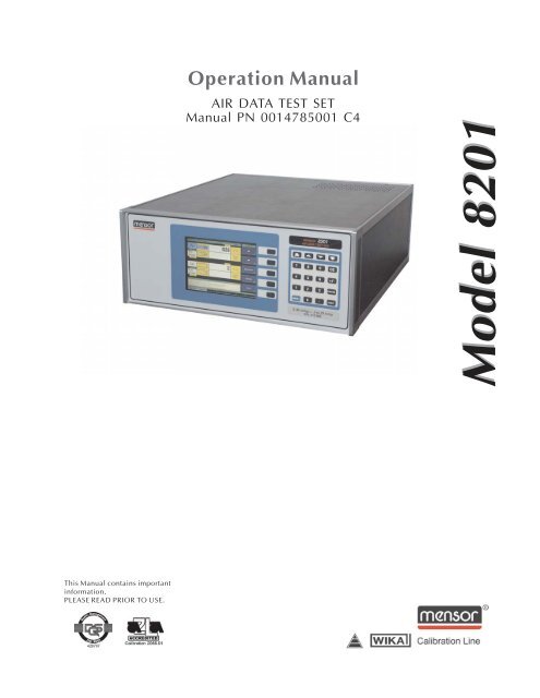
Operation Manual<br />
AIR DATA TEST SET<br />
Manual PN 0014785001 C4<br />
<strong>Model</strong> <strong>8201</strong><br />
<strong>Model</strong> <strong>8201</strong>
PREFACE MODEL <strong>8201</strong> - ADTS<br />
WARRANTY<br />
All products manufactured by <strong>Mensor</strong>® <strong>Corporation</strong> are warranted to be free of defects in workmanship<br />
and materials for a period of one year from the date of shipment. No other express warranty is<br />
given, and no affirmation of Seller, by words or actions, shall constitute a warranty. SELLER<br />
DISCLAIMS ANY IMPLIED WARRANTIES OF MERCHANTABILITY OR FITNESS FOR ANY PARTICU-<br />
LAR PURPOSES WHATSOEVER. If any defect in workmanship or material should develop under<br />
conditions of normal use and service within the warranty period, repairs will be made at no charge<br />
to the original purchaser, upon delivery of the product(s) to the factory, shipping charges prepaid. If<br />
inspection by <strong>Mensor</strong> <strong>Corporation</strong> or its authorized representative reveals that the product was<br />
damaged by accident, alteration, misuse, abuse, faulty installation or other causes beyond the control<br />
of <strong>Mensor</strong> <strong>Corporation</strong>, this warranty does not apply. The judgment of <strong>Mensor</strong> <strong>Corporation</strong> will be<br />
final as to all matters concerning condition of the product, the cause and nature of a defect, and the<br />
necessity or manner of repair. Service, repairs or disassembly of the product in any manner,<br />
performed without specific factory permission, voids this warranty.<br />
MENSOR CORPORATION MAKES NO WARRANTY OF ANY KIND WITH REGARD TO THIS MANUAL,<br />
INCLUDING, BUT NOT LIMITED TO, THE IMPLIED WARRANTIES OF MERCHANTABILITY AND<br />
FITNESS FOR A PARTICULAR PURPOSE. <strong>Mensor</strong> <strong>Corporation</strong> shall not be liable for errors contained<br />
herein or for incidental or consequential damages in connection with the furnishing, performance,<br />
or use of this material.<br />
WARNINGS AND CAUTION NOTES<br />
WARNING: NOT EXPLOSION PROOF!<br />
Installation of this instrument in an area requiring devices rated as intrinsically<br />
safe is not recommended.<br />
WARNING: POSSIBLE INJURY!<br />
The tubing, valves and other apparatus attached to the gauge must be adequate<br />
for the maximum pressure which will be applied, otherwise physical injury to the<br />
operator or bystanders is possible.<br />
CAUTION: USE THE PROPER PRESSURE MEDIUM. USE ONLY CLEAN,<br />
DRY NON-CORROSIVE GASES. THIS INSTRUMENT IS NOT DESIGNED<br />
FOR OXYGEN USE.<br />
CAUTION: ESD PROTECTION REQUIRED. The proper use of grounded<br />
work surfaces and personal wrist straps are required when coming into contact<br />
with exposed circuits (printed circuit boards) to prevent static discharge to<br />
sensitive electronic components.<br />
IMPORTANT NOTICE<br />
Please Note: The product specifications and other information contained in this manual are subject<br />
to change without notice.<br />
<strong>Mensor</strong> <strong>Corporation</strong> has made a concerted effort to provide complete and current information for<br />
the proper use of the equipment. If there are questions regarding this manual or the proper use of<br />
the equipment, contact <strong>Mensor</strong> <strong>Corporation</strong> at:<br />
TEL 1.512.396.4200 WEB SITE www.mensor.com<br />
TEL 1.800.984.4200 (USA only) E-MAIL sales@mensor.com<br />
FAX 1.512.396.1820 tech.support@mensor.com<br />
quality@mensor.com<br />
ii MENSOR® CORP.
MODEL <strong>8201</strong> - ADTS PREFACE<br />
PACKAGING FOR SHIPMENT<br />
If the product must be shipped to a different location or returned to <strong>Mensor</strong> for any reason through<br />
a common carrier it must be packaged properly to minimize the risk of damage.<br />
The recommended method of packing is to place the instrument in a container, surrounded on all<br />
sides with at least four inches of shock attenuation material such as styrofoam peanuts.<br />
TRADEMARKS<br />
<strong>Mensor</strong> is a registered trademark of <strong>Mensor</strong> <strong>Corporation</strong>. All other brand and product names are<br />
trademarks or registered trademarks of their respective companies. The ADTS instrument contains<br />
software licensed from Microsoft <strong>Corporation</strong>.<br />
©2004, <strong>Mensor</strong> Corp. All rights reserved.<br />
SOFTWARE LICENSE AGREEMENT<br />
This product contains intellectual property, i.e., software programs, that are licensed for use by the<br />
end user/customer (hereinafter “end User”).<br />
This is not a sale of such intellectual property.<br />
The end user shall not copy, disassemble or reverse compile the software program.<br />
THE SOFTWARE PROGRAMS ARE PROVIDED TO THE END USER “AS IS” WITHOUT WARRANTY<br />
OF ANY KIND, EITHER EXPRESS OR IMPLIED, INCLUDING, BUT NOT LIMITED TO, WARRANTIES<br />
OF MERCHANTABILITY AND FITNESS FOR A PARTICULAR PURPOSE. THE ENTIRE RISK OF THE<br />
QUALITY AND PERFORMANCE OF THE SOFTWARE PROGRAM IS WITH THE END USER.<br />
MENSOR AND ITS SUPPLIERS SHALL NOT BE HELD TO ANY LIABILITY FOR ANY DAMAGES<br />
SUFFERED OR INCURRED BY THE END USER (INCLUDING, BUT NOT LIMITED TO, GENERAL,<br />
SPECIAL, CONSEQUENTIAL OR INCIDENTAL DAMAGES INCLUDING DAMAGES FOR LOSS OF<br />
BUSINESS PROFITS, BUSINESS INTERRUPTION, LOSS OF BUSINESS INFORMATION AND THE<br />
LIKE), ARISING FROM OR IN CONNECTION WITH THE DELIVERY, USE OR PERFORMANCE OF<br />
THE SOFTWARE PROGRAM.<br />
FCC RADIO FREQUENCY EMISSION NOTICE<br />
This equipment has been tested and found to comply with the limits for a Class A digital device,<br />
pursuant to Part 15 of the FCC Rules. These limits are designed to provide reasonable protection<br />
against harmful interference when the equipment is operated in a commercial environment. This<br />
equipment generates, uses, and can radiate radio frequency energy and, if not installed and used in<br />
accordance with the instruction manual, may cause harmful interference to radio communications.<br />
Operation of this equipment in a residential area is likely to cause harmful interference in which case<br />
the user will be required to correct the interference at his or her own expense.<br />
USE SHIELDED CABLES TO CONNECT EXTERNAL DEVICES TO THIS INSTRUMENT TO MINI-<br />
MIZE RF RADIATION.<br />
MENSOR® CORP. iii
PREFACE MODEL <strong>8201</strong> - ADTS<br />
User's Notes:<br />
iv MENSOR® CORP.
MODEL <strong>8201</strong> - ADTS TABLE OF CONTENTS<br />
TABLE OF CONTENTS<br />
Warranty . . . . . . . . . . . . . . . . . . . . . . . . . . . . . . . . . . . . . . . . ii<br />
Warnings and Caution Notes . . . . . . . . . . . . . . . . . . . . . . . . . . . . . . ii<br />
Please Notice . . . . . . . . . . . . . . . . . . . . . . . . . . . . . . . . . . . . . . ii<br />
Packaging for Shipment . . . . . . . . . . . . . . . . . . . . . . . . . . . . . . . . iii<br />
Trademarks . . . . . . . . . . . . . . . . . . . . . . . . . . . . . . . . . . . . . . iii<br />
Software License Agreement . . . . . . . . . . . . . . . . . . . . . . . . . . . . . . iii<br />
FCC Radio Frequency Emission Notice . . . . . . . . . . . . . . . . . . . . . . . . iii<br />
INTRODUCTION<br />
Did you get Everything? . . . . . . . . . . . . . . . . . . . . . . . . . . . . . . . . . 1-1<br />
Initial Inspection . . . . . . . . . . . . . . . . . . . . . . . . . . . . . . . . . . . . . 1-1<br />
Meet your ADTS . . . . . . . . . . . . . . . . . . . . . . . . . . . . . . . . . . . . . 1-1<br />
Instrument Case . . . . . . . . . . . . . . . . . . . . . . . . . . . . . . . . . . . 1-1<br />
Front Panel . . . . . . . . . . . . . . . . . . . . . . . . . . . . . . . . . . . . . 1-1<br />
Display . . . . . . . . . . . . . . . . . . . . . . . . . . . . . . . . . . . . . . . . 1-2<br />
Main Keypad . . . . . . . . . . . . . . . . . . . . . . . . . . . . . . . . . . . . . 1-4<br />
Rear Panel . . . . . . . . . . . . . . . . . . . . . . . . . . . . . . . . . . . . . . 1-5<br />
Electrical Module . . . . . . . . . . . . . . . . . . . . . . . . . . . . . . . . . . . 1-6<br />
Pneumatic Module . . . . . . . . . . . . . . . . . . . . . . . . . . . . . . . . . . 1-7<br />
Chassis Assembly . . . . . . . . . . . . . . . . . . . . . . . . . . . . . . . . . . 1-8<br />
Power Up! . . . . . . . . . . . . . . . . . . . . . . . . . . . . . . . . . . . . . . . . 1-9<br />
<strong>Mensor</strong> Service Plus . . . . . . . . . . . . . . . . . . . . . . . . . . . . . . . . . . . 1-9<br />
After the Warranty . . . . . . . . . . . . . . . . . . . . . . . . . . . . . . . . . . 1-9<br />
Calibration Services . . . . . . . . . . . . . . . . . . . . . . . . . . . . . . . . . 1-9<br />
Accreditations . . . . . . . . . . . . . . . . . . . . . . . . . . . . . . . . . . . . 1-9<br />
INSTALLATION<br />
Mounting . . . . . . . . . . . . . . . . . . . . . . . . . . . . . . . . . . . . . . . . . 2-1<br />
Pressure Connections . . . . . . . . . . . . . . . . . . . . . . . . . . . . . . . . . . 2-1<br />
SUPPLY Pressure Port . . . . . . . . . . . . . . . . . . . . . . . . . . . . . . . . 2-1<br />
EXHAUST Pressure Ports . . . . . . . . . . . . . . . . . . . . . . . . . . . . . . 2-1<br />
MEASURE/CONTROL Pressure Ports . . . . . . . . . . . . . . . . . . . . . . . . 2-1<br />
Power On . . . . . . . . . . . . . . . . . . . . . . . . . . . . . . . . . . . . . . . . 2-1<br />
LOCAL OPERATION<br />
Keypads . . . . . . . . . . . . . . . . . . . . . . . . . . . . . . . . . . . . . . . . . 3-1<br />
Main Keypad . . . . . . . . . . . . . . . . . . . . . . . . . . . . . . . . . . . . . 3-1<br />
Function Keys . . . . . . . . . . . . . . . . . . . . . . . . . . . . . . . . . . . . 3-1<br />
Local Operation Screens . . . . . . . . . . . . . . . . . . . . . . . . . . . . . . . . . 3-2<br />
The Menu Screen . . . . . . . . . . . . . . . . . . . . . . . . . . . . . . . . . . . 3-3<br />
The Operate Screen . . . . . . . . . . . . . . . . . . . . . . . . . . . . . . . . . 3-4<br />
The Main <strong>Set</strong>up Screen . . . . . . . . . . . . . . . . . . . . . . . . . . . . . . . 3-5<br />
The Instrument <strong>Set</strong>up Screen . . . . . . . . . . . . . . . . . . . . . . . . . . . . 3-6<br />
The Ps Channel <strong>Set</strong>up Screen . . . . . . . . . . . . . . . . . . . . . . . . . . . . 3-7<br />
The Qc and Pt Channel <strong>Set</strong>up Screen . . . . . . . . . . . . . . . . . . . . . . . . 3-8<br />
The Remote Operation <strong>Set</strong>up Screen . . . . . . . . . . . . . . . . . . . . . . . . . 3-9<br />
The Configuration <strong>Set</strong>up Screen . . . . . . . . . . . . . . . . . . . . . . . . . . 3-10<br />
The Opening Status Screen . . . . . . . . . . . . . . . . . . . . . . . . . . . . 3-11<br />
The Sensor Status Screen . . . . . . . . . . . . . . . . . . . . . . . . . . . . . 3-12<br />
The Controller Status Screen . . . . . . . . . . . . . . . . . . . . . . . . . . . 3-13<br />
MENSOR® CORP. v
TABLE OF CONTENTS MODEL <strong>8201</strong> - ADTS<br />
The System Status Screen . . . . . . . . . . . . . . . . . . . . . . . . . . . . . 3-14<br />
The Remote Communication Status Screen . . . . . . . . . . . . . . . . . . . . 3-15<br />
The Error Status Screen . . . . . . . . . . . . . . . . . . . . . . . . . . . . . . 3-16<br />
Vent Mode . . . . . . . . . . . . . . . . . . . . . . . . . . . . . . . . . . . . . . . 3-17<br />
Initial <strong>Set</strong>up . . . . . . . . . . . . . . . . . . . . . . . . . . . . . . . . . . . . 3-17<br />
Vent Operation in <strong>Air</strong> <strong>Data</strong> Mode . . . . . . . . . . . . . . . . . . . . . . . . . . 3-17<br />
Vent Operation in the Pressure Mode . . . . . . . . . . . . . . . . . . . . . . . 3-17<br />
Problems Exiting Slow Vent Mode . . . . . . . . . . . . . . . . . . . . . . . . . 3-17<br />
REMOTE OPERATION<br />
IEEE-488 . . . . . . . . . . . . . . . . . . . . . . . . . . . . . . . . . . . . . . . . 4-1<br />
Command and Query Format . . . . . . . . . . . . . . . . . . . . . . . . . . . . 4-2<br />
ADTS Remote Command <strong>Set</strong> . . . . . . . . . . . . . . . . . . . . . . . . . . . . . 4-2<br />
Command/Query <strong>Set</strong> . . . . . . . . . . . . . . . . . . . . . . . . . . . . . . . . . 4-3<br />
Outform Formats . . . . . . . . . . . . . . . . . . . . . . . . . . . . . . . . . . . 4-5<br />
RS-232 Serial Communication . . . . . . . . . . . . . . . . . . . . . . . . . . . . . 4-6<br />
Cable Requirements . . . . . . . . . . . . . . . . . . . . . . . . . . . . . . . . . 4-6<br />
<strong>Set</strong>up . . . . . . . . . . . . . . . . . . . . . . . . . . . . . . . . . . . . . . . . . 4-6<br />
Parameters . . . . . . . . . . . . . . . . . . . . . . . . . . . . . . . . . . . . . . 4-6<br />
Command Format . . . . . . . . . . . . . . . . . . . . . . . . . . . . . . . . . . 4-6<br />
MAINTENANCE<br />
Beyond the Warranty . . . . . . . . . . . . . . . . . . . . . . . . . . . . . . . . . . 5-1<br />
Self-<strong>Test</strong>s . . . . . . . . . . . . . . . . . . . . . . . . . . . . . . . . . . . . . . . . 5-1<br />
Program Disk Replacement . . . . . . . . . . . . . . . . . . . . . . . . . . . . . . . 5-2<br />
Module Replacement . . . . . . . . . . . . . . . . . . . . . . . . . . . . . . . . . . . 5-2<br />
Electrical Module Circuit Boards . . . . . . . . . . . . . . . . . . . . . . . . . . . 5-2<br />
CMOS Battery Replacement . . . . . . . . . . . . . . . . . . . . . . . . . . . . . 5-2<br />
Spare Parts List . . . . . . . . . . . . . . . . . . . . . . . . . . . . . . . . . . . . . 5-2<br />
CALIBRATION<br />
Environment . . . . . . . . . . . . . . . . . . . . . . . . . . . . . . . . . . . . . . . 6-1<br />
Pressure Standard . . . . . . . . . . . . . . . . . . . . . . . . . . . . . . . . . . . . 6-1<br />
Medium . . . . . . . . . . . . . . . . . . . . . . . . . . . . . . . . . . . . . . . . . 6-1<br />
<strong>Set</strong>up . . . . . . . . . . . . . . . . . . . . . . . . . . . . . . . . . . . . . . . . . . 6-1<br />
Passwords . . . . . . . . . . . . . . . . . . . . . . . . . . . . . . . . . . . . . . . . 6-2<br />
Zero Password . . . . . . . . . . . . . . . . . . . . . . . . . . . . . . . . . . . . 6-2<br />
Master Password . . . . . . . . . . . . . . . . . . . . . . . . . . . . . . . . . . . 6-3<br />
Calibration Sequence . . . . . . . . . . . . . . . . . . . . . . . . . . . . . . . . . . 6-4<br />
Absolute Sensor Calibration (Ps Channel) . . . . . . . . . . . . . . . . . . . . . . 6-4<br />
Differential Sensor Calibration (Qc Channel) . . . . . . . . . . . . . . . . . . . . . 6-5<br />
To Restore Factory Calibrations by Clearing Existing Offsets . . . . . . . . . . . . . . 6-6<br />
SPECIFICATIONS<br />
Measure Specifications . . . . . . . . . . . . . . . . . . . . . . . . . . . . . . . . . 7-1<br />
Control Specifications . . . . . . . . . . . . . . . . . . . . . . . . . . . . . . . . . . 7-1<br />
General Specifications . . . . . . . . . . . . . . . . . . . . . . . . . . . . . . . . . . 7-2<br />
vi MENSOR® CORP.
MODEL <strong>8201</strong> - ADTS TABLE OF CONTENTS<br />
OPTIONS<br />
Relief Valves . . . . . . . . . . . . . . . . . . . . . . . . . . . . . . . . . . . . . . . 8-1<br />
Transport Case . . . . . . . . . . . . . . . . . . . . . . . . . . . . . . . . . . . . . 8-1<br />
Rack Mount Kit . . . . . . . . . . . . . . . . . . . . . . . . . . . . . . . . . . . . . 8-2<br />
APPENDIX<br />
Measurement Units . . . . . . . . . . . . . . . . . . . . . . . . . . . . . . . . . . . 9-2<br />
Conversion Factors, Pressure . . . . . . . . . . . . . . . . . . . . . . . . . . . . . . 9-2<br />
Temperature Conversion . . . . . . . . . . . . . . . . . . . . . . . . . . . . . . . . 9-4<br />
Head Pressure Correction . . . . . . . . . . . . . . . . . . . . . . . . . . . . . . . . 9-5<br />
Gas Density . . . . . . . . . . . . . . . . . . . . . . . . . . . . . . . . . . . . . 9-5<br />
Head Pressure Calculation . . . . . . . . . . . . . . . . . . . . . . . . . . . . . . 9-5<br />
INDEX . . . . . . . . . . . . . . . . . . . . . . . . . . . . . . . . . . . . . . . . 10-1<br />
REFERENCE LIST OF FIGURES<br />
Figure 1.1 - System Block Diagram . . . . . . . . . . . . . . . . . . . . . . . . 1-1<br />
Figure 1.2 - Front Panel . . . . . . . . . . . . . . . . . . . . . . . . . . . . . . 1-1<br />
Figure 1.3 - Screen Elements (Menu Screen) . . . . . . . . . . . . . . . . . . . . 1-2<br />
Figure 1.4 - Menu Screen and Five Function Screens . . . . . . . . . . . . . . . 1-3<br />
Figure 1.5 - Main Keypad . . . . . . . . . . . . . . . . . . . . . . . . . . . . . 1-4<br />
Figure 1.6 - Rear View . . . . . . . . . . . . . . . . . . . . . . . . . . . . . . . 1-5<br />
Figure 1.7 - Electrical Module . . . . . . . . . . . . . . . . . . . . . . . . . . . 1-6<br />
Figure 1.8 - Pneumatic Module . . . . . . . . . . . . . . . . . . . . . . . . . . . 1-7<br />
Figure 1.9 - Pneumatic Schematic . . . . . . . . . . . . . . . . . . . . . . . . . 1-7<br />
Figure 1.10 - Chassis Assembly-Top View . . . . . . . . . . . . . . . . . . . . . 1-8<br />
Figure 2.1 - Menu Screen . . . . . . . . . . . . . . . . . . . . . . . . . . . . . 2-1<br />
Figure 3.1 - Manual Operation Features . . . . . . . . . . . . . . . . . . . . . . 3-1<br />
Figure 3.2 - Function Key Menu Tree . . . . . . . . . . . . . . . . . . . . . . . 3-2<br />
Figure 3.3 - Menu Screen . . . . . . . . . . . . . . . . . . . . . . . . . . . . . 3-3<br />
Figure 3.4 - Operate Screen . . . . . . . . . . . . . . . . . . . . . . . . . . . . 3-4<br />
Figure 3.5 - Main <strong>Set</strong>up Screen . . . . . . . . . . . . . . . . . . . . . . . . . . 3-5<br />
Figure 3.6 - Instrument <strong>Set</strong>up Screen . . . . . . . . . . . . . . . . . . . . . . . 3-6<br />
Figure 3.7 - The Ps Channel <strong>Set</strong>up Screen . . . . . . . . . . . . . . . . . . . . . 3-7<br />
Figure 3.8 - The Qc and Pt Channel <strong>Set</strong>up Screen . . . . . . . . . . . . . . . . . 3-8<br />
Figure 3.9 - The Remote Operation <strong>Set</strong>up Screen . . . . . . . . . . . . . . . . . 3-9<br />
Figure 3.10 - The Configuration <strong>Set</strong>up Screen . . . . . . . . . . . . . . . . . . 3-10<br />
Figure 3.11 - The Opening Status Screen . . . . . . . . . . . . . . . . . . . . 3-11<br />
Figure 3.12 - The Sensor Status Screen . . . . . . . . . . . . . . . . . . . . . 3-12<br />
Figure 3.13 - The Controller Status Screen . . . . . . . . . . . . . . . . . . . 3-13<br />
Figure 3.14 - The System Status Screen . . . . . . . . . . . . . . . . . . . . . 3-14<br />
Figure 3.15 - The Remote Communication Status Screen . . . . . . . . . . . . 3-15<br />
Figure 3.15 - The Error Status Screen . . . . . . . . . . . . . . . . . . . . . . 3-16<br />
Figure 4.1 - RS-232 Cable . . . . . . . . . . . . . . . . . . . . . . . . . . . . . 4-6<br />
Figure 5.1 - The <strong>Test</strong> Screen . . . . . . . . . . . . . . . . . . . . . . . . . . . . 5-1<br />
Figure 5.2 - Chassis, Top View with Covers Removed . . . . . . . . . . . . . . . 5-4<br />
Figure 6.1 - Calibration <strong>Set</strong>up . . . . . . . . . . . . . . . . . . . . . . . . . . . 6-1<br />
Figure 6.2 - Enter/Change Password Screen . . . . . . . . . . . . . . . . . . . . 6-2<br />
Figure 6.3 - Change Passwords Screen . . . . . . . . . . . . . . . . . . . . . . . 6-2<br />
Figure 6.4 - The Zero Calibration Screen . . . . . . . . . . . . . . . . . . . . . 6-3<br />
Figure 6.5 - The Master Calibration Screen . . . . . . . . . . . . . . . . . . . . 6-3<br />
Figure 7.1 - Dimensional Outline . . . . . . . . . . . . . . . . . . . . . . . . . . 7-3<br />
Figure 8.1 - Transport Case . . . . . . . . . . . . . . . . . . . . . . . . . . . . 8-1<br />
MENSOR® CORP. vii
TABLE OF CONTENTS MODEL <strong>8201</strong> - ADTS<br />
Figure 8.2 - Rack Mount Dimensions . . . . . . . . . . . . . . . . . . . . . . . 8-2<br />
Figure 8.3 - Rack Specifications . . . . . . . . . . . . . . . . . . . . . . . . . . 8-3<br />
Figure 8.4 - Slide Specifications . . . . . . . . . . . . . . . . . . . . . . . . . . 8-3<br />
Figure 9.1 - Head Pressure Calculation . . . . . . . . . . . . . . . . . . . . . . 9-5<br />
REFERENCE LIST OF TABLES<br />
Table 2.1 - Supply Pressure Requirement . . . . . . . . . . . . . . . . . . . . . 2-1<br />
Table 3.1 - <strong>Air</strong> <strong>Data</strong> Pressure Terms . . . . . . . . . . . . . . . . . . . . . . . . 3-2<br />
Table 4.1 - Command/Query <strong>Set</strong> . . . . . . . . . . . . . . . . . . . . . . . 4-3 - 4-5<br />
Table 5.1 - Spare Parts . . . . . . . . . . . . . . . . . . . . . . . . . . . . . . . 5-2<br />
Table 7.1 - Material Contacting Pressure Medium . . . . . . . . . . . . . . . . . 7-2<br />
Table 9.1 - Measurement Units . . . . . . . . . . . . . . . . . . . . . . . . . . 9-2<br />
Table 9.2 - Conversion Factors, psi . . . . . . . . . . . . . . . . . . . . . . . . 9-2<br />
Table 9.3 - Conversion Factors, millitorr . . . . . . . . . . . . . . . . . . . . . 9-2<br />
Table 9.4 - Altitude to Pressure Conversion . . . . . . . . . . . . . . . . . . . . 9-3<br />
Table 9.5 - <strong>Air</strong>speed to Pressure Conversion . . . . . . . . . . . . . . . . . . . . 9-3<br />
Table 9.6 - Temperature Conversion . . . . . . . . . . . . . . . . . . . . . . . . 9-4<br />
Table 9.7 - Gas Density . . . . . . . . . . . . . . . . . . . . . . . . . . . . . . 9-5<br />
viii MENSOR® CORP.
MODEL <strong>8201</strong> - ADTS INTRODUCTION<br />
INTRODUCTION<br />
DID YOU GET EVERYTHING?<br />
In addition to this manual you should have:<br />
• <strong>Model</strong> <strong>8201</strong> ADTS<br />
• Power cord<br />
• 1/8 inch NPT fitting adapters<br />
• Any accessories ordered<br />
• Envelope containing a Calibration Certificate<br />
INITIAL INSPECTION<br />
In addition to the many hours of functional testing,<br />
your new instrument was inspected at the factory<br />
for dings, dents and scratches. Please examine it<br />
now for signs of shipping damage. Report any<br />
apparent damage to the carrier immediately.<br />
MEET YOUR ADTS<br />
The <strong>Model</strong> <strong>8201</strong> <strong>Air</strong> <strong>Data</strong> <strong>Test</strong> <strong>Set</strong> (ADTS) is a<br />
special purpose instrument designed to test and<br />
calibrate air data instrumentation for altitude and<br />
airspeed, and their rates of change. An ADTS consists<br />
of a self-contained, computerized, high accuracy,<br />
two channel pressure management system<br />
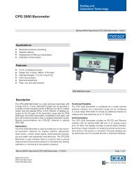
ELECTRICAL<br />
MODULE<br />
PNEUMATICS MODULE<br />
Ps<br />
PNEUMATICS<br />
FRONT PANEL (DISPLAY/ KEYPAD)<br />
Figure 1.1 - System Block Diagram<br />
Qc<br />
PNEUMATICS<br />
integrated into a single, compact unit. The system<br />
is comprised of a front panel assembly, a rear<br />
panel, an electrical module, a pneumatic module,<br />
and a chassis to complete the package (see figure<br />
1.10). The system functions either as a bench-top<br />
or a rack mounted instrument. It can operate in<br />
local mode to accept front panel input, or in remote<br />
mode to communicate with external devices.<br />
Instrument Case<br />
The instrument case is all aluminum construction<br />
with extruded aluminum frame members and vinyl<br />
clad cover and side panels. Front and rear panel<br />
assemblies attach to the case. These are described<br />
separately below.<br />
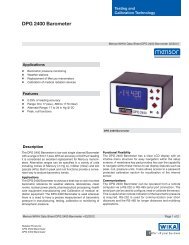
Front Panel<br />
An ADTS front panel (figure 1.2) consists of the<br />
graphic display, a column of five function keys (F1<br />
through F5), and the 20 key main keypad. A label<br />
in the upper right corner shows the model identity,<br />
and another label in the lower right corner shows<br />
the Ps and Pt pressure ranges.<br />
Display<br />
Function<br />
Keys <strong>Model</strong><br />
Keypad<br />
Pressure<br />
Ranges<br />
Figure 1.2 - Front Panel<br />
7 8 9<br />
4 5 6<br />
1 2 3<br />
MENU<br />
MENSOR <strong>8201</strong><br />
AIR DATA TEST SYSTEM<br />
0<br />
0 to 100000 ft<br />
0 to 1000 knots<br />
MENSOR® CORP. 1-1<br />
.<br />
CE<br />
+/-<br />
ENTER<br />
EXEC
INTRODUCTION MODEL <strong>8201</strong> - ADTS<br />
Display<br />
Several different display formats, or screens, are<br />
presented while operating the ADTS. Each screen<br />
is organized into blocks of information, generally<br />
arranged into columns and rows.<br />
When the <strong>8201</strong> is powered up it goes through an<br />
initialization process, then displays the Menu<br />
screen (figure 1.3). This screen is also displayed at<br />
any other time by pressing the blue MENU key on<br />
the main keypad.<br />
Some of the screen elements of the Menu screen<br />
are described in figure 1.3. A header bar across the<br />
top of the screen uses labels to identify the type of<br />
data found directly below the label. Starting at the<br />
left end of the header labels, ‘Channel’ refers to the<br />
Ps channel on top, and Qc (or Pt) channel below<br />
that. The next column, labeled ‘Command’, shows<br />
the last commanded values for Altitude, Altitude<br />
Rate, <strong>Air</strong>speed and <strong>Air</strong>speed Rate. Moving right, the<br />
column under ‘Actual’ displays the currently measured<br />
numerical values for each of the above four<br />
air data parameters. The fourth column, ‘Units’,<br />
displays the measurement units associated with<br />
each of the four values. The far right label, ‘Menu’,<br />
indicates that this is the Menu screen.<br />
A message area below the two channels contains<br />
some screen sensitive Help information. At the very<br />
Ps Channel High &<br />
Low Control Limits<br />
Dark Field indicates<br />
Current Activity<br />
Configured either for<br />
Pressure, or for <strong>Air</strong> <strong>Data</strong><br />
Functional Mode:<br />
MEASURE,<br />
CONTROL,<br />
or VENT<br />
Message Area<br />
Status Bar<br />
Control <strong>Set</strong> Points<br />
Figure 1.3 - Screen Elements (Menu Screen)<br />
bottom a status bar contains labels for the installed<br />
software version number, the current ‘Local’ or<br />
‘Remote’ operating mode, and will show ‘Editing’<br />
and ‘Pending’ messages when new air data values<br />
are being input, but not yet executed.<br />
The five rectangles below the ‘Menu’ label provide<br />
the functional descriptions or cues for each of the<br />
five function keys (F1 through F5). From the Menu<br />
screen any of the five function screens (see figure<br />
1.4) are accessed by using the function keys as<br />
shown in the following schedule:<br />
F1 - OPERATE (Normal operation display)<br />
F2 - SETUP (Change various functional parameters)<br />
F3 - STATUS (Monitor current values and settings)<br />
F4 - CALIBRATE (Change zero or span values, or<br />
change passwords)<br />
F5 - TEST (Perform internal tests on the ADTS)<br />
Section 3 of the manual, Local Operation, explains<br />
the layout and use of the first three of these function<br />
screens; Operate, <strong>Set</strong>up, and Status. The <strong>Test</strong><br />
screen is discussed in the Maintenance section,<br />
and the Calibrate screens are covered in the Calibration<br />
section of the manual.<br />
Current Readings<br />
Column<br />
Header<br />
Labels<br />
Function<br />
Key<br />
Labels<br />
1-2 MENSOR® CORP.
MODEL <strong>8201</strong> - ADTS INTRODUCTION<br />
Menu F1 - Operate<br />
F2 - <strong>Set</strong>up<br />
F4 - Calibrate<br />
Figure 1.4 - Menu Screen and Five Function Screens<br />
F3 - Status<br />
F5 - <strong>Test</strong><br />
MENSOR® CORP. 1-3
INTRODUCTION MODEL <strong>8201</strong> - ADTS<br />
Main Keypad<br />
Twenty single function keys, arranged in five rows<br />
of four columns, make up the keypad (figure 1.5).<br />
In addition to the numbered keys and the decimal<br />
point, there are the following:<br />
1. The Up and Down arrow keys (top-center) are<br />
used to increment and decrement the Control<br />
mode values by a programmed step. To program<br />
the step, enter the step value then press<br />
either [�] or[�].<br />
2. The Up and Down double arrow keys (top-outside)<br />
will step the command point by twice the<br />
step value.<br />
3. The CE key is a backspace to clear numeric<br />
entries, one digit at a time, beginning with the<br />
most recently entered digit. This key is available<br />
only while in the Editing mode as seen on<br />
the bottom status bar.<br />
7 8 9<br />
4 5 6<br />
1 2 3<br />
MENU<br />
0<br />
Figure 1.5 - Main Keypad<br />
4. The +/- polarity key is used to assign polarity<br />
to numeric entries.<br />
5. The ENTER key is used to store a newly edited<br />
value. The new value is immediately reflected<br />
on the operating screen, but does not yet take<br />
effect. This is indicated by the bottom right<br />
hand label showing the ‘Pending’ flag.<br />
6. The EXEC key will execute the pending values<br />
into the system such that the Control mode<br />
will immediately use the commanded numbers.<br />
7. The MENU key immediately returns the Menu<br />
screen (figure 1.3) to the display.<br />
.<br />
CE<br />
+/–<br />
ENTER<br />
1-4 MENSOR® CORP.<br />
EXEC
MODEL <strong>8201</strong> - ADTS INTRODUCTION<br />
Rear Panel<br />
The rear panel (figure 1.6) includes access to the<br />
line-fuse holder, the power cord socket, the system<br />
power switch, a ventilator fan opening, and several<br />
communication connectors. All of these items are<br />
grouped on the electrical module side of the rear<br />
panel.<br />
The pneumatic side exposes the pressure ports for<br />
the two pneumatic channels. This side may also<br />
have additional electrical or pneumatic connectors<br />
to support any installed options.<br />
Pt Ps<br />
Pt<br />
MEASURE/<br />
CONTROL<br />
Pt<br />
SUPPLY<br />
Ps<br />
MEASURE/<br />
CONTROL<br />
Ps<br />
SUPPLY<br />
(INTERNAL CONNECTION)<br />
Pt<br />
EXHAUST<br />
Ps<br />
EXHAUST<br />
Pressure<br />
Ports<br />
Communication<br />
Ports<br />
Power<br />
Switch<br />
Figure 1.6 - Rear View<br />
90-132VAC OR 180-264VAC<br />
47-63 Hz<br />
75VA Max.<br />
FUSE: 250V/1.5A<br />
TYPE T<br />
Power<br />
Connector<br />
Line Fuses<br />
MENSOR® CORP. 1-5
INTRODUCTION MODEL <strong>8201</strong> - ADTS<br />
Electrical Module<br />
The internal electrical module (figure 1.7) consists<br />
of the input power module, a fan, a power supply,<br />
an AT compatible single board computer, a 3.5<br />
inch disk drive and a solid state disk drive. The<br />
solid state disk drive contains the program information<br />
to run the system. Note that the plug-in<br />
printed circuit cards are not necessarily in the<br />
order illustrated.<br />
SBC<br />
Backplane<br />
GPIB Board<br />
PLA Board<br />
PLA Board<br />
(Shown with cover removed)<br />
Figure 1.7 - Electrical Module<br />
Input Power<br />
Module<br />
Power Supply<br />
and Fan<br />
1-6 MENSOR® CORP.
MODEL <strong>8201</strong> - ADTS INTRODUCTION<br />
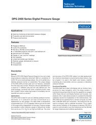
Pneumatic Module<br />
The pneumatic module (figure 1.8) includes two<br />
high performance, low-drift, pressure transducers<br />
which are traceable to NIST as secondary standards.<br />
These transducers are used in conjunction<br />
with two independent, high stability pressure regulators<br />
to produce two precise pressure outputs.<br />
The outputs are commonly referred to as Static<br />
Pressure (Ps) and Total Pressure (Pt). The Ps out-<br />
Ps<br />
Qc<br />
FRONT<br />
*<br />
Ps<br />
CONTROLLER<br />
SEE NOTE 1<br />
Qc<br />
CONTROLLER<br />
L2<br />
L8<br />
Ps<br />
Transducer<br />
Qc<br />
Transducer<br />
put has a range of 1.0 to 32 inHg A and is normally<br />
used to calibrate static pressure transducers. The<br />
Pt output is derived by adding the Qc and Ps<br />
pressures. Qc is a differential pressure with a span<br />
from -0.5 in Hg to 10 inHg, up to -0.5 to 100 inHg,<br />
which is used for airspeed computations. The second<br />
pressure channel can function and display<br />
either the actual Qc data or the derived Pt data.<br />
* See Note 1 of the Pneumatic Schematic, Figure 1.9. REAR<br />
L1<br />
L5<br />
L11<br />
L7<br />
Figure 1.8 - Pneumatic Module<br />
~<br />
35 to 40<br />
inHga<br />
Ps<br />
XDCR<br />
Qc<br />
XDCR<br />
110% of Qc<br />
L3<br />
32 to 35<br />
inHga<br />
10 to 70<br />
inHg G<br />
Ref<br />
L9<br />
FILTER<br />
L4<br />
L10<br />
FILTER<br />
VENT<br />
L12<br />
VENT<br />
NOTES: 1. For single source pressure plug one of the two external SUPPLY<br />
ports, or for independent sources disconnect the internal tube marked<br />
" " which joins the two controllers.<br />
2. Solenoid valves L1 through L12 are 5 vdc, 1.5 w, normally closed.<br />
3. Solenoid valve L6 is omitted.<br />
Figure 1.9 - Pneumatic Schematic<br />
FILTER<br />
FILTER<br />
FILTER<br />
Negative Qc<br />
Protection<br />
FILTER<br />
FILTER<br />
FILTER<br />
Ps<br />
SUPPLY<br />
SEE NOTE 1<br />
Ps<br />
EXHAUST<br />
Ps<br />
OUTPUT<br />
Pt<br />
OUTPUT<br />
Pt<br />
EXHAUST<br />
Pt<br />
SUPPLY<br />
SEE NOTE 1<br />
MENSOR® CORP. 1-7<br />
Ps<br />
Pt
INTRODUCTION MODEL <strong>8201</strong> - ADTS<br />
Chassis Assembly<br />
The chassis assembly acts as the housing for the<br />
system. The layout of the internal system is illustrated<br />
in figure 1.10. The electrical and pneumatic<br />
modules are each self-contained and can be replaced<br />
individually using basic hand tools.<br />
SBC<br />
GPIB Board<br />
PLA Board<br />
PLA Board<br />
REAR<br />
FRONT<br />
The only moving parts in the ADTS are the fan, the<br />
disk drive mechanism, the pneumatic flow controller<br />
diaphragms and valves, and the solenoid valve<br />
plungers. There are no internal user adjustments<br />
or setup switches.<br />
NOTES:<br />
1. The Electrical Module is shown with its cover removed.<br />
2. The plug-in boards may be arranged in a different order than shown.<br />
Figure 1.10 - Chassis Assembly-Top View<br />
Solenoid Driver<br />
Circuit Board<br />
Ps<br />
Transducer<br />
Qc<br />
Transducer<br />
1-8 MENSOR® CORP.
MODEL <strong>8201</strong> - ADTS INTRODUCTION<br />
POWER UP!<br />
You can confirm that your ADTS is operational<br />
right now. Simply apply power to the power connector<br />
on the rear of the instrument, remove any<br />
plastic plugs from the rear panel pressure ports<br />
and turn the power switch ON. The system will go<br />
through a brief initialization process and then the<br />
display should appear similar to the Main Operating<br />
screen shown in figure 1.3.<br />
MENSOR SERVICE PLUS<br />
If you have problems using your ADTS and you<br />
don’t find the answer in your manual, contact<br />
<strong>Mensor</strong> at 1.800.984.4200 (U.S.A. only), or<br />
1.512.396.4200 for personal assistance, or at any<br />
of the on-line addresses listed in the Preface Section<br />
or rear cover page of the manual. We are ready<br />
to help.<br />
After the Warranty<br />
<strong>Mensor</strong>’s concern with the welfare of this instrument<br />
is not limited to the warranty period. We<br />
provide complete repair, calibration and certification<br />
services after the warranty for a nominal fee as<br />
explained in Section 5, Maintenance.<br />
Calibration Services<br />
In addition to servicing our own products <strong>Mensor</strong><br />
can perform a complete pressure calibration service,<br />
up to 20,000 psi, for all of your pressure<br />
instruments. This service meets the requirements<br />
of ANSI/NCSL Z540, and includes a Certificate of<br />
Compliance and Calibration and the record of<br />
traceability to the pressure standards of the National<br />
Institute of Standards and Technology<br />
(NIST).<br />
Accreditations<br />
<strong>Mensor</strong> Corp. is registered to ISO 9001:2008. The<br />
calibration program at <strong>Mensor</strong> is accredited by<br />
A2LA, as complying with both the ISO/IEC<br />
17025:2005 and the ANSI/NCSL Z540-1-1994<br />
standards. All <strong>Mensor</strong> primary standards are<br />
traceable to NIST.<br />
MENSOR® CORP. 1-9
INTRODUCTION MODEL <strong>8201</strong> - ADTS<br />
User's Notes:<br />
1-10 MENSOR® CORP.
MODEL <strong>8201</strong> - ADTS INSTALLATION<br />
INSTALLATION<br />
MOUNTING<br />
The ADTS can be set up on a table-top or it can be<br />
rack-mounted. For rack-mount installation refer to<br />
the rack mount kit in Section 8, Options.<br />
The special sensors used in the ADTS are relatively<br />
insensitive to tilt and vibration. However to further<br />
assure stability and accuracy, excessive motor or<br />
machinery vibration of the mounting surface<br />
should be avoided.<br />
PRESSURE CONNECTIONS<br />
NOTE: When making up the connection<br />
to an o-ring adapter use a back-up<br />
wrench to prevent over-stressing the<br />
threads in the manifold block.<br />
Pressure ports on the rear are female 7/16-20<br />
SAE/MS straight threads per MS16142 and SAE<br />
J514 table 14. They require a tube fitting boss seal<br />
with an o-ring per MS33656. Adhere to the manufacturers<br />
tightening instructions for all fittings and<br />
hoses to minimize errors caused by leaks. <strong>Mensor</strong><br />
provides female 1/8 NPT adapter fittings with the<br />
instrument. Pressure connections can be made to<br />
these adapters with the proper mating hardware.<br />
Use either Loctite Hydraulic Sealant or fresh teflon<br />
tape on the threads of the male pipe fittings. Do not<br />
use sealants on fittings sealed with an o-ring. The<br />
integrity of the seal is particularly important since<br />
even microscopic leaks can cause errors in pressure<br />
measurements. Figure 1.9 is a pneumatic<br />
schematic of the internal plumbing. Requirements<br />
for connecting to the various ports on the ADTS<br />
manifold are provided in the following paragraphs.<br />
SUPPLY Pressure Port<br />
Each channel of the ADTS has its own SUPPLY<br />
port. However, one of these is plugged on the rear<br />
panel since they are connected together inside the<br />
pneumatics module. Connect a source as shown in<br />
table 2.1 to the open SUPPLY.<br />
EXHAUST Pressure Ports<br />
Connect a separate vacuum pump to each of the<br />
two EXHAUST ports. These ports must be evacuated<br />
in order to control at sub-atmospheric pressures.<br />
Although both channels can be connected to<br />
a single vacuum pump, doing so can create cross<br />
channel interference under some conditions, and<br />
is not recommended.<br />
Table 2.1 - Supply Pressure Requirement<br />
~Qc Range ~Pt Range ~Supply Pressure<br />
10 inHg 45 inHgA 20 inHg or 10 psi<br />
20 inHg 55 inHgA 30 inHg or 15 psi<br />
30 inHg 65 inHgA 40 inHg or 20 psi<br />
40 inHg 75 inHgA 60 inHg or 30 psi<br />
50 inHg 85 inHgA 80 inHg or 40 psi<br />
MEASURE/CONTROL Pressure Ports<br />
Devices to be tested are connected to one or two of<br />
the MEASURE/CONTROL ports. In CONTROL<br />
mode these ports can output a precise, stable<br />
(static) pressure, or a pressure which climbs or<br />
falls in an orderly manner (pressure rate).<br />
In MEASURE mode the ADTS will precisely measure<br />
the pressure at the MEASURE/CONTROL port<br />
up to the full scale range of the sensor.<br />
POWER ON<br />
After the pressure connections are secure apply<br />
power to the power connector on the rear of the<br />
instrument and turn the power switch ON. The<br />
instrument will perform an initialization and system<br />
check, then default to MEASURE mode and<br />
display the Menu screen (figure 2.1). The system is<br />
now ready for use, but a warm-up period of at least<br />
45 minutes is advised for greatest accuracy.<br />
Figure 2.1 - Menu Screen<br />
MENSOR® CORP. 2-1
INSTALLATION MODEL <strong>8201</strong> - ADTS<br />
User's Notes:<br />
2-2 MENSOR® CORP.
MODEL <strong>8201</strong> - ADTS LOCAL OPERATION<br />
LOCAL OPERATION<br />
This section describes the procedures for operating<br />
the ADTS from the front panel. The instructions for<br />
operating the instrument remotely from a computer<br />
are covered in the next section. By following<br />
the procedures provided in these two sections, and<br />
Section 6, Calibration, you can expect maximum<br />
accuracy and dependability from your instrument.<br />
In addition to operating and calibration instructions<br />
several self-test routines are built into the<br />
ADTS. Information relating to these tests are presented<br />
in Section 5, Maintenance.<br />
This section of the manual begins with some explanatory<br />
text, followed by several pages of sample<br />
screens. Figure 3.1 illustrates the ADTS features<br />
used during manual operation. Table 3.1 lists<br />
some common terms and labels relating to the<br />
instrument.<br />
KEYPADS<br />
Local operation is accomplished by observing the<br />
data presented in the display, then using the main<br />
keypad and the five function keys to modify the data<br />
or to change to another screen. Throughout this<br />
manual characters enclosed inside square brackets<br />
indicate the associated key. For example, [CE]<br />
indicates the key labeled CE on the main keypad,<br />
and [F4] indicates the fourth key down of the five<br />
function keys.<br />
Display Function Keys<br />
Figure 3.1 - Manual Operation Features<br />
Main Keypad<br />
Thirteen keys on the main keypad are used for<br />
numeric entry (keys [0] through [9], [CE], [+/-], and<br />
[.]. Use [ENTER] to enter the completed value into<br />
the system, however, the entered value does not<br />
take effect until [EXEC] is pressed to execute the<br />
command. Pressing [MENU] at any time will immediately<br />
return the display to the Menu screen.<br />
The up and down arrow keys and the two double<br />
arrow keys at the top of the keypad act as incrementing<br />
or decrementing keys for the controlled<br />
pressure relating to altitude, airspeed, altitude<br />
rate, or airspeed rate. A single arrow steps up or<br />
down by exactly the programmed step value each<br />
time it is pressed, while the double arrow keys act<br />
at twice the step value. To program a step value<br />
enter the value, then press either the [�] or[�]<br />
key.<br />
Function Keys<br />
Notice that the five function keys are always identified<br />
as F1 through F5, but the operation performed<br />
by these keys changes according to which<br />
screen is currently displayed. Each screen includes<br />
its own labels for all five function keys. These labels<br />
appear in the right hand column of each screen.<br />
Figure 3.2 is a menu tree depicting the relationship<br />
of the various function key labels.<br />
7 8 9<br />
4 5 6<br />
1 2 3<br />
MENU<br />
0<br />
.<br />
Main<br />
Keypad<br />
MENSOR® CORP. 3-1<br />
CE<br />
+/-<br />
ENTER<br />
EXEC
LOCAL OPERATION MODEL <strong>8201</strong> - ADTS<br />
LOCAL OPERATION SCREENS<br />
The Menu and Operate screens, and all of the <strong>Set</strong>up<br />
and Status screens may be used during normal<br />
operation of the ADTS. Each of these screens have<br />
sub-screens as depicted by the Menu Tree of figure<br />
3.2. A brief discussion and accompanying illustrations<br />
(figures 3.3 through 3.16) for most of these<br />
screens follow in this section of the manual.<br />
The screens used during calibration are explained<br />
in the Calibration section, and the functions available<br />
for running the built-in diagnostics from the<br />
<strong>Test</strong> screen are discussed in the Maintenance section<br />
of the manual.<br />
MENU<br />
(fig 3.3)<br />
Operate<br />
<strong>Set</strong>up<br />
(fig 3.4) F1<br />
(fig 3.5)<br />
Measure<br />
Control<br />
Vent<br />
F1<br />
F2<br />
F3<br />
F4<br />
F5<br />
F2<br />
Instrument<br />
Sensor<br />
(fig 3.6) F1<br />
(fig 3.12)<br />
Ps<br />
Controller<br />
(fig 3.7) F2<br />
(fig 3.13)<br />
Pt or Qc<br />
System<br />
(fig 3.8) F3<br />
(fig 3.14)<br />
Remote<br />
Remote<br />
(fig 3.9) F4<br />
(fig 3.15)<br />
Configuration<br />
Error<br />
(fig 3.10) F5<br />
(fig 3.16)<br />
Select<br />
Table 3.1 - <strong>Air</strong> <strong>Data</strong> Pressure Terms<br />
The arrangement of the primary data display lists<br />
the static pressure information (Ps and Ps Rate) on<br />
the top half, and either the airspeed data (Qc and<br />
Qc Rate), or the total pressure data (Pt and Pt Rate)<br />
on the bottom half of the data display.<br />
The Ps pressure and Ps Rate relate to the left<br />
channel of the pneumatics module as viewed from<br />
the front of the instrument. The Pt and Qc pressures<br />
and Rates relate to the right pneumatic channel.<br />
Table 3.1 defines the main pressure terms<br />
used by the ADTS.<br />
TERM AIR DATA PARAMETER<br />
Ps Static Pressure Altitude<br />
Ps Rate Static Pressure Rate of Change Altitude Change Rate (Climb or Descend)<br />
Qc Ram Pressure (Pt – Ps) Indicated <strong>Air</strong>speed<br />
Qc Rate <strong>Air</strong>speed Rate of Change Acceleration or deceleration<br />
Pt Total Pressure (Ps + Qc) Static Pressure + Ram Pressure<br />
Pt Rate Total Pressure Rate of Change Leak Rate, etc.<br />
F1<br />
F2<br />
F3<br />
F4<br />
F5<br />
Status Calibrate<br />
<strong>Test</strong><br />
(fig 3.11) F3 (fig 6.2 - 6.5) F4<br />
(fig 5.1)<br />
Select<br />
Figure 3.2 - Function Key Menu Tree<br />
F1<br />
F2<br />
F3<br />
F4<br />
F5<br />
F1<br />
F2<br />
F3<br />
F4<br />
F5<br />
Select<br />
F1<br />
F2<br />
F3<br />
F4<br />
F5<br />
Measure<br />
<strong>Test</strong><br />
Control<br />
<strong>Test</strong><br />
Exhaust<br />
<strong>Test</strong><br />
3-2 MENSOR® CORP.<br />
Supply<br />
<strong>Test</strong><br />
Menu<br />
F5<br />
F1<br />
F2<br />
F3<br />
F4<br />
F5
MODEL <strong>8201</strong> - ADTS LOCAL OPERATION<br />
The ‘Menu’ Screen<br />
The Menu screen in figure 3.3 shows the ADTS<br />
currently configured for air data (Altitude and <strong>Air</strong>speed<br />
readings) with the Ps channel enabled. The<br />
Ps and Qc channels are shown in Measure mode.<br />
The Ps channel pressure control point is set for<br />
1,000 feet, and the control point limits are set to<br />
101,000 ft maximum and -1,870 feet minimum.<br />
The current altitude reading is 585 feet. The setup<br />
control values for the Ps Rate function (second row)<br />
are somewhat different than those seen in the top<br />
(Ps) row. (The actual valves depend on the internal<br />
sensor ranges).<br />
The data for the Qc channel (the lower half of the<br />
data display) is shown in terms of <strong>Air</strong>speed. This<br />
channel can be configured to show either Qc and<br />
Qc Rate, or Pt and Pt Rate as explained later under<br />
the ‘<strong>Set</strong>up’ procedures.<br />
A ‘Help’ message area immediately below the data<br />
display contains some clues as to the available user<br />
actions while in the current screen.<br />
Below the Help window are several ‘Status’ labels.<br />
The left status label always displays the version<br />
Figure 3.3 - The 'Menu' Screen<br />
number for the loaded software. The next window<br />
to the right displays either ‘Local’ for front panel<br />
operation and serial port, or ‘Remote’ when the<br />
ADTS is being controlled through the GPIB communications<br />
port.<br />
When numbers are entered from the main keypad<br />
the far right bottom labels will display ‘Editing’<br />
until [ENTER] is pressed, and ‘Pending’ until<br />
[EXEC] is completed.<br />
From the Menu screen, the only options available<br />
to the user are to press one of the five function keys<br />
to display a different screen, or press any numeric<br />
key to go directly to the Operate screen. If a<br />
number, or a series of numbers are pressed which<br />
are within the control limits established for the<br />
active channel in the Command column, then that<br />
number value appears as the new control command<br />
number.<br />
For normal operations press [F1] to display the<br />
Operate screen, which is discussed next.<br />
MENSOR® CORP. 3-3
LOCAL OPERATION MODEL <strong>8201</strong> - ADTS<br />
The ‘Operate’ Screen<br />
The Operate screen (figure 3.4) is identical to the<br />
Menu screen except that all of the labels in the right<br />
hand column have changed. The right header label<br />
is now ‘Operate’, indicating that this is the main<br />
operating screen. The five F-key labels have<br />
changed to describe different functions.<br />
Ps is the current activity, indicated by the dark field<br />
in the ‘Channel’ column. The channel is displaying<br />
pressure in feet of altitude, but it can show meters<br />
of altitude, or pressure units.<br />
In this and all other screens, an up and down<br />
pointer for [F1] and [F2] will step the active function<br />
highlight up and down in the left (Channel) column.<br />
Press either [F1] or [F2] to step the active function<br />
through Ps, Ps Rate, Qc, and Qc Rate.<br />
The data cells just below the Ps data row display<br />
the Ps Rate information. This is the altitude rate-ofchange<br />
function (rate of climb or descent). Pressure<br />
data for both Ps and Ps Rate are developed in the<br />
left hand pneumatics channel.<br />
The next item down is Qc which is the indicated<br />
airspeed. Below this is the Qc Rate for the rate of<br />
change in airspeed. The lower portion of the screen<br />
that shows Qc and Qc Rate can be configured to<br />
display Pt (total pressure), and Pt Rate (rate of<br />
change of total pressure). The means to accomplish<br />
this change is described later in this section in the<br />
discussion on Instrument <strong>Set</strong>up. The pressure<br />
Figure 3.4 - The 'Operate' Screen<br />
data for the Pt function is the sum of pressure in<br />
the Ps and the Qc transducers.<br />
Press [F4] and both channels immediately go into<br />
‘Control’ mode. The channels change simultaneously<br />
because they are ‘linked’. They can be made<br />
independent, as explained under Instrument <strong>Set</strong>up<br />
(figure 3.6). Press [F5] and both channels switch to<br />
Vent mode. Press [F3] to return both channels to<br />
Measure mode. Initial setup and use of the Vent<br />
mode is explained in detail at the end of this<br />
section.<br />
To edit any of the four air data ‘Command’ values<br />
shown in the display, first use [F1] or [F2] to select<br />
the specific Altitude or <strong>Air</strong>speed function to edit.<br />
Next, press the appropriate number keys to generate<br />
the desired value. Each press of a number key<br />
is reflected in the command value box for the<br />
selected function. If an erroneous number key is<br />
pressed, press [CE] to erase it. [CE] can backspace<br />
through all of the entered numbers until [ENTER]<br />
or [EXEC] is pressed. If an out of limits value is<br />
attempted the system will default to the previous<br />
setting. The allowable upper and lower limits are<br />
shown above and below the current value. These<br />
upper and lower limits are settable within the<br />
<strong>Set</strong>up screens. When a newly entered value is correct,<br />
press [ENTER] for ‘Pending’, or [EXEC] to<br />
complete the entry. With an adequate supply pressure<br />
attached to the system, the new value is the<br />
pressure output that the ADTS will slew to as soon<br />
as [F4]-Control is pressed.<br />
3-4 MENSOR® CORP.
MODEL <strong>8201</strong> - ADTS LOCAL OPERATION<br />
The Main ‘<strong>Set</strong>up’ Screen<br />
This screen (figure 3.5) provides entry into any of<br />
the various setup tables by pressing the appropriate<br />
F-key. Upon selecting a specific setup table the<br />
right hand header label identifies the table, and<br />
[F1] through [F4] will display triangular pointers<br />
which act as cursor control keys. [F5] is a ‘Select’<br />
key. Press this key to set all of the highlighted<br />
values into the system.<br />
The [F1] and [F2] up/down cursor controls operate<br />
only in the left-most column to select the ‘Function’<br />
to be modified. The [F3] and [F4] left/right cursor<br />
keys operate across the ‘<strong>Data</strong>’ columns to highlight<br />
an individual cell within the selected row.<br />
All four cursor controls will wrap around in both<br />
directions. For example, with the highlight resting<br />
on the top ‘Function’ line in any setup table, pressing<br />
the up control, [F1], will cause the cursor to<br />
travel down to the bottom function in the column.<br />
The left and right pointers also wrap across the<br />
data rows in a similar manner.<br />
From the main setup screen select one of the<br />
following:<br />
[F1] - Instrument (figure 3.6): Used to set various<br />
instrument parameters to be displayed, such as:<br />
Figure 3.5 - The Main '<strong>Set</strong>up' Screen<br />
Select either Ps/Qc or Ps/Pt pressure mode or air<br />
data mode for display; set the display contrast level<br />
on a monochrome screen; link or separate the two<br />
displayed channels; select the measurement units<br />
for pressure, altitude, or airspeed; and set several<br />
other instrument variables.<br />
[F2] and [F3] - Ps, Pt/Qc: Each of these channels<br />
has its own setup table screen. The three tables,<br />
which are almost identical, are used to set the<br />
various pneumatic and electronic parameters for<br />
their respective channels.<br />
[F4] - Remote: This setup table assigns the GPIB<br />
address, and the serial port operating parameters.<br />
[F5] - Configuration: Provides the capability to<br />
save, and later, recall up to four different instrument<br />
configurations as defined by the user in the<br />
Instrument and Channels setup tables. This allows<br />
the user to set up four different test situations such<br />
that any one of them can be recalled as the need<br />
arises. Later, the factory defaults can be restored.<br />
Each of the above screens and tables are discussed<br />
next.<br />
MENSOR® CORP. 3-5
LOCAL OPERATION MODEL <strong>8201</strong> - ADTS<br />
The ‘Instrument’ <strong>Set</strong>up Screen<br />
Use this screen (figure 3.6) to set the conditions<br />
listed below for the active channel. Use [F1] and<br />
[F2] cursor keys to move the highlight vertically to<br />
select an item from the Function column. Then use<br />
[F3] and [F4] to move the row highlight horizontally<br />
to the desired <strong>Data</strong> cell. Press [F5] to enable the<br />
selected cell, then select another row (Function) if<br />
desired. All of the cells that are highlighted when<br />
[F5] is last pressed will be enabled.<br />
Display Format: The three choices, shown on the<br />
top <strong>Data</strong> row are: <strong>Air</strong> <strong>Data</strong>; Ps/Pt; or Ps/Qc. Choose<br />
<strong>Air</strong> <strong>Data</strong> to display altitude units (feet, meters, etc)<br />
on the Ps channel, and airspeed (knots, MPH, etc)<br />
units on the Qc channel. Selecting either Ps/Pt, or<br />
Ps/Qc will display pressure units (PSI, kPa, mmHg,<br />
etc) on the respective channels. Note that Ps is<br />
always active (displayed), but the second active<br />
channel might be either Qc or Pt.<br />
To make changes to the Ps channel parameters go<br />
to the Ps Channel <strong>Set</strong>up screen (figure 3.7). To<br />
modify parameters for either the Pt or Qc channel,<br />
select the desired channel for display from here,<br />
then go to the Qc - Pt <strong>Set</strong>up Screen (figure 3.8).<br />
Display Contrast: No effect on a color display.<br />
Channel Link: Either link or separate the two<br />
displayed channels for Measure and Control<br />
modes. Vent mode is always linked.<br />
Figure 3.6 - The 'Instrument' <strong>Set</strong>up Screen<br />
–Qc Protection: Select On to prevent Qc from going<br />
below negative 100 knots. Select Off for no negative<br />
Qc protection.<br />
Local Altitude: Controls the vent rate to this altitude<br />
before venting the system. This should be set<br />
to the local elevation.<br />
Vent Rates: Separate settings are provided for<br />
Altitude and Pressure vent rates. For details, see<br />
the text under ‘Vent Mode’ at the end of this section.<br />
Measurement Units: Separate settings for Pressure,<br />
Rate, Altitude and <strong>Air</strong>speed units. Select one<br />
from each category. (See Mach Units box, below.)<br />
Notice that the Display Format selection determines<br />
whether units of measure are displayed as<br />
air data units or pressure units.<br />
Reading Filter: This is an electronic filter to<br />
smooth out the pressure readings. The more filtering<br />
applied, the less nervous are the displayed<br />
readings.<br />
Back to setup: With the cursor on this function<br />
press either function key [F5], or [ENTER] or<br />
[EXEC] on the main keypad to enable all of the<br />
highlighted settings for the instrument and return<br />
to the main <strong>Set</strong>up screen.<br />
Mach Units: Mach in this instrument<br />
is calculated for subsonic<br />
flight only (< 1.0 Mach).<br />
The following equation is used to<br />
calculate the Mach value:<br />
Mach=<br />
5<br />
Pt<br />
Ps<br />
2/7 -1<br />
Where:<br />
Ps = static pressure in inHg<br />
Pt = total pressure in inHg<br />
3-6 MENSOR® CORP.
MODEL <strong>8201</strong> - ADTS LOCAL OPERATION<br />
The ‘Ps’ Channel <strong>Set</strong>up Screen<br />
Unlike the Pt and Qc channels, the Ps channel is<br />
always active, and these parameters can be<br />
changed at any time. Simply press [MENU], [F2],<br />
[F2], and the screen shown in figure 3.7 will appear.<br />
Notice that there is no highlight showing in the data<br />
cells. For this screen the left and right cursor<br />
controls, [F3] and [F4] are disabled. Use [F1] or<br />
[F2] to select any function in the left column, and<br />
the value in the next column immediately changes<br />
to a ‘?’ prompt. Press the number keys to enter a<br />
new value for the function. Again, if an erroneous<br />
number is entered, press [CE] to clear it. Continue<br />
pressing [CE] to backspace through any previously<br />
entered digits. When the new data value appears to<br />
be correct press [ENTER] on the main keypad to<br />
complete the activity.<br />
The right hand data column lists the units of measure<br />
assigned to each function in this channel. These<br />
units can be changed only in the ‘Instrument’ setup<br />
routine as previously explained; they cannot be<br />
changed in this screen. Values can be changed here<br />
for the following functions:<br />
Figure 3.7 - The 'Ps' Channel <strong>Set</strong>up Screen<br />
Lower Limit: Enter a new value as the low limit for<br />
Altitude, Altitude Rate, Ps pressure, and Ps pressure<br />
Rate. Press [F5] - Select when the displayed<br />
value is correct.<br />
Upper Limit: <strong>Set</strong> the top end limit for the same<br />
four functions, then press [F5].<br />
Stable Window: Enter a new value for the range<br />
within which a controlled output is considered<br />
stable. Individual settings are provided for each of<br />
the four functions; Altitude, Altitude Rate, Ps, and<br />
Ps Rate.<br />
Stable Time: As above, enter the minimum time<br />
that an output pressure must remain within the<br />
window to be considered stable. Separate settings<br />
are available for all four functions.<br />
Notice that the old value will remain in effect if the<br />
cursor is moved away from a function that has been<br />
edited without pressing [F5], [ENTER], or [EXEC].<br />
Also, if the new value is beyond the instrument’s<br />
limits the old value will remain in effect.<br />
MENSOR® CORP. 3-7
LOCAL OPERATION MODEL <strong>8201</strong> - ADTS<br />
The ‘Qc’ and ‘Pt’ Channel <strong>Set</strong>up Screen<br />
The Ps channel (left pneumatics channel) is a dedicated<br />
channel which is always displayed on the<br />
Menu and Operate screens. The second displayed<br />
channel can be either Qc which is the right pneumatics<br />
channel, or Pt which is the sum of the<br />
pressure in the left and right channels.<br />
Whether the Qc or the Pt channel appears in the<br />
Menu, Operate, and in this <strong>Set</strong>up display, is determined<br />
by selection of the ‘Display Format’ in the<br />
Instrument <strong>Set</strong>up table (figure 3.6). The setup<br />
screen is equivalent to the Ps setup screen discussed<br />
on the previous page (figure 3.7), except<br />
substituting ‘<strong>Air</strong>speed’ in place of ‘Altitude’.<br />
<strong>Set</strong> each parameter to its desired value, then press<br />
[F5]-Select.<br />
Figure 3.8 - The 'Qc' and 'Pt' Channel <strong>Set</strong>up Screen<br />
To then change to the other channel (the one which<br />
is not displayed), return to the Instrument <strong>Set</strong>up<br />
table and select the alternate from the Display<br />
Format function. That is, press [MENU], [F2], [F1],<br />
and then either [F3] or [F4] to highlight the other<br />
channel (either Ps/Pt or Ps/Qc). Finally, press Select<br />
[F5], [MENU], [F2], [F3], and the alternate<br />
channel will now appear (figure 3.8) available for<br />
setup changes.<br />
Again, after all parameters are set to their desired<br />
values, press [F5]-Select before exiting this display.<br />
3-8 MENSOR® CORP.
MODEL <strong>8201</strong> - ADTS LOCAL OPERATION<br />
The ‘Remote’ Operation <strong>Set</strong>up Screen<br />
This screen (figure 3.9) is used to set the system<br />
parameters for remote operation. As with the preceding<br />
setup screens, the [F1] and [F2] up/down<br />
pointers operate only on the Function column.<br />
First, select a function, then traverse across the<br />
data row to the desired value, press [F5]-Select,<br />
then step to the next function to modify.<br />
The first five functions pertain to serial bus settings,<br />
while the sixth item sets the GPIB address.<br />
The address is the only menu item available for<br />
GPIB operation.<br />
Figure 3.9 - The 'Remote' Operation <strong>Set</strong>up Screen<br />
When all of the desired values are highlighted, and<br />
the GPIB address is correct, press [F5]-Select.<br />
Finally, either return to setup by selecting that<br />
function on the bottom line of the table entry, or<br />
press [MENU] to return to the main menu screen.<br />
MENSOR® CORP. 3-9
LOCAL OPERATION MODEL <strong>8201</strong> - ADTS<br />
The ‘Configuration’ <strong>Set</strong>up Screen<br />
The ADTS includes the capability to save, and later,<br />
recall up to four different instrument configurations.<br />
These configurations are defined by the user<br />
in the Instrument and Channels setup tables. In<br />
figure 3.10 these four configurations are identified<br />
as CFG1 through CFG4. These are in addition to<br />
the Default setup which is stored in permanent<br />
memory.<br />
Normally, all four of these storage pockets are<br />
loaded with the Default <strong>Set</strong>up when the instrument<br />
leaves the factory. To replace this with a custom<br />
setup:<br />
1. First, make the desired changes to the Instrument,<br />
Ps, Pt and Qc <strong>Set</strong>up tables;<br />
2. Next, display the Configuration <strong>Set</strong>up screen<br />
shown below (figure 3.10);<br />
3. Next, move the Function cursor to Save, and the<br />
data cursor to one of the four CFG# cells;<br />
4. Finally, press [F5]-Select.<br />
The current settings from the Instrument Ps, Pt<br />
and Qc <strong>Set</strong>up tables are now saved as the CFG#<br />
file, to be recalled sometime later.<br />
To load a previously saved custom setup:<br />
1. Move the function cursor to Recall;<br />
2. Move the data cursor to the appropriate CFG#<br />
cell;<br />
3. Press [F5]-Select.<br />
Figure 3.10 - The 'Configuration' <strong>Set</strong>up Screen<br />
The custom setup is now in place, and the ADTS<br />
is ready to run a pre-defined test.<br />
To return the ADTS to the factory default settings<br />
highlight Load in the function column and press<br />
[F5]-Select. The instrument is now loaded with the<br />
initial factory setup.<br />
3-10 MENSOR® CORP.
MODEL <strong>8201</strong> - ADTS LOCAL OPERATION<br />
The Opening ‘Status’ Screen<br />
This screen (figure 3.11) is the entry point to the<br />
five individual status screens. The status screens<br />
display certain data pertaining to:<br />
F1 - Sensor: Both internal pressure transducers;<br />
F2 - Controller: Reserved for future use;<br />
F3 - System: Basic data for the instrument;<br />
F4 - Remote: GPIB and Serial communications;<br />
F5 - Error: Any detected errors.<br />
Figure 3.11 - The Opening 'Status' Screen<br />
These five displays are informational, only, and<br />
require no user interaction. All of the function keys<br />
are disabled in these five screens.<br />
MENSOR® CORP. 3-11
LOCAL OPERATION MODEL <strong>8201</strong> - ADTS<br />
The ‘Sensor’ Status Screen<br />
The Sensor status screen (figure 3.12) displays the<br />
basic information for the two transducers (channels<br />
A and B) that are standard equipment in the<br />
ADTS. There is additional data space to display<br />
information on two external transducers (External<br />
A and External B), but the ADTS does not use<br />
external transducers.<br />
The Minimum Range and Maximum Range are<br />
given in psi units.<br />
Figure 3.12 - The 'Sensor' Status Screen<br />
<strong>Data</strong> displayed for Pressure count and Temperature<br />
count might be useful to a <strong>Mensor</strong> technician<br />
during a telephone troubleshooting session.<br />
No user action is required for this screen; all five<br />
function keys are disabled.<br />
3-12 MENSOR® CORP.
MODEL <strong>8201</strong> - ADTS LOCAL OPERATION<br />
The ‘Controller’ Status Screen<br />
This screen (figure 3.13) is reserved for future use.<br />
No user action is required for this screen; all five<br />
function keys are disabled.<br />
Figure 3.13 - The 'Controller' Status Screen<br />
MENSOR® CORP. 3-13
LOCAL OPERATION MODEL <strong>8201</strong> - ADTS<br />
The ‘System’ Status Screen<br />
The System status screen (figure 3.14) displays the<br />
instrument model number, serial number and date<br />
of manufacture.<br />
No user action is required for this screen; all five<br />
function keys are disabled.<br />
Figure 3.14 - The 'System' Status Screen<br />
3-14 MENSOR® CORP.
MODEL <strong>8201</strong> - ADTS LOCAL OPERATION<br />
The ‘Remote’ Communication Status Screen<br />
The Remote status screen (figure 3.15) is reserved<br />
for future use.<br />
No user action is required for this screen; all five<br />
function keys are disabled.<br />
Figure 3.15 - The 'Remote' Communication Status Screen<br />
MENSOR® CORP. 3-15
LOCAL OPERATION MODEL <strong>8201</strong> - ADTS<br />
The ‘Error’ Status Screen<br />
The Error status screen (figure 3.16) is reserved<br />
for future use.<br />
No user action is required for this screen; all five<br />
function keys are disabled.<br />
Figure 3.16 - The 'Error' Status Screen<br />
3-16 MENSOR® CORP.
MODEL <strong>8201</strong> - ADTS LOCAL OPERATION<br />
VENT MODE<br />
Initial <strong>Set</strong>up<br />
To initially set up the vent mode, go to the Instrument<br />
<strong>Set</strong>up screen (figure 3.6) by pressing [MENU]<br />
[F2] [F1]. <strong>Set</strong> the ‘Local Altitude’ to the approximate<br />
station elevation. Obtain the elevation either<br />
through survey maps or by placing the unit in the<br />
measure mode with the Ps MEASURE/CONTROL<br />
port open to atmosphere and reading the altitude<br />
in feet off of the front panel. This reading will<br />
fluctuate with changing barometric pressure.<br />
<strong>Set</strong> the ‘Altitude Vent Rate’ to a vent rate in feet/<br />
minute or meters/minute that is within the capability<br />
of the devices to be tested. This is the rate at<br />
which the instrument will control the vent process<br />
when in the <strong>Air</strong> <strong>Data</strong> Configuration mode. Six<br />
thousand feet per minute (6,000 f/m) is the default<br />
value for the ADTS.<br />
<strong>Set</strong> the ‘Pressure Vent Rate’ to a vent rate in pressure<br />
units (inHg/minute, psi/minute, mBar/min,<br />
etc.; NOT feet or meters) that is an acceptable rate<br />
for measuring and controlling pressure. The default<br />
value is 30 psi/minute or 61.08 inHg/minute.<br />
Vent Operation in <strong>Air</strong> <strong>Data</strong> Mode<br />
When Vent key [F5] is pressed, the control system<br />
will set the Ps Altitude to the Local Altitude setting<br />
which was entered during the Instrument <strong>Set</strong>up<br />
step, above. It will also set the Ps Rate to the<br />
Altitude Vent Rate setting, set the Qc value to zero,<br />
and leave the Qc rate at its current setting. The<br />
pressure regulator will drive to the setpoints as if<br />
it were in the control mode. This will require an<br />
operational pressure source and vacuum source.<br />
During the process the display will identify the<br />
mode as ‘Slow Vt’ (Slow Vent). When the altitude is<br />
within 10 feet of the setpoint the unit will vent to<br />
atmosphere. The mode will then change to ‘Vent’<br />
and pressure will be released to atmosphere. It is<br />
important that the ‘Local Altitude’ and the ‘Altitude<br />
Vent Rate’ settings are correct to prevent rapid rate<br />
changes from damaging sensitive external devices.<br />
Vent Operation in the Pressure Mode<br />
In the pressure modes of Ps/Qc and Ps/Pt, press<br />
[F5]-Vent and the ADTS will convert the ‘Local<br />
Altitude’ setting to an equivalent pressure, then<br />
apply this to the Ps and Pt channel setpoints, and<br />
apply zero to the Qc pressure channel setpoint. The<br />
pressure rate of change on the Ps and Pt/Qc channels<br />
is set to the ‘Pressure Vent Rate’ setting. The<br />
pressure is controlled at the rate setting until both<br />
channels get close to the setpoints, then the unit<br />
will vent to atmosphere. This mode usually requires<br />
both a pressure source and a vacuum source<br />
to reach the setpoints.<br />
On units with software versions prior to V2.09:<br />
During the process of driving to the setpoints, the<br />
display will indicate a mode of ‘Slow Vt’ (Slow Vent).<br />
When the setpoints are achieved, the mode will<br />
change to ‘Vent’.<br />
Problems Exiting ‘Slow Vent’ Mode<br />
Leaving the unit in the ‘Slow Vent’ mode will consume<br />
gas at an accelerated rate, adding to the wear<br />
and tear on the ADTS, and the connected compressors<br />
and pumps. If the unit will not achieve the vent<br />
setpoints within a reasonable time, and if any<br />
attached devices under test can tolerate a pressure<br />
rate change, reset the control setpoint of one or<br />
both channels to the current reading. This will<br />
force the ADTS into the Vent mode.<br />
To achieve this use the [F1] and [F2] (up and down)<br />
cursor keys to highlight the affected channel, enter<br />
the current reading value using the main keypad,<br />
and finally, press the [ENTER] or [EXEC] key.<br />
MENSOR® CORP. 3-17
LOCAL OPERATION MODEL <strong>8201</strong> - ADTS<br />
User's Notes:<br />
3-18 MENSOR® CORP.
MODEL <strong>8201</strong> - ADTS REMOTE OPERATION<br />
REMOTE OPERATION<br />
The <strong>Air</strong> <strong>Data</strong> <strong>Test</strong> <strong>Set</strong> (ADTS) may be operated from<br />
a remote computer using either the IEEE-488<br />
(GPIB) communication protocol or RS-232 serial<br />
communication. For IEEE-488 operation the host<br />
computer must contain an IEEE-488 Communications<br />
Board.<br />
IEEE-488<br />
Before IEEE-488 communications can be established<br />
between the ADTS and a host, the GPIB<br />
address in the ADTS and the host must be set into<br />
agreement. The ADTS is shipped with the GPIB<br />
address set to 1. To change the address go to the<br />
Remote <strong>Set</strong>up screen by pressing [MENU], [F2],<br />
and [F4] to see the Remote setup table shown in<br />
figure 3.9. Go to the GPIB Address function in that<br />
table and enter a number from 1 to 15, to agree<br />
with the host computer.<br />
The manufacturer of the host IEEE-488 interface<br />
board provides software to allow communication<br />
between the board and various programming languages.<br />
An interactive program for debugging is<br />
usually provided as well. Refer to the board manufacturer’s<br />
documentation for more information.<br />
ADTS IEEE-488 Capability Codes:<br />
SH1 . . . . . . Full source handshake capability<br />
AH1 . . . . . Full acceptor handshake capability<br />
T6 . Talker with serial poll and unaddress if MLA<br />
L4 . . . . . . . . Listener with unaddress if MTA<br />
SR1 . . . . . . . . Full service request capability<br />
RL1 . . Full remote/local capability including LLO<br />
PP0 . . . . . . . . . . . No parallel poll capability<br />
DC1 . . . . . . . . . . Full device clear capability<br />
DT1 . . . . . . . . . Full device trigger capability<br />
C0 . . . . . . . . . . . . . No controller capability<br />
E2 . . . . . . . . . . . . . . . . Tri-state outputs<br />
The ADTS also contains many features of IEEE-<br />
488.2, which is a later version of this protocol.<br />
The ADTS responds to the following IEEE-488<br />
interface functions:<br />
SRQ Service Request<br />
The ADTS asserts service request whenever<br />
an error is encountered. When the bus controller<br />
issues a serial poll the error will be<br />
cleared. If automatic serial polling is available<br />
with your IEEE-488 board, turn this<br />
feature off if you do not want to ignore errors.<br />
(see ERROR? command).<br />
LLO Local Lockout<br />
The front panel keyboard of the ADTS may<br />
be locked by sending LLO or the command<br />
LOCK ON.<br />
GET Group Execute Trigger<br />
When this message is received, the ADTS will<br />
save the current readings until the next time<br />
it is addressed as a talker.<br />
GTL Go To Local<br />
When this message is received, the ADTS will<br />
return to local operation and unlock the<br />
keyboard.<br />
DCL Device Clear<br />
When this message is received, the ADTS will<br />
clear all errors and buffers and remain in the<br />
REMOTE mode.<br />
SDC Selected Device Clear<br />
Responds as DCL.<br />
EOI End or Identify<br />
May be used to terminate a command or<br />
query in the place of or concurrent with the<br />
transmission of the terminating linefeed.<br />
MENSOR® CORP. 4-1
REMOTE OPERATION MODEL <strong>8201</strong> - ADTS<br />
Command and Query Format<br />
All commands (messages sent to the ADTS) and<br />
queries (requests for messages from the ADTS)<br />
follow a common format. The ADTS accepts commands<br />
and queries in the form of ASCII strings.<br />
The strings are divided into two or three fields. All<br />
strings must terminate with a linefeed (, 0a<br />
hex, 10 dec). All fields must be separated with at<br />
least one whitespace character (20 hex or less<br />
except 0a hex). Normally an ASCII space (20 hex,<br />
32 dec) is used for the field separator. Lower case<br />
letters are converted to uppercase by the ADTS and<br />
may be used to improve readability.<br />
Command/Query Field: Unless otherwise specified,<br />
commands are converted to queries by appending<br />
a question mark to the command. Detailed<br />
command and query functions are listed in table<br />
4.1.<br />
<strong>Data</strong> Field: The data field is either an ASCII string<br />
or numeric value. The data field is only used with<br />
commands, not with queries. In the case of multiple<br />
data fields, commas are used to separate the fields.<br />
String or numeric data are acceptable in any of the<br />
following formats:<br />
Example ASCII string data:<br />
ON<br />
OFF<br />
mBar<br />
inHg<br />
Example ASCII numeric data:<br />
1<br />
1.0<br />
-5.678<br />
25.68324e-5<br />
ADTS Remote Command <strong>Set</strong><br />
Definitions:<br />
[White Space]:<br />
any character code
MODEL <strong>8201</strong> - ADTS REMOTE OPERATION<br />
Command/Query <strong>Set</strong><br />
Command <strong>Data</strong><br />
Table 4.1 - Command/Query <strong>Set</strong><br />
Response / Function<br />
? Returns the current output format.<br />
A Makes the A channel active.<br />
A? Returns the A channel reading.<br />
Address 0-30 <strong>Set</strong>s the GPIB Address.<br />
Address? Returns the GPIB Address.<br />
<strong>Air</strong><strong>Data</strong> Changes the control mode to <strong>Air</strong> <strong>Data</strong> control.<br />
<strong>Air</strong><strong>Data</strong>? Return YES or NO.<br />
<strong>Air</strong>mode<br />
Accepts parameters TRUE or INDICTED and changes the airspeed mode<br />
appropriately.<br />
<strong>Air</strong>mode? Returns TRUE or INDICATED.<br />
<strong>Air</strong>temp<br />
<strong>Set</strong>s the Total Temperature (Tt), in degrees C, that is used for the true airspeed<br />
calculation. Limit: ±100 °C.<br />
<strong>Air</strong>temp? Returns the Total Temperature in degrees C.<br />
Ar? Returns the A channel rate.<br />
Ars? Returns the A rate stable indication (YES or NO).<br />
As? Returns the A channel stable indication (YES or NO).<br />
B Makes the B channel active.<br />
B? Returns the B channel reading.<br />
Br? Returns the B channel rate.<br />
Brs? Returns the B rate stable indication (YES or NO).<br />
Bs? Returns the B channel stable indication (YES or NO).<br />
Chan A,B,P3 or Ratio <strong>Set</strong>s the active channel.<br />
Chan? Returns the active channel name.<br />
CheckValve Yes or No Enables or Disables check valve protection.<br />
CheckValve? Returns YES or NO.<br />
Control Active or linked channels placed in Control Mode.<br />
Control? Returns YES if active channel is in Control Mode. NO if otherwise.<br />
Default <strong>Set</strong>s the default values.<br />
DOM? Returns the date of manufacture.<br />
Error? Returns the next error in the error queue.<br />
Filter 0 to 10 <strong>Set</strong>s the corner frequency for the active channel’s measured reading.<br />
Filter? Returns the filter corner frequency.<br />
Id? Returns MENSOR,<strong>8201</strong>,ssssss,v.vv.<br />
Keylock Yes or No Locks or unlocks keyboard.<br />
Keylock? Returns YES or NO.<br />
Linked Yes or No Links modes of both channels if YES, independent if NO.<br />
Linked? Returns YES or NO.<br />
List? Returns a list of valid channel names.<br />
LowerLimit<br />
Value inside<br />
xducr Range<br />
<strong>Set</strong>s the control limit for the active channel.<br />
LowerLimit? Returns the lower control limit for the active channel.<br />
Measure Active or linked channels placed in Measure Mode.<br />
Measure? Returns YES if active channel is in Measure Mode, NO if otherwise.<br />
Outform 1, 2, or 3 <strong>Set</strong>s the output format. Outform 2 is the default.<br />
Outform? Returns the output format.<br />
Pressure Change the control mode to pressure control.<br />
Continued on next page...<br />
MENSOR® CORP. 4-3
REMOTE OPERATION MODEL <strong>8201</strong> - ADTS<br />
Table 4.1 continued...<br />
Command <strong>Data</strong> Response / Function<br />
Pressure? Returns YES or NO.<br />
PressurePt Puts the ADTS in the pressure Ps/Pt mode.<br />
PressurePt? Returns YES if in pressure Ps/Pt mode, No otherwise.<br />
Ps Makes the left channel active.<br />
Ps? Returns the left channel reading.<br />
Pt Makes the right channel active.<br />
Pt? Returns the right channel reading.<br />
Qc Makes the right channel active.<br />
Qc? Returns the right channel reading.<br />
Range? Returns the range of the active channel.<br />
RangeMax? Returns the maximum range of the active channel.<br />
RangeMin? Returns the minimum range of the active channel.<br />
Rateavg <strong>Set</strong>s the number of seconds for the rate filter.<br />
Rateavg? Returns current number of seconds of the filter.<br />
Rfilter 0 to 10 <strong>Set</strong>s the corner frequency for the active channel rate reading.<br />
Rfilter? Returns the rate filter corner frequency.<br />
RLLimit<br />
in sensor<br />
range<br />
<strong>Set</strong>s the lower rate control limit for the active channel.<br />
RLLimit? Returns the lower rate control limit for the active channel.<br />
RULimit<br />
in sensor<br />
range<br />
<strong>Set</strong>s the upper rate control limit for the active channel.<br />
RULimit? Returns the upper rate control limit for the active channel.<br />
Rsetpt<br />
in sensor<br />
range<br />
<strong>Set</strong>s the control rate setpoint for the active channel.<br />
Rsetpt? Returns the control rate setpoint for the active channel.<br />
Rstable? Returns Yes if current channel rate is stable.<br />
RstableTime 0 to 65535 <strong>Set</strong>s the rate stable time to the number of seconds specified.<br />
RstableTime? Returns the rate stable time.<br />
RStableWin<br />
in sensor<br />
range<br />
<strong>Set</strong>s the rate stable window.<br />
RstableWin? Returns the rate stable window.<br />
Runits<br />
Sec, Min, or<br />
Hour<br />
<strong>Set</strong>s the rate time base units.<br />
Runits?<br />
300, 1200,<br />
Returns the rate units.<br />
Sbaud<br />
2400, 4800,<br />
9600, 19200<br />
<strong>Set</strong>s the serial baud.<br />
Sbaud? Returns the serial baud rate.<br />
Sdata 7 or 8 <strong>Set</strong>s the serial data bits.<br />
Sdata? Returns the serial data bits number.<br />
<strong>Set</strong>pt<br />
value inside<br />
limits<br />
<strong>Set</strong>s the control setpoint for the active channel.<br />
<strong>Set</strong>pt? Returns the control setpoint for the active channel.<br />
Span<br />
desired<br />
pressure or ?<br />
<strong>Set</strong>s span to sent pressure or for ?, clears previous value.<br />
RESTRICTION: Must be >50% of range and has a 1% limit.<br />
Span? Returns span scale factor.<br />
Sparity<br />
EVEN,ODD, or<br />
NONE<br />
<strong>Set</strong>s the serial parity.<br />
Continued on next page...<br />
4-4 MENSOR® CORP.
MODEL <strong>8201</strong> - ADTS REMOTE OPERATION<br />
Table 4.1 continued...<br />
Command <strong>Data</strong> Response / Function<br />
Sparity? Returns the serial parity.<br />
Sstop 1 or 2 <strong>Set</strong>s the serial stop bits.<br />
Sstop? Returns the serial stop bits.<br />
Stable? Returns YES if current channel is stable.<br />
StableTime 0 to 65535 <strong>Set</strong>s the stable time to the number of seconds specified.<br />
StableTime? Returns the stable time.<br />
StableWin<br />
in sensor<br />
range<br />
<strong>Set</strong>s the stable window.<br />
StableWin? Returns the stable window.<br />
Standby Active or linked channels placed in Standby Mode.<br />
Standby? Returns YES if active channel is in the Standby Mode, NO if otherwise.<br />
Step<br />
value inside<br />
limits<br />
<strong>Set</strong>s the control step for the active channel.<br />
Step? Returns the control step for the active channel.<br />
Units<br />
psi, inHg,<br />
inH2O, mbar,<br />
kpa, mmhg,<br />
or units code<br />
Outform Formats<br />
The “Outform” command sets the output format<br />
that will be returned by a subsequent outform<br />
query. The formats are:<br />
<strong>Set</strong>s the instrument engineering units.<br />
Units? Returns the instrument units.<br />
UpperLimit<br />
in sensor<br />
range<br />
<strong>Set</strong>s the upper control limit for the active channel.<br />
UpperLimit? Returns the upper control limit for the active channel.<br />
Vent Active or linked channels placed in Vent Mode.<br />
Vent? Returns YES if active channel is in the Vent mode, NO if otherwise.<br />
VentAltRate <strong>Set</strong>s vent rate in air data mode.<br />
VentAltRate? Returns vent rate.<br />
VentPRate <strong>Set</strong>s vent rate in pressure mode.<br />
VentPRate? Returns vent rate in pressure mode.<br />
Zero<br />
desired<br />
pressure or ?<br />
<strong>Set</strong>s zero to sent pressure or for ?, clears previous value.<br />
Zero? Returns zero offset.<br />
Outform Command Outform Query Returns<br />
1 Ps Pressure, Pt Pressure<br />
2 (Default) Ps Pressure, Qc Pressure (Pt-Ps)<br />
3 Ps Pressure, Pt Pressure, Ps Rate, Pt Rate<br />
MENSOR® CORP. 4-5
REMOTE OPERATION MODEL <strong>8201</strong> - ADTS<br />
RS-232 SERIAL COMMUNICATION<br />
The following applies to serial communication capability.<br />
Refer to the GPIB portion at the beginning<br />
of this section for additional information relating<br />
to commands and responses.<br />
The serial communication port allows the <strong>Mensor</strong><br />
instrument to communicate with computers, terminals<br />
and modems (referred to as the host) in<br />
RS-232 interface format. Communicating over the<br />
serial port does NOT disable the front panel keypad.<br />
However, in order to prevent conflicts, avoid<br />
front panel entry of commands while operating<br />
over the bus.<br />
Cable Requirements<br />
RS-232 communications are transmitted over a<br />
three conductor, shielded cable terminated in a<br />
standard DB9S connector on the instrument end,<br />
and usually a similar DB25 connector on the host<br />
end. Figure 4.1 illustrates the proper pin-outs for<br />
the interconnect.<br />
<strong>Set</strong>up<br />
Before putting the RS-232 interface into operation<br />
the various serial parameters must be manually<br />
selected from the appropriate setup screen (either<br />
COMPUTER<br />
2<br />
3<br />
2<br />
3<br />
CONNECTOR<br />
DB9S<br />
1 SHLD<br />
TX<br />
RX<br />
5 SIG. GND<br />
Figure 4.1 - RS-232 Cable<br />
“System <strong>Set</strong>up” or “Remote <strong>Set</strong>up”, depending on<br />
the software level). The serial parameters selected<br />
must match the host. Commands must be sent in<br />
ASCII format and terminated with either a line feed<br />
() or a carriage return (). Commands are<br />
not case sensitive, and both upper and lower case<br />
characters are accepted. Each query returns a<br />
response after processing.<br />
Parameters<br />
Baud rate: Select the baud rate which matches<br />
that of the host. Available rates are from 200 to<br />
19200.<br />
<strong>Data</strong> Bits: Select either 7 or 8.<br />
Stop Bits: Select either 1 or 2.<br />
Serial Parity: Select None, Odd, or Even.<br />
Command Format<br />
The command format for RS-232 commands is the<br />
same as those given for IEEE-488 operation except<br />
that the termination character may be or<br />
.<br />
5<br />
3<br />
2<br />
CONNECTOR<br />
DB9S<br />
4-6 MENSOR® CORP.<br />
<strong>Mensor</strong> <strong>8201</strong>
MODEL <strong>8201</strong> - ADTS MAINTENANCE<br />
MAINTENANCE<br />
The ADTS was designed for maintenance-free operation.<br />
User maintenance is not recommended<br />
beyond replacement of parts listed in the ‘Spare<br />
Parts List’. If you have questions not covered by this<br />
manual, call 1.800.984.4200 (USA only), or<br />
1.512.396.4200 for assistance, or E-MAIL<br />
tech.support@mensor.com.<br />
BEYOND THE WARRANTY<br />
Take advantage of <strong>Mensor</strong>’s expert product care.<br />
<strong>Mensor</strong> <strong>Corporation</strong> provides complete maintenance<br />
and calibration services, available for a<br />
nominal fee. Our service staff is knowledgeable in<br />
the innermost details of all of our instruments. We<br />
maintain units that are in operation in many different<br />
industries and in a variety of applications, and<br />
by users with a wide range of requirements. Many<br />
of these instruments have been in service for over<br />
twenty years, and continue to produce excellent<br />
results. Returning your instrument to <strong>Mensor</strong> for<br />
service benefits you in several ways:<br />
a. Our intimate knowledge of the instrument assures<br />
you that it will receive expert care.<br />
Figure 5.1 - The '<strong>Test</strong>' Screen<br />
b. In many cases we can economically upgrade an<br />
older instrument to the latest enhancements.<br />
c. Servicing our own instruments which are used<br />
in “real world” applications keeps us informed<br />
as to the most frequent services required. We<br />
use this knowledge in our continuing effort to<br />
design better and more robust instruments.<br />
SELF-TESTS<br />
There are four built-in diagnostic tests which can<br />
be run from the <strong>Test</strong> screen shown in figure 5.1.<br />
Each test will return a Pass or Fail indication. To<br />
see the test screen press [MENU], then [F5], then<br />
run any of the following tests:<br />
[F1] - Measure <strong>Test</strong>: Vents the active channel to<br />
atmosphere and tests that the measured pressure<br />
is reasonable.<br />
[F2] - Control <strong>Test</strong>: Opens and closes each of the<br />
four valves in the regulator of the channel and tests<br />
for an appropriate pressure change at each step.<br />
MENSOR® CORP. 5-1
MAINTENANCE MODEL <strong>8201</strong> - ADTS<br />
PROGRAM DISK REPLACEMENT<br />
In order to replace the system program disk, first<br />
remove the power cord from the instrument. Then<br />
remove the rear panel by removing the five screws<br />
holding it to the frame and the four screws near the<br />
pressure ports. The disk drive is located in the<br />
upper center at the rear of the instrument. The disk<br />
is ejected by pressing the eject button.<br />
Push the new disk into the disk slot until it locks<br />
in place. Replace the rear panel and restore the<br />
instrument power. Turning on the instrument will<br />
reboot the ADTS and load the new program.<br />
MODULE REPLACEMENT<br />
To replace an electrical or a pneumatic module<br />
follow these steps:<br />
1. Remove power cord.<br />
2. Remove the top cover by removing the three<br />
screws on the top rear.<br />
3. Remove the pressure fittings from the rear.<br />
4. To remove the pneumatics module, remove<br />
the four screws on the rear panel that screw<br />
into the pressure manifold, and the two screws<br />
under the bottom plate that hold down the<br />
module. Disconnect all the pneumatic module<br />
cables from the electrical module. Then slide<br />
the pneumatic module forward slightly to disengage<br />
it from the key-hole slots in its base,<br />
and lift it out the top of the instrument.<br />
5. To remove the electrical module, remove the<br />
cables to the pneumatic module and the front<br />
panel, and remove the two screws under the<br />
bottom plate that hold down the module. Slide<br />
the module forward slightly to disengage the<br />
key-hole slots in its base, and lift the module<br />
out the top.<br />
6. Reverse the order to replace the module.<br />
Electrical Module Circuit Boards<br />
CAUTION: ESD PROTECTION REQUIRED.<br />
The proper use of grounded work surfaces and<br />
personal wrist straps are required when coming<br />
into contact with exposed circuits (printed circuit<br />
boards) to prevent static discharge damage to<br />
sensitive electronic components.<br />
To gain access to the circuit boards inside the<br />
electrical module without removing the module,<br />
remove the instrument top cover (3 screws), and<br />
the left side panel (2 screws). This allows access to<br />
the ten screws that secure the module cover to the<br />
module chassis; four screws at the top, and 2<br />
screws each at the front, left and right sides. Remove<br />
these ten screws, then lift the module cover<br />
straight up to remove it.<br />
All of the circuit boards in the module are compatible<br />
with IBM AT format Personal Computers<br />
(PC’s). Most are purchased from outside vendors;<br />
they may differ in appearance, and also in position,<br />
from one unit to the next but their functionality<br />
remains the same. The exception is that the PLA<br />
boards are proprietary, designed and assembled<br />
by <strong>Mensor</strong>.<br />
SPARE PARTS LIST<br />
Below is a table showing ADTS spare parts that can<br />
be ordered from <strong>Mensor</strong>.<br />
Table 5.1 – Spare Parts<br />
Part Description<br />
Miscellaneous<br />
Part Number<br />
Manual 0014785001<br />
Fuses 4100111150<br />
Power Cord 4000400002<br />
Rubber Feet 3201300001<br />
Front Panel Assembly 0014940001<br />
Electrical Module 0014812002<br />
GPIB Board 4904000015<br />
Solenoid Driver Board<br />
(modified)<br />
0014835001<br />
PLA Board (specify whether for<br />
Ps or Pt)<br />
0014293001<br />
Power Supply (modified)<br />
Pneumatics<br />
4901000024<br />
LP Regulator Top Cap<br />
Assembly (Std)<br />
0014266002<br />
Fitting Adapter - 7/16-20 to 1/8<br />
NPT Female<br />
4250010020<br />
O-ring seals for 7/16-20<br />
Fitting<br />
4250010021<br />
5-2 MENSOR® CORP.
MODEL <strong>8201</strong> - ADTS MAINTENANCE<br />
SBC<br />
GPIB Board<br />
PLA Board<br />
PLA Board<br />
REAR<br />
FRONT<br />
NOTES:<br />
1. The Electrical Module is shown with its cover removed.<br />
2. The plug-in boards may be arranged in a different order than shown.<br />
Figure 5.2 - Chassis, Top View with Covers Removed<br />
Solenoid Driver<br />
Circuit Board<br />
Ps<br />
Transducer<br />
Qc<br />
Transducer<br />
MENSOR® CORP. 5-3
MAINTENANCE MODEL <strong>8201</strong> - ADTS<br />
User's Notes:<br />
5-4 MENSOR® CORP.
MODEL <strong>8201</strong> - ADTS CALIBRATION<br />
CALIBRATION<br />
The ADTS automatically adjusts the pressure reading<br />
for the effects of temperature and non-linearity<br />
within the calibrated temperature range of 15-<br />
45°C. The process is referred to as dynamic compensation<br />
because each reading is so adjusted<br />
before it is output to the display or to a communication<br />
bus. Thus, a calibrated ADTS operated<br />
within its temperature band, and with proper zero<br />
and span adjustments, will provide accurate pressure<br />
measurements.<br />
The ADTS should have the span verified periodically<br />
on both internal transducers (channels) to<br />
insure their stability. Initially, the recommended<br />
period between calibrations is 180 days, but this<br />
period may be extended as confidence is gained in<br />
the stability of these sensors.<br />
ENVIRONMENT<br />
For maximum accuracy the instrument should be<br />
at rest on a stable platform which is free of excessive<br />
vibration and shock. Then allow the ADTS to<br />
warm up for at least 45 minutes in an ambient<br />
temperature within the compensated range, while<br />
both channels are in the MEASURE mode.<br />
PRESSURE STANDARDS<br />
<strong>Mensor</strong> recommends the use of appropriately accurate<br />
primary pressure standards when calibrating<br />
this instrument. Such standards should be<br />
PRESSURE<br />
SUPPLY<br />
PRESS<br />
PRESSURE<br />
STANDARD<br />
(DWT)<br />
LINE<br />
REGULATOR<br />
VOLUME<br />
CONTROLLER<br />
SHUT-OFF<br />
VALVES<br />
6<br />
DIAPHRAGM TYPE<br />
VACUUM GAUGE<br />
VENT<br />
7<br />
5<br />
METERING<br />
VALVES<br />
PRESSURE<br />
4<br />
sufficient so that when the techniques of the ISO<br />
Guide to the Expression of Uncertainty in Measurement<br />
(GUM) are applied, the instrument meets<br />
its accuracy statements as required by ANSI/NCSL<br />
Z540, or other applicable standards.<br />
MEDIUM<br />
The recommended calibration medium is dry nitrogen<br />
or clean dry instrument air. For pressure<br />
ranges below 20 psia (~40 mHgA) head pressure<br />
height differences between the standard and the<br />
ADTS can cause errors. See ‘Head Pressure Correction’<br />
in the Appendix for further information.<br />
SETUP<br />
Figure 6.1 (Calibration <strong>Set</strong>up) illustrates a typical<br />
setup for either local or remote calibration. In the<br />
figure the additional equipment required for remote<br />
calibration is shown as optional.<br />
In the calibration setup illustration the ‘Pressure<br />
Standard’ is normally a deadweight test instrument,<br />
and the ‘volume controller’ refers to a hand<br />
operated variable-volume pressure vernier device.<br />
A diaphragm type vacuum gauge is recommended<br />
over the gauge tube type of vacuum sensor for<br />
calibrating sub-atmospheric pressures. A vacuum<br />
source with a minimum capacity of 21 liters per<br />
minute is recommended.<br />
VENT<br />
SHUT-OFF<br />
VALVES<br />
VAC NOTE: DISCONNECT WHEN VACUUM<br />
GAUGE RANGE IS EXCEEDED<br />
3<br />
VACUUM<br />
PUMP<br />
2<br />
1<br />
VENT<br />
Figure 6.1 - Calibration <strong>Set</strong>up<br />
Pt Ps<br />
Pt<br />
Ps<br />
MEASURE/ MEASURE/<br />
CONTROL CONTROL<br />
Pt<br />
Ps<br />
SUPPLY SUPPLY<br />
(INTERNAL CONNECTION)<br />
Pt<br />
Ps<br />
EXHAUST EXHAUST<br />
Computer<br />
(Optional)<br />
ADTS<br />
GPIB or<br />
RS-232<br />
MENSOR® CORP. 6-1<br />
90-132VAC OR 180-264VAC<br />
47-63 Hz<br />
75VA Max.<br />
FUSE: 250V/1.5A<br />
TYPE T
CALIBRATION MODEL <strong>8201</strong> - ADTS<br />
PASSWORDS<br />
Before changes can be made to either the zero or<br />
the span values that are recorded in the ADTS a<br />
protective password must be entered via the front<br />
panel keypad. The master password was set at the<br />
factory to 123456.Theuser can replace this<br />
password with a new six digit password as explained<br />
further on. Also, a separate password can<br />
be defined which will authorize adjustments only<br />
to the zero setting. Separate zero and master passwords<br />
allow a facility to provide line personnel with<br />
the zero password for day-to-day zero adjustments,<br />
but limit access to the span adjustment to their<br />
calibration personnel. To assign or change either<br />
level of password requires entry of the current<br />
master password, whatever that is at the time.<br />
Zero Password<br />
In order to establish a zero password:<br />
1. Press [MENU], [F4] to display the password<br />
screen as seen in figure 6.2;<br />
2. Press [F1] to step to the Change Password line;<br />
3. When the ADTS left the factory the master passwordwassetto123456.Enter<br />
these six digits<br />
now, and as each number is pressed an ‘*’ will be<br />
added in the Password cell;<br />
4. With all six digits entered press either [F5],<br />
[ENTER], or [EXEC] to complete the entry, and the<br />
display will change to one similar to figure 6.3;<br />
5. Again, press [F1] to move the highlight to the<br />
‘Enter Zero Password’ function;<br />
6. Assign the new zero password by pressing from<br />
one to six number keys. Each number pressed is<br />
displayed on the screen so that the user can verify<br />
the entry is as desired. Use [CE] to backspace<br />
through erroneous numbers, and then enter the<br />
correction;<br />
NOTE: Store a copy of the new number<br />
where it can be recovered if forgotten.<br />
7. Press [F5], [ENTER], or [EXEC]. The new zero<br />
password is immediately accepted and the ‘?’ symbol<br />
displaces the new numbers in the display.<br />
8. Confirm that the new zero password is valid by<br />
pressing [MENU], [F4], then enter the new password,<br />
and finally, press either [F5], [ENTER], or<br />
[EXEC]. The Ps and Qc zero calibration screen<br />
(figure 6.4) should appear immediately. If it does<br />
not, return to step 1 and repeat the process.<br />
Figure 6.2 - The 'Enter/Change Password' Screen Figure 6.3 - The 'Change Passwords' Screen<br />
6-2 MENSOR® CORP.
MODEL <strong>8201</strong> - ADTS CALIBRATION<br />
Master Password<br />
Use the master password to accomplish any of the<br />
following:<br />
1. Change the master password;<br />
2. Change the zero password;<br />
3. Change the span calibration value;<br />
4. Change the zero offset.<br />
The master password is required for items 1, 2,<br />
and 3, and can be used to achieve item 4 in place<br />
of the zero password.<br />
As previously mentioned, the master password was<br />
set at the factory to 123456.Tochange this to<br />
a new set of six digits:<br />
1. Press [MENU], [F4] to display the password<br />
screen as seen in figure 6.2;<br />
2. Press [F1] to step down to the change password<br />
function;<br />
3. Enter the current master password, and as each<br />
number key is pressed an ‘*’ is added to the password<br />
window;<br />
4. Press either [F5], [ENTER], or [EXEC] to complete<br />
the entry;<br />
5. Enter a series of six numbers which become the<br />
new master password. The numbers are reflected<br />
on the screen as they are pressed.<br />
6. Before proceeding, review the full six digits that<br />
are on the screen to insure that they are correct. A<br />
mistake here could preclude making future calibration<br />
adjustments to the system. Use [CE] to<br />
backspace through the numbers if they need to be<br />
corrected;<br />
CAUTION: The master password is<br />
seldom used, and is easily forgotten.<br />
When making a change write down and<br />
save the new number. If the master<br />
password is lost contact <strong>Mensor</strong>.<br />
7. When satisfied that the new password is correct,<br />
and a printed copy has been filed, press either [F5],<br />
[ENTER], or [EXEC] to complete the entry. The<br />
previous master password is immediately replaced<br />
by the new numbers and the ‘?’ symbol returns to<br />
the display.<br />
8. Confirm that the new master password is valid<br />
by pressing [MENU], [F4], then the new six digit<br />
password, and finally, either [F5], [ENTER], or<br />
[EXEC]. The Ps and Qc Master Calibration screen<br />
(figure 6.5) should appear immediately. If it does<br />
not appear, return to the password entry screen by<br />
pressing [MENU] and [F4], and carefully re-enter<br />
the master password, and [EXEC].<br />
If the master calibration screen still does not appear<br />
contact <strong>Mensor</strong>.<br />
Figure 6.4 - The 'Zero Calibration' Screen Figure 6.5 - The 'Master Calibration' Screen<br />
MENSOR® CORP. 6-3
CALIBRATION MODEL <strong>8201</strong> - ADTS<br />
CALIBRATION SEQUENCE<br />
The ADTS contains an absolute pressure<br />
transducer (Ps) and a differential transducer (Qc).<br />
Zero and span adjustments are available on both<br />
channels. Linearity is preset at the factory and is<br />
not adjustable. Pt has no calibration adjustment<br />
since it is merely derived as the sum of Ps and Qc.<br />
(Ps + Qc = Pt). The Ps and Qc zero and span<br />
adjustments are used to make a linear correction<br />
to the pressure readings of the active transducer<br />
according to the formula:<br />
Reading = ((uncorrected reading) x span correction<br />
) + zero offset<br />
The ADTS automatically applies the correction<br />
value when the calibration function is executed<br />
either locally from the front panel or remotely via<br />
the RS-232 or the GPIB bus.<br />
At times the zero offset is adjusted without doing a<br />
span calibration, but always ensure that the zero is<br />
correct before adjusting the span. To begin a calibration,<br />
connect the ADTS to a calibration setup<br />
similar to figure 6.1. Both pressure channels of the<br />
ADTS should be placed in the measure mode. The<br />
ADTS should be set to read in the Ps and Qc display<br />
mode. (Menu/<strong>Set</strong>up/Instrument and the display<br />
format of Ps/Qc selected.) Open valves 1 and 2 (ref:<br />
figure 6.1) until the calibration is started.<br />
Absolute Sensor Calibration (Ps Channel)<br />
Since the Qc channel is referenced to the Ps channel<br />
pressure, shut-off valve 1 must be left open<br />
throughout the test to apply the pressures to both<br />
the Ps and Qc channels. Close vent valve 2 for now.<br />
To calibrate from the front panel, press [MENU]<br />
and then press [F4]-Calibrate to display the calibration<br />
menu. Enter the zero password to monitor or<br />
change just the zero offset (figure 6.4) or enter the<br />
master password to also monitor or change the<br />
span corrections via the Master Calibration screen<br />
(figure 6.5). The ‘Current’ fields display the current<br />
pressure value in the current engineering units.<br />
The ‘Adjust’ fields display the current zero offsets<br />
and span multipliers. The ‘Units’ fields display the<br />
current units of measure settings.<br />
Absolute sensor (Ps channel) zero offset correction<br />
using a vacuum pump: Evacuate the<br />
transducers to a low absolute pressure that will still<br />
maintain a viscous flow, typically 600 millitorr. At<br />
pressures lower than this the pressure at any particular<br />
point in the system is questionable. Allow<br />
from two to five minutes for the target pressure to<br />
stabilize, then convert the millitorr reading to an<br />
equivalent instrument reading in the active meas-<br />
urement units (600 millitorr = 0.0116 psi or<br />
0.0236 inHg):<br />
PSI value = millitorr value x 0.0000193367<br />
inHg @ 0 C value = millitorr value x 0.0000393701<br />
Table 9.2 in the Appendix lists millitorr conversion<br />
factors.<br />
With the actual pressure of the standard convert to<br />
the units of measure on the ADTS, highlight the Ps<br />
Zero field using the [F1] or [F2] arrow keys, enter<br />
the true pressure using the numeric keys and then<br />
press [F5], [ENTER] or [EXEC] to effect the zero<br />
offset change. Press [MENU] to return to the main<br />
menu, and then press [F1]-Operate to return to the<br />
normal operation.<br />
Or over the bus, send PS to set the channel<br />
to Ps, followed by a linefeed termination character.<br />
Next, send ZERO dd.dddd to enter the desired<br />
zero pressure, where dd.dddd is the true pressure<br />
in the current engineering units, followed by a<br />
linefeed termination character.<br />
Absolute sensor (Ps channel) zero offset correction<br />
using a barometric standard: An alternate<br />
approach to correcting the zero offset in the<br />
transducer is to use a high quality barometric<br />
reference. This approach is applicable when accurate<br />
vacuum standards are not available, a method<br />
of maintaining viscous flow of the gas media are not<br />
available and span corrections are not necessary<br />
or have already been made. It also has an advantage<br />
of having a known good calibration point within the<br />
more commonly used range of an altimeter or air<br />
data computer.<br />
For this method the barometric reference should<br />
have an accuracy of 0.01% of reading or better. To<br />
begin, vent both the Ps port and the barometric<br />
reference to atmosphere. From the front panel of<br />
the ADTS, press [MENU], [F4]-Calibrate to display<br />
the calibration menu. Enter the zero password or<br />
the master password to enable changes to the<br />
calibration (figure 6.4 or 6.5). The ‘Current’ fields<br />
display the current pressure values in the current<br />
engineering units. The ‘Adjust’ fields display the<br />
current zero offsets and span multipliers. The<br />
‘Units’ fields display the current units of measure.<br />
Press the [F1] or [F2] cursor keys to highlight the<br />
Ps Zero field. Use the main keypad to enter the true<br />
pressure from the barometer, then press [F5],<br />
[ENTER] or [EXEC] to effect the zero offset change.<br />
Press [MENU] to return to the main menu, and then<br />
6-4 MENSOR® CORP.
MODEL <strong>8201</strong> - ADTS CALIBRATION<br />
press [F1]-Operate to return to the normal operation.<br />
Or over the bus, send PS to set the active<br />
channel to Ps followed by a linefeed termination<br />
character.<br />
Next, send ZERO dd.ddddto enter the desired<br />
zero pressure, where dd.dddd is the true pressure<br />
in the current engineering units followed by a linefeed<br />
termination character.<br />
Absolute sensor (Ps channel) span correction:<br />
After the zero offset has been checked and corrected<br />
if necessary, the calibration can be checked<br />
at span or a number of pressure points from zero<br />
to full scale. If recalibration is needed, press<br />
[MENU], [F4]-Calibrate to display the calibration<br />
menu. Enter the master password to monitor or<br />
change the span corrections via the Master Calibration<br />
screen (figure 6.5). The ‘Current’ fields display<br />
the current pressure values in the current engineering<br />
units. The ‘Adjust’ fields display the current<br />
zero offsets and span multipliers. The ‘Units’ fields<br />
display the current units of measure.<br />
Apply a pressure of at least 50 percent of full scale<br />
or higher. To minimize errors, bring this pressure<br />
as close to the full scale as practical, rather than at<br />
mid scale. If a calibration setup configuration similar<br />
to figure 6.1 is used, close vent valves 2, 3 and<br />
7, and open shut-off valve 1. Apply pressure to the<br />
pressure supply line and a vacuum to the vacuum<br />
line. Use metering valves 4 and 5 to adjust the<br />
pressure to the approximate target pressure, and<br />
then use the volume controller to fine tune the<br />
reading to float the DWT.<br />
Convert the actual pressure of the standard to the<br />
units of measure of the ADTS. Press cursor key [F1]<br />
or [F2] to highlight the Ps Span field, enter the true<br />
pressure using the numeric keys, and then press<br />
[F5], [ENTER] or [EXEC] to effect the span multiplier<br />
correction. Press [MENU] to return to the<br />
main menu, then press [F1]-Operate to return to<br />
the normal operation.<br />
To do this over the bus, send, send PS to set<br />
the channel to Ps followed by a linefeed termination<br />
character.<br />
Send SPAN dd.dddd to enter the desired zero<br />
pressure, where dd.dddd is the true pressure from<br />
the standard in the current engineering units followed<br />
by a linefeed terminator.<br />
Span corrections can only be made between 50 and<br />
100 percent of span and the maximum allowed<br />
change is plus or minus 10 percent of the<br />
transducer range.<br />
Differential Sensor Calibration (Qc Channel)<br />
Since the Qc channel is referenced to the Ps channel<br />
pressure, shut-off valve 1 must be closed and<br />
vent valve 2 should be left open throughout the test.<br />
To calibrate from the front panel, press [MENU],<br />
then [F4]-Calibrate to display the calibration menu.<br />
Enter the zero password to monitor or change just<br />
the zero offset (figure 6.4) or enter the master<br />
password to monitor or change span, or both zero<br />
and span correction via the Master Calibration<br />
screen (figure 6.5). The ‘Current’ fields display the<br />
current pressure values in the current engineering<br />
units. The ‘Adjust’ fields display the current zero<br />
offsets and span multipliers. The ‘Units’ fields display<br />
the current units of measure.<br />
Differential sensor (Qc channel) zero offset correction:<br />
The simplest way to set the zero offset on<br />
the Qc differential sensor is to vent both the pressure<br />
port (Pt Measure/Control) and its reference<br />
port (Ps Measure/Control) on the ADTS. Next,<br />
press [F1] or [F2] cursor key to highlight the Qc<br />
Zero field, then enter the true pressure (0.000)<br />
from the main keypad, and finally press [F5], [EN-<br />
TER] or [EXEC] to effect the zero offset change.<br />
Press the [MENU] key to return to the main menu,<br />
and then press [F1]-Operate to return to the normal<br />
operation.<br />
To do this over the bus, send QC to set the<br />
channel to Qc, followed by a linefeed termination<br />
character.<br />
Send ZERO 00.0000 to enter the desired zero<br />
pressure, where dd.dddd is the true pressure in<br />
the current engineering units, followed by a linefeed<br />
termination character.<br />
Differential sensor (Qc channel) span correction:<br />
After the zero offset has been checked and<br />
corrected if necessary, the calibration can be<br />
checked at span or a number of pressure points<br />
from zero to full scale. If recalibration is needed,<br />
press [MENU] and then [F4]-Calibrate to display<br />
the calibration menu. Enter the master password<br />
to monitor or change the span corrections via the<br />
Master Calibration screen (figure 6.5). The ‘Current’<br />
fields display the current pressure values in<br />
the current engineering units. The ‘Adjust’ fields<br />
display the current zero offsets and span multipliers.<br />
The ‘Units’ fields display the current units of<br />
measure.<br />
MENSOR® CORP. 6-5
CALIBRATION MODEL <strong>8201</strong> - ADTS<br />
Apply a pressure of at least 50 percent of full scale<br />
or higher. To minimize errors, bring this pressure<br />
as close to the full scale as practical, rather than at<br />
mid scale. If a calibration setup configuration similar<br />
to figure 6.1 is used, close shut-off valve 1, and<br />
vent valves 3 and 7, and open vent valve 2. Apply<br />
pressure on the pressure supply line. Use metering<br />
valves 4 and 5 to adjust the pressure to approximately<br />
the target pressure, and then use the volume<br />
controller to fine tune the reading to float the DWT.<br />
Convert the actual pressure of the standard to the<br />
units of measure on the ADTS. Press cursor [F1]<br />
or [F2] to highlight the Qc Span field, enter the true<br />
pressure using the numeric keys, and then press<br />
[F5], [ENTER] or [EXEC] to effect the span multiplier<br />
correction. Press [MENU] to return to the<br />
main menu, then press [F1]-Operate to return to<br />
the normal operation.<br />
To do this over the bus, send QC to set the<br />
channel to Qc, followed by a linefeed termination<br />
character.<br />
Send SPAN dd.dddd to enter the desired zero<br />
pressure, where dd.dddd is the true pressure from<br />
the standard in the current engineering units, followed<br />
by a linefeed termination character.<br />
Span corrections can only be made between 50 and<br />
100 percent of span and the maximum allowed<br />
change is plus or minus 10 percent of the<br />
transducer range.<br />
To Restore Factory Calibrations by Clearing<br />
Existing Offsets<br />
To return a pressure channel’s calibration to the<br />
factory setting, from the front panel, press [MENU],<br />
[F4]-Calibrate to display the calibration menu. Enter<br />
the zero password to change just the zero offset<br />
(figure 6.4) or enter the master password to monitor<br />
or change both zero or span corrections via the<br />
Master Calibration screen (figure 6.5). The ‘Current’<br />
fields display the current pressure values in<br />
the current engineering units. The ‘Adjust’ fields<br />
display the current zero offsets and span multipliers.<br />
The ‘Units’ fields display the current units of<br />
measure. With the appropriate field highlighted (Ps<br />
Zero, Ps Span, Qc Zero, Qc Span) and a ‘?’ showing<br />
in the ‘Desired’ field, press [F5] or [ENTER]. Press<br />
[MENU] to return to the main menu, and then press<br />
[F1]-Operate to return to the normal operation.<br />
6-6 MENSOR® CORP.
MODEL <strong>8201</strong> - ADTS SPECIFICATIONS<br />
SPECIFICATIONS<br />
Accuracy specifications presented herein are obtained<br />
by comparison with primary standards<br />
traceable to the National Institute of Standards and<br />
Technology (NIST). These specifications are obtained<br />
in accordance with the ISO Guide to the<br />
Expression of Uncertainty in Measurement<br />
(GUM). <strong>Mensor</strong> also adheres to ANSI/NCSL Z540.<br />
If there is an exception to the requirements and<br />
recommendations of Z540 during a calibration the<br />
exception is noted on the individual calibration<br />
certificate.<br />
<strong>Mensor</strong> reserves the right to change these specifications<br />
without notice.<br />
MEASURE SPECIFICATIONS<br />
Accuracy<br />
Ps: 0.010% FS pressure.<br />
Qc: 0.010% FS pressure referenced to sea level.<br />
Additional error
SPECIFICATIONS MODEL <strong>8201</strong> - ADTS<br />
Control Offset (Ps and Qc channels)<br />
MODEL <strong>8201</strong> - ADTS SPECIFICATIONS<br />
5.25"<br />
(13.34 cm)<br />
.86"<br />
(2.18 cm)<br />
* 6.97"<br />
(17.70 cm)<br />
FRONT VIEW<br />
17.05" (43.31 cm)<br />
* 19.00" (48.26 cm)<br />
* Overall width with Rack Mount Flanges attached.<br />
SIDE VIEW<br />
20.0" (50.80 cm)<br />
* Add 0.40 inches (1.02 cm) to height with feet attached.<br />
Figure 7.1 - Dimensional Outline<br />
7 8 9<br />
4 5 6<br />
1 2 3<br />
MENU<br />
MENSOR <strong>8201</strong><br />
AIR DATA TEST SYSTEM<br />
0<br />
0 to 100000 ft<br />
0 to 1000 knots<br />
MENSOR® CORP. 7-3<br />
.<br />
CE<br />
+/-<br />
ENTER<br />
EXEC
SPECIFICATIONS MODEL <strong>8201</strong> - ADTS<br />
User's Notes:<br />
7-4 MENSOR® CORP.
MODEL <strong>8201</strong> - ADTS OPTIONS<br />
OPTIONS<br />
This section lists options available for the ADTS.<br />
Users might consider letting the factory install a<br />
special feature not listed here. <strong>Mensor</strong> welcomes<br />
the opportunity to quote on such requests. The cost<br />
of adding an enhancement frequently will amortize<br />
itself in a very short time because of improved<br />
process efficiency.<br />
RELIEF VALVES<br />
There are several types of relief valves available:<br />
� One-way differential<br />
� Two-way differential<br />
� One-way absolute<br />
� One-way absolute with vacuum gauge tube<br />
Relief valves are available for pressure ranges from<br />
0.5 psi to 1020 psi. Over time, contaminants in the<br />
system may enter the valves and prevent proper<br />
operations. Servicing the valves by the user is not<br />
recommended.<br />
Retractable Handle<br />
Wheels<br />
Figure 8.1 - Transport Case<br />
TRANSPORT CASE (PN 0011159001)<br />
A wheeled Transport Case is available suitable for<br />
moving the ADTS between sites, or as an air-freight<br />
(or other) shipping container. The case is constructed<br />
of a high impact plastic with a black<br />
exterior. It includes two keys, locks, a piano hinge,<br />
an anodized interlocking tongue and groove opening,<br />
various nickel-chrome and stainless steel fixtures,<br />
a vinyl satchel style handle and a retractable<br />
pull-out handle. The interior is filled with high<br />
density polyurethane foam with a die-cut cavity to<br />
cradle the instrument with fitting adapters in place,<br />
and an additional cavity to store related accessories.<br />
Rugged and weather resistant, the case makes<br />
an attractive, practical shipping and moving container.<br />
The case weighs approximately 29 pounds<br />
(13.15 kg) unloaded, and can support a load of up<br />
to 150 pounds (68.04 kg). Nominal dimensions are<br />
15 inches by 24 inches by 26 inches (38.10 cm x<br />
60.96 cm x 66.04). (See figure 8.1.)<br />
MENSOR® CORP. 8-1
OPTIONS MODEL <strong>8201</strong> - ADTS<br />
RACK MOUNT KIT (PN 0012425004)<br />
The ADTS is easily mounted into a 7 inch opening<br />
of a 19 inch wide rack. The rack used should satisfy<br />
the dimensional requirements shown below. It<br />
should be free of vibration and excessive heat, as<br />
noted below.<br />
Install the chassis slide, being sure to allow the<br />
proper spacing above and below the ADTS. An<br />
ADTS with the rack mount option is then installed<br />
from the front of the rack. Before installing the<br />
ADTS, remove the four feet from the bottom of the<br />
instrument. Slide the ADTS all the way into position<br />
and secure the instrument to the rack before<br />
connecting power and pneumatic lines to the rear<br />
panel.<br />
6.97"<br />
(17.70 cm)<br />
5.25"<br />
(12.34 cm)<br />
.86"<br />
(2.18 cm)<br />
Instrument<br />
Slide Member<br />
2.30"<br />
(5.84 cm)<br />
After all equipment is installed, check to see that<br />
the temperature inside the rack does not exceed<br />
38°C. If it does, additional rack spacing and/or<br />
ventilation must be considered.<br />
Front View<br />
17.05" (43.31 cm)<br />
* 19.00" (48.26 cm)<br />
* Overall width with Rack Mount Flanges attached.<br />
Side View<br />
20.00" (50.80 cm)<br />
Add 0.40 inches (1.02 cm) to height with feet attached.<br />
Figure 8.2 - Rack Mount Dimensions<br />
CAUTION: Motors or vibration devices<br />
should be mounted so as to minimize<br />
the vibrations at the instrument!<br />
7 8 9<br />
4 5 6<br />
1 2 3<br />
MENU<br />
MENSOR <strong>8201</strong><br />
AIR DATA TEST SYSTEM<br />
0<br />
0 to 100000 ft<br />
0 to 1000 knots<br />
8-2 MENSOR® CORP.<br />
.<br />
CE<br />
+/-<br />
ENTER<br />
EXEC
MODEL <strong>8201</strong> - ADTS OPTIONS<br />
Rack with standard retma<br />
mounting hole pattern<br />
Vertical mounting rails<br />
Countersink 4 holes on<br />
front for #10 Flat Head<br />
screws<br />
5/8" (1.59 cm)<br />
slide member<br />
mounting holes<br />
Rack rear vertical<br />
#10-32 x 1/2"<br />
Pan Head<br />
(2 per slide)<br />
Slide member.<br />
Mates with member<br />
attached to the<br />
<strong>Mensor</strong> Instrument<br />
19" (48.26 cm)<br />
Rack width<br />
7" (17.78 cm) high<br />
instrument opening<br />
VENTILATION:<br />
Provide 1.75 inches (one retma<br />
space, 4.45 cm) above and below<br />
the instrument inside the rack.<br />
Figure 8.3 - Rack Specifications<br />
#10-32 x 1/2"<br />
Pan Head<br />
(2 places)<br />
Slide depth 22" to 25"<br />
(55.88 cm to 63.50 cm)<br />
with bracket provided<br />
Figure 8.4 - Slide Specifications<br />
6-31/32" (17.70 cm)<br />
2" (5.08 cm)<br />
Threaded Retaining Plate<br />
Rack front vertical<br />
#10-32 x 1/2"<br />
Flat Head<br />
(2 per slide)<br />
Pin on inner slide<br />
must be down<br />
MENSOR® CORP. 8-3
OPTIONS MODEL <strong>8201</strong> - ADTS<br />
User's Notes:<br />
8-4 MENSOR® CORP.
MODEL <strong>8201</strong> - ADTS APPENDIX<br />
APPENDIX<br />
TABLE OF CONTENTS<br />
Measurement Units (Table 9.1) . . . . . . . . . . . . . . . 9-2<br />
Pressure Conversion Tables . . . . . . . . . . . . . . . . . 9-2<br />
Conversion Factors, Psi (Table 9.2) . . . . . . . . . . . 9-2<br />
Conversion Factors, Millitorr (Table 9.3) . . . . . . . . 9-2<br />
Altitude to Pressure Conversion (Table 9.4) . . . . . . . 9-3<br />
<strong>Air</strong>speed to Pressure Conversion (Table 9.5) . . . . . . 9-3<br />
Temperature Conversion (Table 9.6) . . . . . . . . . . . . 9-4<br />
Head Pressure Correction<br />
Gas Density (Table 9.7) . . . . . . . . . . . . . . . . . 9-5<br />
Head Pressure Calculation (Figure 9.1) . . . . . . . . . 9-5<br />
MENSOR® CORP. 9-1
APPENDIX MODEL <strong>8201</strong> - ADTS<br />
MEASUREMENT UNITS (Number)<br />
The unitno command selects the measurement units to be output on the bus and the display. The<br />
syntax for the unitno command is UNITS N where N is a number from the ‘Unitno’ column in the<br />
following table.<br />
Table 9.1 – Measurement Units<br />
Unitno Units Output Format<br />
1 pounds per square inch PSI<br />
2 inches of mercury @ 0°C INHG @ 0C<br />
4 inches of water @ 4°C INH2O@ 4C<br />
15 millibar MBAR<br />
19 millimeters of mercury @ 0°C MMHG @ 0C<br />
22 kilopascals KPA<br />
PRESSURE CONVERSION TABLES<br />
Table 9.2 – Conversion Factors, psi<br />
Units Pressure Unit To convert from Psi To convert to Psi<br />
1 PSI 1 1<br />
2 INHG @ 0C 2.03603 0.491152<br />
4 INH2O @ 4C 27.6807 0.0361262<br />
15 MBAR 68.94757 0.01450377<br />
19 MMHG @ 0C 51.7150733 0.0193367<br />
22 KPA 6.894757 0.1450377<br />
Table 9.3 – Conversion Factors, millitorr<br />
Units Pressure Unit To convert from Millitorr To convert to Millitorr<br />
1 PSI 0.0000193367 51715.1<br />
2 INHG @ 0C 0.0000393701 25400.0<br />
4 INH2O @4C 0.000535253 1868.27<br />
15 MBAR 0.00133322 750.064<br />
19 MMHG @ 0C 0.001 1000.00<br />
22 KPA 0.000133322 7500.64<br />
9-2 MENSOR® CORP.
MODEL <strong>8201</strong> - ADTS APPENDIX<br />
Table 9.4 – Altitude to Pressure Conversion<br />
Altitude Ps Pressure<br />
Feet Meters inHgA mmHg Millibars<br />
-3,000 -914 33.311 846.09 1,128.03<br />
-2,000 -610 32.148 816.56 1,088.66<br />
-1,000 -305 31.018 787.87 1,050.41<br />
0 0 29.921 760.00 1,013.25<br />
1,000 305 28.856 732.94 977.17<br />
2,000 610 27.821 706.66 942.13<br />
3,000 914 26.817 681.15 908.12<br />
4,000 1,219 25.842 656.38 875.10<br />
5,000 1,524 24.896 632.36 843.07<br />
6,000 1,829 23.978 609.05 812.00<br />
7,000 2,134 23.088 586.44 781.85<br />
8,000 2,438 22.225 564.51 752.62<br />
9,000 2,743 21.388 543.26 724.28<br />
10,000 3,048 20.577 522.66 696.82<br />
12,000 3,658 19.029 483.35 644.41<br />
14,000 4,267 17.577 446.47 595.24<br />
16,000 4,877 16.216 411.90 549.15<br />
18,000 5,486 14.942 379.53 506.00<br />
20,000 6,096 13.750 349.25 465.63<br />
22,000 6,706 12.636 320.96 427.91<br />
24,000 7,315 11.597 294.56 392.71<br />
26,000 7,925 10.627 269.94 359.89<br />
28,000 8,534 9.725 247.01 329.32<br />
30,000 9,144 8.885 225.69 300.90<br />
32,000 9,754 8.106 205.88 274.49<br />
34,000 10,363 7.382 187.51 249.99<br />
36,000 10,973 6.712 170.48 227.29<br />
38,000 11,582 6.097 154.86 206.46<br />
40,000 12,192 5.538 140.67 187.54<br />
45,000 13,716 4.355 110.62 147.48<br />
50,000 15,240 3.425 86.99 115.97<br />
55,000 16,764 2.693 68.40 91.20<br />
60,000 18,288 2.118 53.79 71.72<br />
65,000 19,812 1.665 42.30 56.40<br />
70,000 21,336 1.310 33.29 44.38<br />
75,000 22,860 1.033 26.24 34.98<br />
80,000 24,384 0.815 20.71 27.61<br />
85,000 25,908 0.645 16.38 21.84<br />
90,000 27,432 0.511 12.97 17.30<br />
95,000 28,956 0.405 10.29 13.72<br />
100,000 30,480 0.322 8.18 10.90<br />
Table 9.5 – <strong>Air</strong>speed to Pressure Conversion<br />
<strong>Air</strong>speed Qc Pressure<br />
Knots inHg mmHg<br />
0 0.0000 0.00<br />
10 0.0048 0.12<br />
20 0.0192 0.49<br />
30 0.0431 1.09<br />
40 0.0767 1.95<br />
50 0.1198 3.04<br />
60 0.1727 4.39<br />
70 0.2352 5.97<br />
80 0.3075 7.81<br />
90 0.3895 9.89<br />
100 0.4814 12.23<br />
120 0.6950 17.65<br />
140 0.9488 24.10<br />
160 1.2435 31.58<br />
180 1.5799 40.13<br />
200 1.9589 49.76<br />
220 2.3816 60.49<br />
240 2.8492 0.00<br />
260 3.3628 85.42<br />
280 3.9240 99.67<br />
300 4.5343 115.17<br />
320 5.1953 131.96<br />
340 5.9088 150.08<br />
360 6.6769 169.59<br />
380 7.5015 190.54<br />
400 8.3850 212.98<br />
450 10.8674 276.03<br />
500 13.7756 349.90<br />
550 17.1590 435.84<br />
600 21.0749 535.30<br />
650 25.5893 649.97<br />
700 30.7780 781.76<br />
750 36.7274 932.88<br />
800 43.5356 1105.81<br />
850 51.3141 1303.38<br />
900 60.1887 1528.80<br />
950 70.3016 1785.67<br />
1,000 81.8124 2078.04<br />
MENSOR® CORP. 9-3
TEMPERATURE CONVERSION<br />
Table 9.6 – Temperature Conversion<br />
Find the known value in a center (shaded) column. If the known value is in C, then<br />
°<br />
the equivalent value is found in the F column, or if the known value is in F then the<br />
° °<br />
conversion is found in the C column.<br />
°<br />
-17.78<br />
-17.22<br />
-16.67<br />
-16.11<br />
-15.56<br />
-15.00<br />
-14.44<br />
-13.89<br />
-13.33<br />
-12.78<br />
-12.22<br />
-11.67<br />
-11.11<br />
-10.56<br />
-10.00<br />
-9.44<br />
-8.89<br />
-8.33<br />
-7.78<br />
-7.22<br />
-6.67<br />
-6.11<br />
-5.56<br />
-5.00<br />
-4.44<br />
-3.89<br />
-3.33<br />
-2.78<br />
-2.22<br />
-1.67<br />
-1.11<br />
-0.56<br />
0.00<br />
0.56<br />
1.11<br />
1.67<br />
2.22<br />
2.78<br />
3.33<br />
3.89<br />
4.44<br />
5.00<br />
5.56<br />
6.11<br />
6.67<br />
7.22<br />
7.78<br />
8.33<br />
8.89<br />
9.44<br />
32.00<br />
33.80<br />
35.60<br />
37.40<br />
39.20<br />
41.00<br />
42.80<br />
44.60<br />
46.40<br />
48.20<br />
50.00<br />
51.80<br />
53.60<br />
55.40<br />
57.20<br />
59.00<br />
60.80<br />
62.60<br />
64.40<br />
66.20<br />
68.00<br />
69.80<br />
71.60<br />
73.40<br />
75.20<br />
77.00<br />
78.80<br />
80.60<br />
82.40<br />
84.20<br />
86.00<br />
87.80<br />
89.60<br />
91.40<br />
93.20<br />
95.00<br />
96.80<br />
98.60<br />
100.40<br />
102.20<br />
104.00<br />
105.80<br />
107.60<br />
109.40<br />
111.20<br />
113.00<br />
114.80<br />
116.60<br />
118.40<br />
120.20<br />
°C °F<br />
10.00<br />
10.56<br />
11.11<br />
11.67<br />
12.22<br />
12.78<br />
13.33<br />
13.89<br />
14.44<br />
15.00<br />
15.56<br />
16.11<br />
16.67<br />
17.22<br />
17.78<br />
18.33<br />
18.89<br />
19.44<br />
20.00<br />
20.56<br />
21.11<br />
21.67<br />
22.22<br />
22.78<br />
23.33<br />
23.89<br />
24.44<br />
25.00<br />
25.56<br />
26.11<br />
26.67<br />
27.22<br />
27.78<br />
28.33<br />
28.89<br />
29.44<br />
30.00<br />
30.56<br />
31.11<br />
31.67<br />
32.22<br />
32.78<br />
33.33<br />
33.89<br />
34.44<br />
35.00<br />
35.56<br />
36.11<br />
36.67<br />
37.22<br />
122.00<br />
123.80<br />
125.60<br />
127.40<br />
129.20<br />
131.00<br />
132.80<br />
134.60<br />
136.40<br />
138.20<br />
140.00<br />
141.80<br />
143.60<br />
145.40<br />
147.20<br />
149.00<br />
150.80<br />
152.60<br />
154.40<br />
156.20<br />
158.00<br />
159.80<br />
161.60<br />
163.40<br />
165.20<br />
167.00<br />
168.80<br />
170.60<br />
172.40<br />
174.20<br />
176.00<br />
177.80<br />
179.60<br />
181.40<br />
183.20<br />
185.00<br />
186.80<br />
188.60<br />
190.40<br />
192.20<br />
194.00<br />
295.80<br />
197.60<br />
199.40<br />
201.20<br />
203.00<br />
204.80<br />
206.60<br />
208.40<br />
210.20<br />
50<br />
51<br />
52<br />
53<br />
54<br />
55<br />
56<br />
57<br />
58<br />
59<br />
60<br />
61<br />
62<br />
63<br />
64<br />
65<br />
66<br />
67<br />
68<br />
69<br />
70<br />
71<br />
72<br />
73<br />
74<br />
75<br />
76<br />
77<br />
78<br />
79<br />
80<br />
81<br />
82<br />
83<br />
84<br />
85<br />
86<br />
87<br />
88<br />
89<br />
90<br />
91<br />
92<br />
93<br />
94<br />
95<br />
96<br />
97<br />
98<br />
99<br />
37.78<br />
38.33<br />
38.89<br />
39.44<br />
40.00<br />
40.56<br />
41.11<br />
41.67<br />
42.22<br />
42.78<br />
43.33<br />
43.89<br />
44.44<br />
45.00<br />
45.56<br />
46.11<br />
46.67<br />
47.22<br />
47.78<br />
48.33<br />
48.89<br />
49.44<br />
50.00<br />
50.56<br />
51.11<br />
51.67<br />
52.22<br />
52.78<br />
53.33<br />
53.89<br />
54.44<br />
55.00<br />
55.56<br />
56.11<br />
56.67<br />
57.22<br />
57.78<br />
58.33<br />
58.89<br />
59.44<br />
60.00<br />
60.56<br />
61.11<br />
61.67<br />
62.22<br />
62.78<br />
63.33<br />
63.89<br />
64.44<br />
65.00<br />
212.00<br />
213.80<br />
215.60<br />
217.40<br />
219.20<br />
221.00<br />
222.80<br />
224.60<br />
226.40<br />
228.20<br />
230.00<br />
231.80<br />
233.60<br />
235.40<br />
237.20<br />
239.00<br />
240.80<br />
242.60<br />
244.40<br />
246.20<br />
248.00<br />
249.80<br />
251.60<br />
253.40<br />
255.20<br />
257.00<br />
258.80<br />
260.60<br />
262.40<br />
264.20<br />
266.00<br />
267.80<br />
269.60<br />
271.40<br />
273.20<br />
275.00<br />
276.80<br />
278.60<br />
280.40<br />
282.20<br />
284.00<br />
285.80<br />
287.60<br />
289.40<br />
291.20<br />
293.00<br />
294.80<br />
296.60<br />
298.40<br />
300.20<br />
100<br />
101<br />
102<br />
103<br />
104<br />
105<br />
106<br />
107<br />
108<br />
109<br />
110<br />
111<br />
112<br />
113<br />
114<br />
115<br />
116<br />
117<br />
118<br />
119<br />
120<br />
121<br />
122<br />
123<br />
124<br />
125<br />
126<br />
127<br />
128<br />
129<br />
130<br />
131<br />
132<br />
133<br />
134<br />
135<br />
136<br />
137<br />
138<br />
139<br />
140<br />
141<br />
142<br />
143<br />
144<br />
145<br />
146<br />
147<br />
148<br />
149<br />
65.56<br />
66.11<br />
66.67<br />
67.22<br />
67.78<br />
68.33<br />
68.89<br />
69.44<br />
70.00<br />
70.56<br />
71.11<br />
71.67<br />
72.22<br />
72.78<br />
73.33<br />
73.89<br />
74.44<br />
75.00<br />
75.56<br />
76.11<br />
76.67<br />
77.22<br />
77.78<br />
78.33<br />
78.99<br />
79.44<br />
80.00<br />
80.56<br />
81.11<br />
81.67<br />
82.22<br />
82.78<br />
83.33<br />
83.89<br />
84.44<br />
85.00<br />
85.56<br />
86.11<br />
86.67<br />
87.22<br />
87.78<br />
88.33<br />
88.89<br />
89.44<br />
90.00<br />
90.56<br />
91.11<br />
91.67<br />
92.22<br />
92.78<br />
302.00<br />
303.80<br />
305.60<br />
307.40<br />
309.20<br />
311.00<br />
312.80<br />
314.60<br />
316.40<br />
318.20<br />
320.00<br />
321.80<br />
323.60<br />
325.40<br />
327.20<br />
329.00<br />
330.80<br />
332.60<br />
334.40<br />
336.20<br />
338.00<br />
339.80<br />
341.60<br />
343.40<br />
345.20<br />
347.00<br />
348.80<br />
350.60<br />
352.40<br />
354.20<br />
356.00<br />
357.80<br />
359.60<br />
361.40<br />
363.20<br />
365.00<br />
366.80<br />
368.60<br />
370.40<br />
372.20<br />
374.00<br />
375.80<br />
377.60<br />
379.40<br />
381.20<br />
383.00<br />
384.80<br />
386.60<br />
388.40<br />
390.20<br />
150<br />
151<br />
152<br />
153<br />
154<br />
155<br />
156<br />
157<br />
158<br />
159<br />
160<br />
161<br />
162<br />
163<br />
164<br />
165<br />
166<br />
167<br />
168<br />
169<br />
170<br />
171<br />
172<br />
173<br />
174<br />
175<br />
176<br />
177<br />
178<br />
179<br />
180<br />
181<br />
182<br />
183<br />
184<br />
185<br />
186<br />
187<br />
188<br />
189<br />
190<br />
191<br />
192<br />
193<br />
194<br />
195<br />
196<br />
197<br />
198<br />
199<br />
0<br />
1<br />
2<br />
3<br />
4<br />
5<br />
6<br />
7<br />
8<br />
9<br />
10<br />
11<br />
12<br />
13<br />
14<br />
15<br />
16<br />
17<br />
18<br />
19<br />
20<br />
21<br />
22<br />
23<br />
24<br />
25<br />
26<br />
27<br />
28<br />
29<br />
30<br />
31<br />
32<br />
33<br />
34<br />
35<br />
36<br />
37<br />
38<br />
39<br />
40<br />
41<br />
42<br />
43<br />
44<br />
45<br />
46<br />
47<br />
48<br />
49<br />
°C °F °C °F °C °F<br />
APPENDIX MODEL <strong>8201</strong> - ADTS<br />
9-4 MENSOR® CORP.
MODEL <strong>8201</strong> - ADTS APPENDIX<br />
HEAD PRESSURE CORRECTION<br />
The accuracy of pressure measurement depends<br />
on several factors, one of which is the consideration<br />
of the head pressure in the system. The pressure<br />
medium, whether a gas or liquid, can cause an<br />
error in the measurement if not considered. In<br />
some cases the offset is insignificant, and it may be<br />
ignored. The following information provides instructions<br />
for determining the density of the pressure<br />
medium and how to calculate the head<br />
pressure effect.<br />
Gas Density<br />
Liquids and gases have mass and are affected by<br />
gravity. The extent of the effect is dependent upon<br />
the density of the medium. Liquids normally have<br />
a constant density that does not change with pressure.<br />
Gases, however, increase in density as the<br />
pressure increases. To determine the density of a<br />
gas at a specific pressure multiply the absolute<br />
pressure by the density from the following table.<br />
For gas media the head pressure difference due to<br />
temperature changes within the compensated temperature<br />
range will be insignificant.<br />
Table 9.7 – Gas Density<br />
Gas@23°C<br />
Density per psi in<br />
pounds/in 3 (Dpsi)<br />
<strong>Air</strong>, Dry 2.9315 X 10 -6<br />
Argon (A) 4.0443 X 10 -6<br />
Carbon Dioxide (CO2) 4.4824 X 10 -6<br />
Helium (He) 4.0466 X 10 -7<br />
Hydrogen (H2) 2.0379 X 10 -7<br />
Nitrogen (N2) 2.8355 X 10 -6<br />
Head Pressure Calculation<br />
The pressure at the input port (P2 in figure 9.1) of<br />
the Device Under <strong>Test</strong> (DUT) will be a positive<br />
number if the standard is positioned higher than<br />
the DUT. If the standard is lower than the DUT the<br />
head pressure correction will be a negative value.<br />
The equation used to calculate the head pressure<br />
is:<br />
Device<br />
Under<br />
<strong>Test</strong><br />
P2=P1(1+hxDpsi)<br />
h= Difference in vertical height between the<br />
center lines of the two pressure ports.<br />
Dpsi = Gas density (refer to the "Gas Density" table).<br />
P1<br />
(psi)<br />
P2<br />
(psi)<br />
Pressure<br />
Standard<br />
h in inches<br />
Figure 9.1 - Head Pressure Calculation<br />
MENSOR® CORP. 9-5
APPENDIX MODEL <strong>8201</strong> - ADTS<br />
User's Notes:<br />
9-6 MENSOR® CORP.
MODEL <strong>8201</strong> - ADTS INDEX<br />
INDEX<br />
A<br />
Accreditations . . . . . . . . . . . . . . . . . 1-9<br />
Accuracy . . . . . . . . . . . . . . . . . . 7-1, 9-7<br />
Adapters, Fitting . . . . . . . . . . . . 1-1, 2-1, 7-2<br />
<strong>Air</strong> <strong>Data</strong> Pressure Terms . . . . . . . . . . . . 3-2<br />
<strong>Air</strong>speed to Pressure Conversion . . . . . . . . 9-3<br />
Altitude to Pressure Conversion . . . . . . . . 9-3<br />
Appendix . . . . . . . . . . . . . . . . . . 9-1 - 9-8<br />
B<br />
Block Diagram of System . . . . . . . . . . . . 1-1<br />
C<br />
Cable Requirements, Serial Communication . . 4-6<br />
Calculation, Head Pressure . . . . . . . . . . . 9-7<br />
Calibration . . . . . . . . . . . . . . 1-9, 6-1 - 6-6<br />
Chart . . . . . . . . . . . . . . . . . . . 1-1<br />
Environment . . . . . . . . . . . . . . . . 6-1<br />
Medium . . . . . . . . . . . . . . . . . . 6-1<br />
Passwords . . . . . . . . . . . . . . . . . 6-2<br />
Pressure Standard . . . . . . . . . . . . . 6-1<br />
Sequence . . . . . . . . . . . . . . . . . . 6-4<br />
Services . . . . . . . . . . . . . . . . . . 1-9<br />
<strong>Set</strong>up . . . . . . . . . . . . . . . . . . . 6-1<br />
Stability . . . . . . . . . . . . . . . . . . 7-1<br />
Case . . . . . . . . . . . . . . . . . . . . 1-1, 8-1<br />
Caution/Warning Notes . . . . . . . ii, 5-2, 6-3, 8-2<br />
Certificate of Compliance . . . . . . . . . . 1-1, 1-9<br />
Chassis Assembly . . . . . . . . . . . . . . 1-8, 5-4<br />
Command <strong>Set</strong>, ADTS Remote . . . . . . . . . 4-2<br />
Command/Query Format . . . . . . . . . . . . 4-2<br />
Command/Query <strong>Set</strong> (Table) . . . . . . . . 4-3- 4-5<br />
Communications . . . . . . . . . . . . . . . . 7-2<br />
Connections, Pressure . . . . . . . . . . . . . 2-1<br />
Connector . . . . . . . . . . . . . . . . . 1-5, 2-1<br />
Cord, Power . . . . . . . . . . . . . . . . . . 1-1<br />
D<br />
Damage, Shipping . . . . . . . . . . . . . . . 1-1<br />
Density, Gas . . . . . . . . . . . . . . . . . . 9-7<br />
Did you get Everything? . . . . . . . . . . . . . 1-1<br />
Dimensional Outline . . . . . . . . . . . . . . 7-3<br />
Disk Drive . . . . . . . . . . . . . . . . . . . 1-6<br />
Program Disk Replacement . . . . . . . . 5-2<br />
Display . . . . . . . . . . . . . . . . . . . 1-2, 7-2<br />
Dynamic Response (Slew Time) . . . . . . . . 7-3<br />
E<br />
Electrical Module . . . . . . . . . . . . . . 1-6, 5-2<br />
Module Replacement . . . . . . . . . . . . 5-2<br />
Exhaust Pressure . . . . . . . . . . . . . . . . 7-1<br />
Exhaust Pressure Ports . . . . . . . . . . . . . 2-1<br />
F<br />
Fan . . . . . . . . . . . . . . . . . . . . . . . 1-6<br />
FCC Radio Frequency Emission Notice . . . . . . iii<br />
Filters, Particle . . . . . . . . . . . . . . . . . . 7-2<br />
Fittings/Adapters . . . . . . . . . . . . 1-1, 2-1, 7-2<br />
Flow Controller . . . . . . . . . . . . . . . . . 1-8<br />
Front Panel . . . . . . . . . . . . . . . . . 1-1, 7-3<br />
Function Keys . . . . . . . . . . . . . 1-2, 1-4, 3-1<br />
Fuses . . . . . . . . . . . . . . . . . . . . . . . 1-5<br />
H<br />
Head Pressure<br />
Calculation . . . . . . . . . . . . . . . . . 9-5<br />
Correction . . . . . . . . . . . . . . . . . . 9-5<br />
Gas Density . . . . . . . . . . . . . . . . . 9-5<br />
I<br />
IEEE-488 . . . . . . . . . . . . . . . . . . . . 4-1<br />
If you have Problems . . . . . . . . . . . . . . . 1-9<br />
Initial Inspection . . . . . . . . . . . . . . . . . 1-1<br />
Installation . . . . . . . . . . . . . . . . . 2-1 - 2-2<br />
Mounting . . . . . . . . . . . . . . . . . . 2-1<br />
Power On . . . . . . . . . . . . . . . . . . 2-1<br />
Pressure Connections . . . . . . . . . . . . 2-1<br />
Internal Pneumatic Volume . . . . . . . . . . . 7-1<br />
Internal System Layout Illustration . . . . . . . . 1-8<br />
Introduction . . . . . . . . . . . . . . . 1-1 - 1-10<br />
K<br />
Keypad . . . . . . . . . . . . . . . . . 1-4, 3-1, 7-2<br />
Function Keys . . . . . . . . . . . 1-2, 1-4, 3-1<br />
L<br />
Local Operation . . . . . . . . . . . . . 3-1 - 3-18<br />
M<br />
Mach . . . . . . . . . . . . . . . . . . . . . . . 3-6<br />
Maintenance . . . . . . . . . . . . . . . . 5-1 - 5-4<br />
Beyond the Warranty . . . . . . . . . . . . 5-1<br />
Chassis Assembly (Top View) . . . . . . . . 5-4<br />
CMOS Memory Battery Replacement . . . . 5-2<br />
Electrical Module Circuit Boards . . . . . . 5-2<br />
Module Replacement . . . . . . . . . . . . 5-2<br />
Program Disk Replacement . . . . . . . . . 5-2<br />
Self <strong>Test</strong>s . . . . . . . . . . . . . . . . . . 5-1<br />
Spare Parts List . . . . . . . . . . . . . . . 5-2<br />
Measure/Control Ports . . . . . . . . . . . . . . 2-1<br />
Measurement Units Table . . . . . . . . . . . . 9-2<br />
Mechanical Shock . . . . . . . . . . . . . . . . 7-2<br />
Medium . . . . . . . . . . . . . . . . . iii, 6-1, 7-2<br />
Meet your ADTS . . . . . . . . . . . . . . . . . 1-1<br />
MENSOR® CORP. 10-1
INDEX MODEL <strong>8201</strong> - ADTS<br />
Menu Tree for Function Keys . . . . . . . . . . 3-2<br />
Module<br />
Electrical . . . . . . . . . . . . . . . . 1-6, 5-2<br />
Pneumatic . . . . . . . . . . . . . . . . . 1-7<br />
Replacement . . . . . . . . . . . . . . . . 5-2<br />
Mounting . . . . . . . . . . . . . . . . . . 2-1, 7-2<br />
O<br />
Offset, Control . . . . . . . . . . . . . . . . . 7-1<br />
Operating Environment . . . . . . . . . . . . . 7-2<br />
Options . . . . . . . . . . . . . . . . . . . 8-1 - 8-4<br />
Orientation Effect . . . . . . . . . . . . . . . . 7-2<br />
Outform Formats . . . . . . . . . . . . . . . . 4-5<br />
Output Format for Measurement Units . . . . . 9-2<br />
Overshoot . . . . . . . . . . . . . . . . . . . 7-2<br />
P<br />
Packaging for Shipment . . . . . . . . . . . . . iii<br />
Panel<br />
Front . . . . . . . . . . . . . . . . . . . . 1-1<br />
Rear . . . . . . . . . . . . . . . . . . . . 1-5<br />
Parts List (spare parts that can be ordered) . . 5-2<br />
Passwords . . . . . . . . . . . . . . . . . . . 6-2<br />
Plumbing . . . . . . . . . . . . . . . . . . . . 2-1<br />
Pneumatic Module . . . . . . . . . . . . . . . 1-7<br />
Replacement . . . . . . . . . . . . . . . . 5-2<br />
Pneumatic Schematic . . . . . . . . . . . . . . 1-7<br />
Ports . . . . . . . . . . . . . . . . . . . . 1-5, 2-1<br />
Exhaust . . . . . . . . . . . . . . . . . . 2-1<br />
Measure/Control . . . . . . . . . . . . . . 2-1<br />
Supply . . . . . . . . . . . . . . . . . . . 2-1<br />
Power . . . . . . . . . . . . . . . . . . 1-9, 2-1, 7-2<br />
Cord . . . . . . . . . . . . . . . . . . . . 1-1<br />
Switch . . . . . . . . . . . . . . . . . . . 2-1<br />
Power Supply . . . . . . . . . . . . . . . . . . 1-6<br />
Power Up! . . . . . . . . . . . . . . . . . . . 1-9<br />
Pressure<br />
Connections . . . . . . . . . . . . . . . . 2-1<br />
Control Pressure Check . . . . . . . . . . 2-1<br />
Controlled Stability . . . . . . . . . . . . 7-1<br />
Conversion Tables . . . . . . . . . . . 9-2 - 9-3<br />
Exhaust . . . . . . . . . . . . . . . . . . 7-1<br />
Medium . . . . . . . . . . . . . . . . . iii, 7-2<br />
Minimum Control . . . . . . . . . . . . . 7-1<br />
Ports . . . . . . . . . . . . . . . . . . 1-5, 2-1<br />
Ranges . . . . . . . . . . . . . . . . . . . 7-1<br />
Reference . . . . . . . . . . . . . . . . . 7-1<br />
Relationships . . . . . . . . . . . . . . . 10-3<br />
Source . . . . . . . . . . . . . . . . . . . 7-1<br />
Q<br />
Query Format . . . . . . . . . . . . . . . . 4-2 - 4-4<br />
R<br />
Rack Mount Kit . . . . . . . . . . . . . . . 8-2 - 8-3<br />
Rate Mode Overshoot . . . . . . . . . . . . . . 7-2<br />
Rear Panel . . . . . . . . . . . . . . . . . . . 1-5<br />
Reference Pressure . . . . . . . . . . . . . . . 7-1<br />
Relief Valves . . . . . . . . . . . . . . . . . . 8-1<br />
Remote Operation . . . . . . . . . . . . . 4-1 - 4-6<br />
Resolution . . . . . . . . . . . . . . . . . . . 7-1<br />
Response, Dynamic . . . . . . . . . . . . . . . 7-1<br />
Response Time . . . . . . . . . . . . . . . . . . 7-2<br />
RS-232 Serial Communication . . . . . . . . . . 4-6<br />
Cable Requirements . . . . . . . . . . . . . 4-6<br />
Command Format . . . . . . . . . . . . . . 4-6<br />
Parameters . . . . . . . . . . . . . . . . . 4-6<br />
<strong>Set</strong>up . . . . . . . . . . . . . . . . . . . . 4-6<br />
S<br />
Safety . . . . . . . . . . . . . . . . . . . . . . iii<br />
Schematic, Pneumatic . . . . . . . . . . . . . . 1-7<br />
Screens, Local Operation . . . . . . . . . 3-2 - 3-16<br />
Services, <strong>Mensor</strong> Plus . . . . . . . . . . . . . . 1-9<br />
<strong>Set</strong>tling Time . . . . . . . . . . . . . . . . . . . 7-1<br />
Shock and Vibration . . . . . . . . . . . . . . . 7-2<br />
Size . . . . . . . . . . . . . . . . . . . . 7-2 - 7-3<br />
Software License Agreement . . . . . . . . . . . iii<br />
Source Pressure . . . . . . . . . . . . . . . . . 7-1<br />
Specifications . . . . . . . . . . . . . . . 7-1 - 7-4<br />
Control . . . . . . . . . . . . . . . . . . . 7-2<br />
General . . . . . . . . . . . . . . . . . . . 7-2<br />
Measurement . . . . . . . . . . . . . . . . 7-1<br />
Stability of Controlled Pressure . . . . . . . . . 7-1<br />
Standards . . . . . . . . . . . . . . . . . . . . 7-1<br />
Storage Temperature . . . . . . . . . . . . . . . 7-2<br />
Supply Pressure . . . . . . . . . . . . . . . . . 7-2<br />
see also Source Pressure<br />
Supply Pressure Port . . . . . . . . . . . . . . . 2-1<br />
Switch<br />
Power . . . . . . . . . . . . . . . . . 1-5, 2-1<br />
Voltage Select . . . . . . . . . . . . . . . . 1-5<br />
T<br />
Temperature<br />
Compensated Range . . . . . . . . . . . . . 7-2<br />
Conversion Table . . . . . . . . . . . . . . 9-4<br />
Operating Temperature . . . . . . . . . . . 7-2<br />
Storage . . . . . . . . . . . . . . . . . . . 7-2<br />
Time<br />
Response . . . . . . . . . . . . . . . . . . 7-2<br />
<strong>Set</strong>tling . . . . . . . . . . . . . . . . . . . 7-1<br />
Warm-up . . . . . . . . . . . . . . . 2-1, 7-2<br />
Traceability, Calibration . . . . . . . . . . . . . 7-1<br />
U<br />
Uncertainty . . . . . . . . . . . . . . . . . . . . 7-1<br />
V<br />
Valves, Relief . . . . . . . . . . . . . . . . . . . 8-1<br />
Vent Mode, Local Operation . . . . . . . . . . 3-17<br />
Volume, Pneumatic . . . . . . . . . . . . . . . . 7-2<br />
W<br />
Warm-up . . . . . . . . . . . . . . . . . . 2-1, 7-2<br />
Warning/Caution Notes . . . . . . . . ii, 5-2, 6-3, 8-2<br />
Warranty . . . . . . . . . . . . . . . . . ii, 1-9, 5-1<br />
Weight . . . . . . . . . . . . . . . . . . . . . . 7-2<br />
10-2 MENSOR® CORP.
User's Notes:
Operation Manual<br />
PN 0014785001 C4<br />
December, 2009<br />
MENSOR CORPORATION<br />
201 BARNES DRIVE<br />
SAN MARCOS, TEXAS 78666-5994<br />
Phone: 512.396.4200<br />
Fax: 512.396.1820<br />
Web site: www.mensor.com<br />
E-mail: sales@mensor.com