Cerakote TM High Temp Air Cure Exhaust Coatings - Northwest ...
Cerakote TM High Temp Air Cure Exhaust Coatings - Northwest ...
Cerakote TM High Temp Air Cure Exhaust Coatings - Northwest ...

You also want an ePaper? Increase the reach of your titles
YUMPU automatically turns print PDFs into web optimized ePapers that Google loves.
'<br />
!"#$%$%&'(#%)#*''<br />
<strong>Cerakote</strong> <strong>TM</strong> <strong>High</strong> <strong>Temp</strong>erature <strong>Air</strong> <strong>Cure</strong> <strong>Exhaust</strong> <strong>Coatings</strong> are designed for<br />
professionals and should be applied by NIC ‐trained applicators and coating<br />
professionals with proper training and equipment. This training manual is intended to<br />
be used as a supplemental guide for certified and professional applicators only. It is<br />
critical to follow all instructions in this manual. If for any reason you are not willing to,<br />
or cannot follow the steps in this manual, do not attempt to coat any product using<br />
<strong>Cerakote</strong> <strong>TM</strong> , or any other NIC product. If you have any questions please contact NIC<br />
Industries.<br />
Thank You.<br />
NIC Industries, Inc.<br />
7050 6 th Street<br />
White City Oregon, 97503<br />
(866) 774‐7628<br />
www.nicindustries.com<br />
2
'<br />
!"#$%$%&'(#%)#*''<br />
Phase 1 Surface Preparation<br />
A blasted profile must be applied to<br />
the substrate to remove any rust, scale<br />
or other coatings. Grit blasting is<br />
required to ensure maximum<br />
adhesion. Blast the parts with 100 to<br />
120 grit aluminum oxide or garnet<br />
sand at 80 to 100 psi. Strive for an<br />
even blast pattern over the surfaces of<br />
the parts. Do not use glass beads, as<br />
they dimple the surface rather than<br />
etching it, which is required.<br />
Tips:<br />
!If the part’s surface is still shiny after blasting, you haven’t blasted enough.<br />
! If you use too coarse of grit, the microscopic valleys on the part’s surface will be<br />
too deep for the 1.0 mil (.001”) coating to completely fill while covering the<br />
corresponding “peaks” sufficiently to assure a satisfactory coating.<br />
! don’t use sand that has been previously used to clean dirty, greasy or oily parts.<br />
Pitfalls:<br />
"If you are using 120 grit, be sure the grit does not wear out as you are using it. 120 grit can<br />
wear to an ineffective dust after many uses.<br />
"Do not touch parts with bare hands, as doing so may leave oily marks which may create<br />
defects in the finished coating. Use latex style gloves for handling blasted parts.<br />
3
' Phase 2 Racking<br />
!"#$%$%&'(#%)#*''<br />
Hang or otherwise fixture parts so that you can access all the surfaces of each part<br />
with your HVLP spray gun. Metal hooks of different length are ideal for racking<br />
exhaust parts. Make sure to rack parts far enough apart so that they will not bump<br />
into each other.<br />
Racking Headers Racking <strong>Exhaust</strong> Pipes<br />
Evenly Spaced Parts<br />
4
' Phase 3 Gas Out<br />
!"#$%$%&'(#%)#*''<br />
It is recommended, but not required to heat the parts in an oven at 250 ‐ 500 degrees<br />
Fahrenheit for approximately 30 minutes. This will evaporate and burn off any<br />
remaining moisture and oils. Gassing out is typically done when parts are oily. If you<br />
are unsure whether or not you should perform the gas out process, please contact<br />
NIC for further assistance.<br />
5
' Phase 4 Coating Preparation<br />
!"#$%$%&'(#%)#*''<br />
Begin by shaking the bottle until the coating is completely mixed and no solids remain<br />
in the bottom of the container. Failure to completely disperse the product will result<br />
in poor chemical ratios and product failure. Pour the coating through a disposable<br />
automotive type paint filter or a reusable filter (shown: NIC Part # SE139). This is done<br />
to ensure that no contaminates will be sprayed on the finished product. Clean all<br />
containers and equipment with acetone.<br />
Shake Pour/Filter<br />
1 2<br />
Fill HVLP Spray Gun Clean with Acetone<br />
3 4<br />
6
'<br />
!"#$%$%&'(#%)#*''<br />
! Ensure all parts to be coated are hung securely, ensuring parts do not touch<br />
anything during the application process.<br />
!Spray in a well‐ventilated area, wear a respirator, protective gloves and<br />
safety glasses.<br />
!MSDS’s and additional safety & handling information are available at<br />
www.nicindustries.com<br />
Suggested Equipment<br />
IWATA LPH‐80<br />
Detail Spray Gun<br />
NIC: Part # NIC SE 138<br />
∙ Features adjustable spray pattern from round to full fan<br />
shape<br />
∙ A stainless‐steel nozzle, paint passage and heat tempered<br />
needle ensure long‐ lasting, peak performance<br />
spraying<br />
∙ Uses the reliable and easy‐to‐service cartridge‐style<br />
“air‐valve” set, which can be serviced outside the gun<br />
and easily placed back into the gun body<br />
∙ Its 4 oz. (110 ml) stainless‐steel gravity cup is<br />
center‐mounted and rotates, allowing for spraying<br />
horizontally, vertically or underneath surfaces<br />
∙ Unlike siphon‐feed guns, this gravity‐feed cup will<br />
work with small amounts of paint without spitting<br />
∙ Spray pattern is from 1/8” to 6” (0.3 cm to 15.24 cm)<br />
7
' Phase 5 Spraying<br />
!"#$%$%&'(#%)#*''<br />
Pour the <strong>Cerakote</strong> into an HVLP gun with a .8mm tip (NIC Part# SE 138). 20 to 25 PSI is<br />
the recommended air pressure for spraying <strong>Cerakote</strong>.<br />
PRACTICE:<br />
Start spraying on a piece of white paper to adjust the spray pattern and practice your spraying<br />
technique. Spray with the gun 3 to 5 inches away from the paper and adjust the spray pattern<br />
to between 2 and 3 inches wide.<br />
8
' Phase 5 Spraying (.cont)<br />
!"#$%$%&'(#%)#*''<br />
Blow off Parts with dry compressed air to make sure there is no trapped blasting<br />
media in holes or pockets. Sand or other media left behind will cause surface defects.<br />
Start spraying in the most difficult area of each part, then progress and<br />
finish to the easier areas. This should help avoid runs and thin spots. When spraying,<br />
strive for even coverage. You are seeking a .001 ‐ .002 thousandth coating thickness.<br />
Spray with sufficient volume so that the <strong>Cerakote</strong> doesn’t dry spray, which is when<br />
the coating dries in the air before reaching the part.<br />
TIP:<br />
When spraying, the part should appear wet but not so wet that it wants to run.<br />
9
' Phase 6 Curing<br />
!"#$%$%&'(#%)#*''<br />
Allow parts to air cure. Parts will be tack free after approximately 35 minutes and can<br />
be packaged or installed the same day.<br />
<strong>Cerakote</strong> will reach full cure in five days. Prior to full cure, parts should be handled<br />
with care, however you do not need to wait the full five days for packaging,<br />
installation or use.<br />
10
'<br />
!"#$%$%&'(#%)#*''<br />
12
'<br />
!"#$%$%&'(#%)#*''<br />
<strong>Cerakote</strong> <strong>TM</strong> offers the only one on one training program for high temperature ceramic<br />
coatings. <strong>Cerakote</strong> <strong>TM</strong> Courses are custom designed to meet each customers learning<br />
objectives. With individual training, our instructors are able to speak with students<br />
prior to training course and custom design each class to meet the specific needs of<br />
each customer, Customers can apply any of <strong>Cerakote</strong>’s <strong>TM</strong> industry leading ceramic<br />
coatings on their own parts or those supplied by <strong>Cerakote</strong> <strong>TM</strong> . Courses are taught at<br />
<strong>Cerakote</strong>’s <strong>TM</strong> Training Facility in White City Oregon or onsite (*) While every class is<br />
custom tailored to meet each customers‘s needs, below are topics typically covered in<br />
most courses.<br />
! Metal Prep.<br />
! Out‐ gassing.<br />
! Racking Techniques.<br />
! Choosing the coating for the right application.<br />
! Proper curing techniques and schedules.<br />
! Problem solving and troubleshooting defects.<br />
! Proper equipment and operation.<br />
! Re‐works.<br />
(*) Contact NIC for further information about on‐sight training<br />
13
'<br />
Class Location<br />
!"#$%$%&'(#%)#*''<br />
NIC Industries, Inc is located at 7050 6 th Street, White City OR 97503.White City<br />
is located in Southern Oregon approximately 5 miles from Medford Oregon and<br />
approximately 280 miles from Portland Oregon.<br />
Transportation<br />
Rogue Valley International <strong>Air</strong>port (MFR) is located 6 miles from NIC and<br />
provides daily flights from several major west coast airports. All major rental<br />
car companies are located at the Rogue Valley International <strong>Air</strong>port.<br />
Lodging<br />
NIC has negotiated discounted rates with several hotels in close proximity to<br />
our facility. Information on lodging can be found at<br />
http://www.nicindustries.com/downloads.php<br />
14
'<br />
!"#$%$%&'(#%)#*''<br />
15
'<br />
CERAKOTE <strong>TM</strong> <strong>Exhaust</strong> <strong>Coatings</strong><br />
!"#$%$%&'(#%)#*''<br />
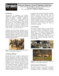
The unique, ceramic‐based formulation used in the entire line of <strong>Cerakote</strong> <strong>TM</strong> exhaust<br />
coatings enhances a number of physical characteristics. <strong>Cerakote</strong> <strong>TM</strong> exhaust coatings<br />
are durable, heat‐resistant coatings with excellent long‐term performance.<br />
Additionally, <strong>Cerakote</strong> <strong>TM</strong> ceramic exhaust coatings function as thermal barriers for<br />
thermally‐sensitive applications. This report outlines the different high‐temperature<br />
coatings available from <strong>Cerakote</strong> <strong>TM</strong> and discusses the properties inherent to each. The<br />
thermal barrier capability and chemical resistance of each coating was also studied,<br />
and the results of this study are published in this paper.<br />
Background<br />
Unlike other “ceramic” coatings, <strong>Cerakote</strong> <strong>TM</strong> is formulated from the molecular level.<br />
All <strong>Cerakote</strong> <strong>TM</strong> products begin with a liquid resin, and during the cure process, the<br />
resin forms a 3‐D ceramic matrix. Additional property‐enhancing materials are<br />
combined with the raw resin and trapped within the matrix. This technology creates a<br />
durable, heat resistant coating and makes <strong>Cerakote</strong> <strong>TM</strong> the premier exhaust coating<br />
available on the market today.<br />
<strong>Cerakote</strong> <strong>TM</strong> offers four different types of high‐temperature products. An outline of<br />
each of these coatings is shown below in table 1. As shown, <strong>Cerakote</strong> <strong>TM</strong> exhaust<br />
coatings are available in both ambient‐cure and oven cure systems. Each of the<br />
coatings may be used over a number of different substrates, including steel and<br />
aluminum. MC‐Series is also commonly used over chrome plating, PVD surfaces, and<br />
some types of powder coating for additional protection and to prevent “rain‐bowing”<br />
due to excessive heat. The average coating thickness ranges from 0.5 ‐1.0 mil and can<br />
be used in areas of low tolerance. These coatings are also VOC exempt in all 50 states<br />
and in the South Coast region of California.<br />
Table 1. Characteristics of different high‐temperature <strong>Cerakote</strong> <strong>TM</strong> exhaust coatings.<br />
Type of <strong>Cerakote</strong><strong>TM</strong> <strong>Cure</strong> Schedule General Appearance<br />
C‐Series<br />
Ambient cure;<br />
Dry to touch; 45 min<br />
Various Satin Colors<br />
MC‐Series<br />
Ambient <strong>Cure</strong>;<br />
Dry‐to‐touch; 45 min<br />
Clear<br />
W‐Series 500°F, 1 hr Chrome‐like<br />
V-Series 500°F, 1 hr Various Satin Colors<br />
16
!"#$%$%&'(#%)#*''<br />
' Thermal Barrier Testing<br />
Four different <strong>Cerakote</strong> <strong>TM</strong> products were tested to determine the potential of each as<br />
a thermal‐barrier coating. These four coatings are shown in table 2 with their<br />
respective properties. Each of these coatings were used to coat a 3’ long section of<br />
pipe. The pipes were manufactured of cold‐rolled steel and had an inner diameter of<br />
2”. The pipes were cured according to the appropriate cure schedule and then<br />
horizontally mounted using 2 clamps spaced 6” from the center of each pipe. Three<br />
thermocouples, one in the center, one 3” from the inlet and one 3” from the outlet,<br />
were positioned on each pipe. Each thermocouple was held in place using a band<br />
clamp. A gas burner was attached to the inlet side of each pipe and the pipes were<br />
heated according to the following program:<br />
Start condition: Ambient air at 100 SCFM<br />
Ramp to 572°F in 1 minute, hold for 10 minutes<br />
Ramp to 1112°F in 1 minute, hold for 10 minutes<br />
Ramp to 1706°F in 1 minute, hold for 10 minutes, and the air flow rate was<br />
maintained at 100 SCFM for the duration of the test. The inlet gas temperature and<br />
the temperatures recorded by the 3 skin thermocouples were also monitored and<br />
recorded at 1 second intervals. The results of this test are illustrated in figure 1 and<br />
further explained in table 3. At temperatures below 572°F, C‐7300 Black Velvet<br />
performed the best. Above 572°F V‐171 Turbine Coat provided the most thermal<br />
protection. At 572°F, using C‐7300 Black Velvet as a thermal barrier resulted in a<br />
110°F drop in outer skin temperature. At 1112°F and 1706°F, V‐171 Turbine Coat<br />
resulted in a 102°F and 185°F drop, respectively. Afterward, the pipes were examined<br />
in order to assess any deterioration in the physical or visual properties. C‐186, C‐7300,<br />
and V‐171 maintained adhesion of 5B as well as color and gloss. W‐207/W‐350<br />
showed a slight loss in adhesion and gloss. This can potentially be prevented by<br />
coating the inside of the pipe<br />
with V‐171 turbine coat.<br />
Table 2. Physical properties of four different <strong>Cerakote</strong><strong>TM</strong> coatings tested for thermal barrier properties.<br />
Type of <strong>Cerakote</strong><strong>TM</strong><br />
Adhesion<br />
AS<strong>TM</strong> D3359<br />
Scratch<br />
Hardness/Hardness<br />
AS<strong>TM</strong> D3363<br />
Impact<br />
AS<strong>TM</strong> 2794<br />
Mandrel Bend<br />
AS<strong>TM</strong> D522<br />
C‐186 Piston Coat 5B 5h/9h 40/20 inch‐lbs 4 mm at 180° rotation<br />
C‐7300 Black Velvet 5B 6h/7h 40/20 inch‐lbs 2 mm at 180° rotation<br />
W-207/W-350<br />
Chromex/ Base Coat<br />
5B<br />
2b/9h<br />
100/40 inch-lbs 0 mm at 180° rotation<br />
V-171 Turbine Coat 4B 4h/5h 60/20 inch-lbs 1 mm at 180° rotation<br />
17
'<br />
Figure 1<br />
!"#$%$%&'(#%)#*''<br />
Figure 1. Outer skin temperature profile for 4 pipes coated with <strong>Cerakote</strong> <strong>TM</strong> and one uncoated,<br />
cold‐rolled steel pipe over the temperature range ambient‐ 1706 0 F<br />
Table 3. <strong>Temp</strong>erature difference on outer skin of <strong>Cerakote</strong> <strong>TM</strong><br />
coated pipe as compared to bare metal pipe.<br />
<strong>Cerakote</strong> <strong>TM</strong> <strong>Temp</strong>erature Drop (°F) At<br />
572°F<br />
<strong>Temp</strong>erature Drop (°F) At<br />
1112°F<br />
<strong>Temp</strong>erature Drop (°F) At<br />
1706°F<br />
C‐186 Piston Coat 48 55 81<br />
C‐7300 Black Velvet 110 77 91<br />
W‐207/W‐350<br />
Chromex/ Base Coat<br />
77<br />
90<br />
135<br />
V‐171 Turbine Coat 88 102 185<br />
18
'<br />
Chemical Resistance<br />
!"#$%$%&'(#%)#*''<br />
The ability of <strong>Cerakote</strong> <strong>TM</strong> exhaust coatings to resist chemical breakdown was tested by<br />
dipping coated panels into a series of solvents and allowed to sit for 24 hours.<br />
Afterward, the samples were removed, analyzed and assigned a rank depending on the<br />
resistance to each specific chemical. The results of this test are shown in table 4. The<br />
performance of <strong>Cerakote</strong> <strong>TM</strong> C‐186, C‐7300, and V‐171 was classified as excellent for the<br />
solvent tests. This indicates that the coating was not affected following a 24‐hour<br />
immersion in the solvents. <strong>Cerakote</strong> <strong>TM</strong> W‐207/W‐350 performed excellent in 9 of the<br />
solvents and performed fair to good in the remaining solvents.<br />
Table 4. Chemical resistance of <strong>Cerakote</strong><strong>TM</strong> C‐186, C‐7300, W‐207/W‐350, and V‐171 to 13 different solvents<br />
Solvent<br />
<strong>Cerakote</strong><strong>TM</strong> C‐186 <strong>Cerakote</strong><strong>TM</strong> C‐7300<br />
<strong>Cerakote</strong><strong>TM</strong> W‐207/W‐350<br />
<strong>Cerakote</strong><strong>TM</strong> WD-40<br />
Motor Oil<br />
Lacquer Thinner<br />
Mineral Spirits<br />
Methyl Ethyl Ketone<br />
Gasoline<br />
Diesel<br />
Graffiti Remover<br />
Brake Cleaner<br />
Denatured Alcohol<br />
Paint Stripper<br />
Acetone<br />
Ammonia<br />
V‐171<br />
= excellent chemical resistance = good chemical resistance<br />
= fair chemical resistance = poor chemical resistance<br />
19
'<br />
For questions or comments please contact<br />
NIC Industries, Inc.<br />
7050 6th St.<br />
White City, Oregon, 97503<br />
Toll Free: (866) 774‐7628<br />
Phone: (541) 826‐ 1922<br />
Email: info@nicindustries.com<br />
Website: www.nicindustries.com<br />
Fax: (541)826‐6372<br />
Social Media<br />
Visit our YouTube Chanel Follow us on Facebook<br />
!"#$%$%&'(#%)#*''<br />
11
!<br />
!<br />
!<br />
!<br />
!<br />
!<br />
!<br />
!<br />
!<br />
!<br />
!<br />
!<br />
!<br />
!<br />
NIC Industries, Inc.<br />
7050 6th St<br />
White City, Oregon, 97503<br />
Phone:(541) 826 -1922<br />
Toll Free: (866) 774 - 7628<br />
Email: info@nicindustries.com<br />
Website:www.nicindustries.com<br />
Fax:(541) 826 - 6372