Installation and Operation Manual - Aircel Compressed Air Dryer ...
Installation and Operation Manual - Aircel Compressed Air Dryer ...
Installation and Operation Manual - Aircel Compressed Air Dryer ...

You also want an ePaper? Increase the reach of your titles
YUMPU automatically turns print PDFs into web optimized ePapers that Google loves.
<strong>Installation</strong>,<br />
<strong>Operation</strong>, <strong>and</strong><br />
Service Information<br />
Throughout this manual,<br />
signal words are present to<br />
advise of safety precautions<br />
<strong>and</strong>/or st<strong>and</strong>ard practices.<br />
Obey these signal words as defined<br />
below:<br />
DANGER! - indicates an<br />
imminently hazardous situation<br />
which, if not avoided, will result<br />
in death or serious injury.<br />
WARNING! - indicates a<br />
potentially hazardous situation<br />
which, if not avoided, could<br />
result in death or serious injury.<br />
CAUTION! - indicates a<br />
potentially hazardous situation<br />
which, if not avoided, may result<br />
in minor or moderate injury.<br />
Notice: - used to address<br />
practices not related to personal<br />
injury.<br />
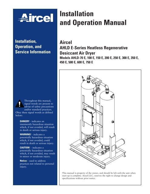
<strong>Installation</strong><br />
<strong>and</strong> <strong>Operation</strong> <strong>Manual</strong><br />
<strong><strong>Air</strong>cel</strong><br />
AHLD E-Series Heatless Regenerative<br />
Desiccant <strong>Air</strong> <strong>Dryer</strong><br />
Models AHLD-70 E, 100 E, 150 E, 200 E, 250 E, 300 E, 350 E,<br />
450 E, 500 E, 600 E, 750 E<br />
This manual is property of the owner, <strong>and</strong> should be left with the unit when<br />
start-up is complete. <strong><strong>Air</strong>cel</strong> LLC. reserves the right to change design <strong>and</strong><br />
specifications without prior notice.
<strong><strong>Air</strong>cel</strong> AHLD E-Series - Models 70 - 750<br />
2<br />
WARNING!<br />
General Safety Procedures<br />
• Improper installation, operation, or maintenance may contribute to conditions in the work<br />
area or facility that could result in personal injury <strong>and</strong> product or property damage. Check<br />
that all equipment is properly selected <strong>and</strong> sized for the intended use.<br />
• Consult <strong>and</strong> comply with national <strong>and</strong> local codes relating to fire or explosion <strong>and</strong> all<br />
other appropriate codes when determining the location <strong>and</strong> operation of this equipment.<br />
• Safe <strong>and</strong> efficient operation of the unit depends on proper installation.<br />
• Authorities with jurisdiction should be consulted before installing to verify local codes <strong>and</strong><br />
installation procedures. In the absence of such codes, install unit according to the National<br />
Electric Code, NFPA No. 70-latest edition.<br />
• A qualified installation <strong>and</strong> service agent must complete installation <strong>and</strong> service of this<br />
equipment.<br />
• DO NOT weld on / to pressure vessel or modify it in any way.<br />
• DO NOT remove, modify, or adjust protective or safety devices.<br />
• Lock out power supply <strong>and</strong> depressurize system before performing maintenance or service<br />
work.<br />
• DO NOT operate the equipment with the control panel door open.<br />
Notice: For optimum performance, use only <strong><strong>Air</strong>cel</strong> replacement parts.<br />
Notice: For optimum performance, use only original equipment replacement parts.<br />
Notice: For information <strong>and</strong> notes specific to a custom designed <strong>and</strong> built dryer, reference the<br />
drawing package provided with the unit. See warranty on manual back cover for<br />
custom engineered products.<br />
This manual contains specific precautionary statements relative to worker safety.<br />
Read thoroughly <strong>and</strong> comply as directed. Discuss the use <strong>and</strong> application of this<br />
equipment with a representative. Instruct all personnel on safe use <strong>and</strong> maintenance<br />
procedures. Underst<strong>and</strong> <strong>and</strong> obey the following signal words used in this manual.<br />
• DANGER! - indicates an imminently hazardous situation which, if not avoided, will<br />
result in death or serious injury.<br />
• WARNING! - indicates a potentially hazardous situation which, if not avoided, could<br />
result in death or serious injury.<br />
• CAUTION! - indicates a potentially hazardous situation which, if not avoided, may<br />
result in minor or moderate injury.<br />
• Notice: - used to address practices not related to personal injury.
Contents<br />
Safety Statements .................................................. 2<br />
Introduction .......................................................... 3<br />
Data Sheet ............................................................. 4<br />
Safety Symbols ...................................................... 5<br />
General Safety Instructions ................................... 6<br />
Description............................................................ 7<br />
Purpose & Intended Use .............................. 7<br />
Features & Options ..................................... 8<br />
Inspection on Arrival ............................................ 9<br />
Technical Specifications ...................................... 10<br />
How it Works Diagram ...................................... 11<br />
<strong>Installation</strong> .......................................................... 12<br />
Typical <strong>Installation</strong> ............................................. 12<br />
<strong>Installation</strong> Checklist .......................................... 13<br />
Start-Up Procedure .............................................. 14<br />
Shut-Down Procedure ......................................... 15<br />
Introduction<br />
Heatless Regenerative Desiccant <strong>Air</strong> <strong>Dryer</strong><br />
Thank you for purchasing <strong><strong>Air</strong>cel</strong>’s AHLD-E Series Heatless Regenerative Desiccant <strong>Air</strong> <strong>Dryer</strong> with<br />
Integrated Energy Management Purge Reduction System. You are now the proud owner of one of the finest<br />
desiccant dryers in the market. <strong><strong>Air</strong>cel</strong> AHLD-E series dryers are engineered <strong>and</strong> manufactured to provide<br />
you with many years of trouble free service <strong>and</strong> provides energy efficient operation by reducing the overall<br />
dry purge air required for regeneration saving energy <strong>and</strong> money. To ensure that you get the get first class<br />
service from this equipment, we recommend you take some time <strong>and</strong> read the contents of this manual.<br />
This manual contains all the information required for installing <strong>and</strong> maintaining your new equipment. It<br />
also includes the safety procedures <strong>and</strong> corresponding drawings. We strongly suggest that all personnel<br />
involved with the machine, read the entire contents of the manual before proceeding with the installation or<br />
maintenance activities.<br />
The manufacturer reserves the right to make changes without any prior notification <strong>and</strong> is not obligated in<br />
any manner. Information in this manual is deemed current at the time of publication <strong>and</strong> <strong><strong>Air</strong>cel</strong> disclaims all<br />
liability for any errors resulting in any loss or damage.<br />
If you have questions or need additional copies or would like to schedule a <strong><strong>Air</strong>cel</strong>'s serviceman visit, contact<br />
your distributor.<br />
<strong><strong>Air</strong>cel</strong><br />
323 Crisp Circle<br />
Maryville, TN 37801<br />
Toll-Free: (800) 767-4599<br />
Tel: (865) 681-7066<br />
Fax: (865) 681-7069<br />
Sequence of <strong>Operation</strong> ........................................ 15<br />
Service Information ............................................. 17<br />
Maintenance & Checklists ......................... 17<br />
Troubleshooting .................................................. 19<br />
Troubleshooting Table ........................................ 20<br />
Desiccant Material Safety Data Sheet .................. 22<br />
<strong><strong>Air</strong>cel</strong> Programmable Controller ......................... 27<br />
Electrical Drawings ............................................. 36<br />
Main Power & PLC Input.......................... 36<br />
PLC Output & Sensors .............................. 38<br />
Back Panel .................................................. 40<br />
Enclosure Layout ....................................... 41<br />
Service Notes ...................................................... 42<br />
Warranty............................................................. 44<br />
Sales Information:<br />
sales@<strong><strong>Air</strong>cel</strong><strong>Dryer</strong>s.com<br />
Order Entry:<br />
orderentry@<strong><strong>Air</strong>cel</strong><strong>Dryer</strong>s.com<br />
www.<strong><strong>Air</strong>cel</strong><strong>Dryer</strong>s.com<br />
3
<strong><strong>Air</strong>cel</strong> AHLD E-Series - Models 70 - 750<br />
Data Sheet<br />
4<br />
Model Number _ _ _ _ _ _ _ _ _ _ _ _ _ _ _ _ _ _ _ _ _ _ _ _ _ _ _ _ _ _ _ _ _ _ _ _ _ Serial Number _ _ _ _ _ _ _ _ _ _ _ _ _ _ _ _ _ _ _ _ _ _ _ _ _ _ _ _ _ _ _ _ _ _ _ _ _ _ _ _<br />
<strong>Dryer</strong> Type _ _ _ _ _ _ _ _ _ _ _ _ _ _ _ _ _ _ _ _ _ _ _ _ _ _ _ _ _ _ _ _ _ _ _ _ _ _ _ _ Date of Manufacture _ _ _ _ _ _ _ _ _ _ _ _ _ _ _ _ _ _ _ _ _ _ _ _ _ _ _ _ _ _ _ _ _ _<br />
Ship Date _ _ _ _ _ _ _ _ _ _ _ _ _ _ _ _ _ _ _ _ _ _ _ _ _ _ _ _ _ _ _ _ _ _ _ _ _ _ _ _ _ _ <strong>Installation</strong> Date _ _ _ _ _ _ _ _ _ _ _ _ _ _ _ _ _ _ _ _ _ _ _ _ _ _ _ _ _ _ _ _ _ _ _ _ _ _<br />
Customer Name _ _ _ _ _ _ _ _ _ _ _ _ _ _ _ _ _ _ _ _ _ _ _ _ _ _ _ _ _ _ _ _ _ _ _ _ Address _ _ _ _ _ _ _ _ _ _ _ _ _ _ _ _ _ _ _ _ _ _ _ _ _ _ _ _ _ _ _ _ _ _ _ _ _ _ _ _ _ _ _ _ _ _<br />
Address Cont’d _ _ _ _ _ _ _ _ _ _ _ _ _ _ _ _ _ _ _ _ _ _ _ _ _ _ _ _ _ _ _ _ _ _ _ _ _ _ _ _ _ _ _ _ _ _ _ _ _ _ _ _ _ _ _ _ _ _ _ _ _ _ _ _ _ _ _ _ _ _ _ _ _ _ _ _ _ _ _ _ _ _ _ _ _ _ _ _ _ _<br />
Accessories _ _ _ _ _ _ _ _ _ _ _ _ _ _ _ _ _ _ _ _ _ _ _ _ _ _ _ _ _ _ _ _ _ _ _ _ _ _ _ _ _ _ _ _ _ _ _ _ _ _ _ _ _ _ _ _ _ _ _ _ _ _ _ _ _ _ _ _ _ _ _ _ _ _ _ _ _ _ _ _ _ _ _ _ _ _ _ _ _ _ _ _ _ _ _ _ _ _ _ _ _ _ _ _ _ _ _ _ _ _ _ _ _ _ _<br />
Other _ _ _ _ _ _ _ _ _ _ _ _ _ _ _ _ _ _ _ _ _ _ _ _ _ _ _ _ _ _ _ _ _ _ _ _ _ _ _ _ _ _ _ _ _ _ _ _ _ _ _ _ _ _ _ _ _ _ _ _ _ _ _ _ _ _ _ _ _ _ _ _ _ _ _ _ _ _ _ _ _ _ _ _ _ _ _ _ _ _ _ _ _ _ _ _ _ _ _ _ _ _ _ _ _ _ _ _ _ _ _ _ _ _ _ _ _ _ _ _ _ _<br />
<strong>Dryer</strong> Inlet <strong>Air</strong> Flow Rate _ _ _ _ _ _ _ _ _ _ _ _ _ _ _ _ _ _ _ _ _ _ _ _ _ _ _ _ _ _ _ _ _ _ _ _ _ _ _ _ _ _ _ _ _ _ _ _ _ _ _ _ _ _ _ _ _ _ _ _ _ _ _ _ _ _ _ _ _ _ _ _ _ _ _ _ _ _ _ _ _ _ _ _ _ _ _ _<br />
<strong>Dryer</strong> Inlet Temperature _ _ _ _ _ _ _ _ _ _ _ _ _ _ _ _ _ _ _ _ _ _ _ _ _ _ _ _ _ _ _ _ _ _ _ _ _ _ _ _ _ _ _ _ _ _ _ _ _ _ _ _ _ _ _ _ _ _ _ _ _ _ _ _ _ _ _ _ _ _ _ _ _ _ _ _ _ _ _ _ _ _ _ _ _ _ _ _ _ _<br />
<strong>Dryer</strong> Ambient Temperature _ _ _ _ _ _ _ _ _ _ _ _ _ _ _ _ _ _ _ _ _ _ _ _ _ _ _ _ _ _ _ _ _ _ _ _ _ _ _ _ _ _ _ _ _ _ _ _ _ _ _ _ _ _ _ _ _ _ _ _ _ _ _ _ _ _ _ _ _ _ _ _ _ _ _ _ _ _ _ _ _ _ _ _<br />
<strong>Dryer</strong> Voltage _ _ _ _ _ _ _ _ _ _ _ _ _ _ _ _ _ _ _ _ _ _ _ _ _ _ _ _ _ _ _ _ _ _ _ _ _ _ _ _ _ _ _ _ _ _ _ _ _ _ _ _ _ _ _ _ _ _ _ _ _ _ _ _ _ _ _ _ _ _ _ _ _ _ _ _ _ _ _ _ _ _ _ _ _ _ _ _ _ _ _ _ _ _ _ _ _ _ _ _ _ _<br />
<strong>Dryer</strong> MCA Minimum Circuit Ampacity _ _ _ _ _ _ _ _ _ _ _ _ _ _ _ _ _ _ _ _ _ _ _ _ _ _ _ _ _ _ _ _ _ _ _ _ _ _ _ _ _ _ _ _ _ _ _ _ _ _ _ _ _ _ _ _ _ _ _ _ _ _ _ _ _ _ _ _ _<br />
<strong>Dryer</strong> MOP Maximum Overcurrent Protection _ _ _ _ _ _ _ _ _ _ _ _ _ _ _ _ _ _ _ _ _ _ _ _ _ _ _ _ _ _ _ _ _ _ _ _ _ _ _ _ _ _ _ _ _ _ _ _ _ _ _ _ _ _ _ _ _ _ _ _ _ _<br />
<strong>Dryer</strong> Operating Pressure _ _ _ _ _ _ _ _ _ _ _ _ _ _ _ _ _ _ _ _ _ _ _ _ _ _ _ _ _ _ _ _ _ _ _ _ _ _ _ _ _ _ _ _ _ _ _ _ _ _ _ _ _ _ _ _ _ _ _ _ _ _ _ _ _ _ _ _ _ _ _ _ _ _ _ _ _ _ _ _ _ _ _ _ _ _ _ _<br />
<strong>Dryer</strong> Maximum Operating Pressure _ _ _ _ _ _ _ _ _ _ _ _ _ _ _ _ _ _ _ _ _ _ _ _ _ _ _ _ _ _ _ _ _ _ _ _ _ _ _ _ _ _ _ _ _ _ _ _ _ _ _ _ _ _ _ _ _ _ _ _ _ _ _ _ _ _ _ _ _ _ _ _ _ _<br />
<strong>Dryer</strong> Vessel Pressure Relief Valve Setting _ _ _ _ _ _ _ _ _ _ _ _ _ _ _ _ _ _ _ _ _ _ _ _ _ _ _ _ _ _ _ _ _ _ _ _ _ _ _ _ _ _ _ _ _ _ _ _ _ _ _ _ _ _ _ _ _ _ _ _ _ _ _ _ _ _ _ _<br />
<strong>Dryer</strong> Desiccant Type _ _ _ _ _ _ _ _ _ _ _ _ _ _ _ _ _ _ _ _ _ _ _ _ _ _ _ _ _ _ _ _ _ _ _ _ _ _ _ _ _ _ _ _ _ _ _ _ _ _ _ _ _ _ _ _ _ _ _ _ _ _ _ _ _ _ _ _ _ _ _ _ _ _ _ _ _ _ _ _ _ _ _ _ _ _ _ _ _ _ _ _ _<br />
<strong>Dryer</strong> Desiccant Weight per Vessel _ _ _ _ _ _ _ _ _ _ _ _ _ _ _ _ _ _ _ _ _ _ _ _ _ _ _ _ _ _ _ _ _ _ _ _ _ _ _ _ _ _ _ _ _ _ _ _ _ _ _ _ _ _ _ _ _ _ _ _ _ _ _ _ _ _ _ _ _ _ _ _ _ _ _ _ _<br />
<strong>Dryer</strong> Desiccant Weight Total for System _ _ _ _ _ _ _ _ _ _ _ _ _ _ _ _ _ _ _ _ _ _ _ _ _ _ _ _ _ _ _ _ _ _ _ _ _ _ _ _ _ _ _ _ _ _ _ _ _ _ _ _ _ _ _ _ _ _ _ _ _ _ _ _ _ _ _ _ _<br />
<strong>Dryer</strong> Outlet Dewpoint _ _ _ _ _ _ _ _ _ _ _ _ _ _ _ _ _ _ _ _ _ _ _ _ _ _ _ _ _ _ _ _ _ _ _ _ _ _ _ _ _ _ _ _ _ _ _ _ _ _ _ _ _ _ _ _ _ _ _ _ _ _ _ _ _ _ _ _ _ _ _ _ _ _ _ _ _ _ _ _ _ _ _ _ _ _ _ _ _ _ _<br />
<strong>Dryer</strong> Control Time Cycle _ _ _ _ _ _ _ _ _ _ _ _ _ _ _ _ _ _ _ _ _ _ _ _ _ _ _ _ _ _ _ _ _ _ _ _ _ _ _ _ _ _ _ _ _ _ _ _ _ _ _ _ _ _ _ _ _ _ _ _ _ _ _ _ _ _ _ _ _ _ _ _ _ _ _ _ _ _ _ _ _ _ _ _ _ _ _<br />
<strong>Dryer</strong> EMS RH Sensor Setting (for sensing mid-bed moisture) _ _ _ _ _ _ _ _ _ _ _ _ _ _ _ _ _ _ _ _ _ _ _ _ _ _ _ _ _ _ _ _ _ _ _ _ _ _ _ _ _ _ _<br />
High Dewpoint Setting (option) _ _ _ _ _ _ _ _ _ _ _ _ _ _ _ _ _ _ _ _ _ _ _ _ _ _ _ _ _ _ _ _ _ _ _ _ _ _ _ _ _ _ _ _ _ _ _ _ _ _ _ _ _ _ _ _ _ _ _ _ _ _ _ _ _ _ _ _ _ _ _ _ _ _ _ _ _ _ _ _<br />
Dem<strong>and</strong> Cycle Setting (option) _ _ _ _ _ _ _ _ _ _ _ _ _ _ _ _ _ _ _ _ _ _ _ _ _ _ _ _ _ _ _ _ _ _ _ _ _ _ _ _ _ _ _ _ _ _ _ _ _ _ _ _ _ _ _ _ _ _ _ _ _ _ _ _ _ _ _ _ _ _ _ _ _ _ _ _ _ _ _ _ _<br />
Outlet Dewpoint Readout on Display (option) _ _ _ _ _ _ _ _ _ _ _ _ _ _ _ _ _ _ _ _ _ _ _ _ _ _ _ _ _ _ _ _ _ _ _ _ _ _ _ _ _ _ _ _ _ _ _ _ _ _ _ _ _ _ _ _ _ _ _ _ _ _<br />
Electrical Drawing No. _ _ _ _ _ _ _ _ _ _ _ _ _ _ _ _ _ _ _ _ _ _ _ _ _ _ _ _ _ _ _ _ _ _ _ _ _ _ _ _ _ _ _ _ _ _ _ _ _ _ _ _ _ _ _ _ _ _ _ _ _ _ _ _ _ _ _ _ _ _ _ _ _ _ _ _ _ _ _ _ _ _ _ _ _ _ _ _ _ _ _<br />
Mechanical Drawing No. _ _ _ _ _ _ _ _ _ _ _ _ _ _ _ _ _ _ _ _ _ _ _ _ _ _ _ _ _ _ _ _ _ _ _ _ _ _ _ _ _ _ _ _ _ _ _ _ _ _ _ _ _ _ _ _ _ _ _ _ _ _ _ _ _ _ _ _ _ _ _ _ _ _ _ _ _ _ _ _ _ _ _ _ _ _ _ _<br />
PLC Software Program No. _ _ _ _ _ _ _ _ _ _ _ _ _ _ _ _ _ _ _ _ _ _ _ _ _ _ _ _ _ _ _ _ _ _ _ _ _ _ _ _ _ _ _ _ _ _ _ _ _ _ _ _ _ _ _ _ _ _ _ _ _ _ _ _ _ _ _ _ _ _ _ _ _ _ _ _ _ _ _ _ _ _ _ _ _<br />
Control <strong>Air</strong> Filter Element No. _ _ _ _ _ _ _ _ _ _ _ _ _ _ _ _ _ _ _ _ _ _ _ _ _ _ _ _ _ _ _ _ _ _ _ _ _ _ _ _ _ _ _ _ _ _ _ _ _ _ _ _ _ _ _ _ _ _ _ _ _ _ _ _ _ _ _ _ _ _ _ _ _ _ _ _ _ _ _ _ _<br />
Inlet Pre-Filter Element No. (option) _ _ _ _ _ _ _ _ _ _ _ _ _ _ _ _ _ _ _ _ _ _ _ _ _ _ _ _ _ _ _ _ _ _ _ _ _ _ _ _ _ _ _ _ _ _ _ _ _ _ _ _ _ _ _ _ _ _ _ _ _ _ _ _ _ _ _ _ _ _ _ _ _ _ _<br />
Outlet After-Filter Element No. (option) _ _ _ _ _ _ _ _ _ _ _ _ _ _ _ _ _ _ _ _ _ _ _ _ _ _ _ _ _ _ _ _ _ _ _ _ _ _ _ _ _ _ _ _ _ _ _ _ _ _ _ _ _ _ _ _ _ _ _ _ _ _ _ _ _ _ _ _ _ _ _<br />
Inlet Valve _ _ _ _ _ _ _ _ _ _ _ _ _ _ _ _ _ _ _ _ _ _ _ _ _ _ _ _ _ _ _ _ _ _ _ _ _ _ _ _ _ _ _ _ _ _ _ _ _ _ _ _ _ _ _ _ _ _ _ _ _ _ _ _ _ _ _ _ _ _ _ _ _ _ _ _ _ _ _ _ _ _ _ _ _ _ _ _ _ _ _ _ _ _ _ _ _ _ _ _ _ _ _ _ _ _<br />
Purge Exhaust Valve _ _ _ _ _ _ _ _ _ _ _ _ _ _ _ _ _ _ _ _ _ _ _ _ _ _ _ _ _ _ _ _ _ _ _ _ _ _ _ _ _ _ _ _ _ _ _ _ _ _ _ _ _ _ _ _ _ _ _ _ _ _ _ _ _ _ _ _ _ _ _ _ _ _ _ _ _ _ _ _ _ _ _ _ _ _ _ _ _ _ _ _ _ _<br />
Vessel National Board No. (left <strong>and</strong> right vessels) _ _ _ _ _ _ _ _ _ _ _ _ _ _ _ _ _ _ _ _ _ _ _ _ _ _ _ _ _ _ _ _ _ _ _ _ _ _ _ _ _ _ _ _ _ _ _ _ _ _ _ _ _ _ _ _ _ _<br />
<strong>Dryer</strong> System Weight _ _ _ _ _ _ _ _ _ _ _ _ _ _ _ _ _ _ _ _ _ _ _ _ _ _ _ _ _ _ _ _ _ _ _ _ _ _ _ _ _ _ _ _ _ _ _ _ _ _ _ _ _ _ _ _ _ _ _ _ _ _ _ _ _ _ _ _ _ _ _ _ _ _ _ _ _ _ _ _ _ _ _ _ _ _ _ _ _ _ _ _ _
Safety Instructions<br />
Safety Symbols Used in <strong>Manual</strong><br />
Heatless Regenerative Desiccant <strong>Air</strong> <strong>Dryer</strong><br />
Important Information: Readers of the manual must pay extra attention to<br />
instructions <strong>and</strong> information succeeding this symbol.<br />
Warning: This indicates that it is dangerous <strong>and</strong> could result in physical injury <strong>and</strong><br />
death if the instructions are not followed correctly.<br />
Electrical Danger High Voltage: This means that there is a risk of electric shock <strong>and</strong><br />
only authorized personnel with proper gear must approach it.<br />
High Noise Area: All personnel are required to wear ear protectors before<br />
approaching the vicinity of the equipment.<br />
Hazardous Fumes & Gases: Personnel must wear protective gear to prevent inhaling<br />
of the gases <strong>and</strong> fumes.<br />
Suspension Points: Look for these symbols before making any attempt to move or<br />
relocate your equipment.<br />
Tips & Suggestions: Following these tips can make your work easier.<br />
Extreme Caution: This indicates that there might be possible risk of material damage<br />
<strong>and</strong> personnel are advised to exercise extra caution.<br />
5
<strong><strong>Air</strong>cel</strong> AHLD E-Series - Models 70 - 750<br />
General Safety Instructions<br />
What You Must Do<br />
1. Certified/authorized electricians must perform electrical work<br />
2. Electrical work must conform to the specifications indicated by <strong><strong>Air</strong>cel</strong> <strong>and</strong> any local or state laws that<br />
may apply.<br />
3. Personnel must wear appropriate safety gear before working on any electrical or mechanical aspects of<br />
the machine.<br />
4. Appropriate tools have to be used for all installation <strong>and</strong> maintenance work. If special tools are required<br />
<strong>and</strong> are not available to the installation crew, contact the factory or your <strong><strong>Air</strong>cel</strong> representative.<br />
5. A copy of the <strong>Operation</strong> <strong>Manual</strong> must be made available to all personnel involved with the installation,<br />
operation <strong>and</strong> maintenance of the equipment.<br />
6. Before performing any maintenance operations on the equipment, the unit must be shut down, isolated,<br />
electrical power removed, <strong>and</strong> completely depressurized.<br />
7. To ensure compatibility <strong>and</strong> continued trouble free operation, only genuine <strong><strong>Air</strong>cel</strong> parts must be used.<br />
What You Must Not Do<br />
1. Do not make constructional changes to the unit. Only <strong><strong>Air</strong>cel</strong> or its authorized representatives with the<br />
prior approval can perform any constructional work on the machine.<br />
2. Do not use foreign parts.<br />
3. <strong>Compressed</strong> air from the dryers is not to be used for breathing purposes – install a breathing air package<br />
to ensure conformance with OSHA regulations<br />
4. Do not disable or disengage any protective equipment used on the machine.<br />
Safe Operating Procedures<br />
1. Pressurize <strong>and</strong> depressurize compressed air SLOWLY! Always open air valves slowly when pressurizing<br />
the airline system or equipment. Replace air slowly when depressurizing your air system or equipment.<br />
2. Circuit breakers, fusible disconnect, <strong>and</strong> wiring should conform to national <strong>and</strong>/or local electrical codes.<br />
Make certain that qualified electrical personnel perform the electrical installation for this unit.<br />
3. Only use original fuses for the rated voltage <strong>and</strong> current.<br />
4. Shut down the unit in the correct recommended procedure.<br />
5. Before any work on system always Depressurize the unit <strong>and</strong> remove all electrical power.<br />
6. After shut down, put up warning notice to prevent the unit from being switched “ON” accidentally.<br />
7. Inspect all piping, hoses <strong>and</strong> connections. Make sure that all hoses are in good condition <strong>and</strong> are rated<br />
for the correct working pressure. Do not allow hoses to come into contact with oil, chemicals, or sharp<br />
objects.<br />
8. Secure condensate drain lines. Unsecured flexible drain lines may whip violently under pressure <strong>and</strong> may<br />
cause bodily harm.<br />
6<br />
<strong><strong>Air</strong>cel</strong> air dryers do not remove carbon monoxide <strong>and</strong> is not safe for human respiration (breathing).<br />
Breathing air must be at least grade D quality as described in compressed air <strong>and</strong> gas association (CAGI)<br />
commodity specifications 67.1-1966. User may refer to OSHA 29 CFI 1910.134 for special precautions<br />
<strong>and</strong> equipment suitable for breathing air applications. <strong><strong>Air</strong>cel</strong> disclaims any liability what so ever for loss,<br />
injury or damage.
Product Description<br />
Why We Need <strong>Compressed</strong> <strong>Air</strong> <strong>Dryer</strong>s<br />
Heatless Regenerative Desiccant <strong>Air</strong> <strong>Dryer</strong><br />
Untreated compressed air contains many contaminants such as water, compressor oil, pipe scale <strong>and</strong><br />
contamination from ambient air. All these contaminants cause excessive corrosion, erosion, freezing <strong>and</strong><br />
product contamination to all components that come in contact with the untreated compressed air. A<br />
regenerative type dryer system with all recommended filtration will remove these contaminants to harmless<br />
levels. The end result is that instruments that come in contact with the dry compressed air stay clean <strong>and</strong> do<br />
not corrode, therefore lasting much longer. Products that may come in contact with clean dry compressed<br />
air are virtually unaffected. Therefore rejection rates are reduced.<br />
Purpose & Intended Use<br />
<strong><strong>Air</strong>cel</strong> Regenerative Desiccant <strong>Air</strong> <strong>Dryer</strong>s can dry compressed air to -100°F PDP (Pressure Dew Point),<br />
St<strong>and</strong>ard Regenerative Desiccant <strong>Air</strong> <strong>Dryer</strong>s dry compressed air down to -40°F PDP. The compressed air<br />
stream is passed through a desiccant bed, which removes the moisture through the process of adsorption.<br />
Twin towers filled with desiccant alternate between drying <strong>and</strong> regeneration either based on the Energy<br />
Management System (EMS) control or a fixed time cycle. <strong><strong>Air</strong>cel</strong> manufactures various types of desiccant air/<br />
gas dryers. These dryers offer fail-safe design in the event of power interruption. <strong>Air</strong> will continue to flow<br />
through the dryer without deadheading; also purge exhaust valves will close preventing loss of air pressure.<br />
The tower operating status lights <strong>and</strong> the highest quality non-lubricated air/gas inlet valves will ensure<br />
reliable operation for many years to come.<br />
7
<strong><strong>Air</strong>cel</strong> AHLD E-Series - Models 70 - 750<br />
St<strong>and</strong>ard Features<br />
• Integrated Energy Management Purge Reduction System for efficient energy savings <strong>and</strong> reduced cost of<br />
operation.<br />
• Optimal tower size for low velocities reducing desiccant fluidization, <strong>and</strong> high contact time for efficient<br />
low dewpoint performance.<br />
• Tower pressure relief valves.<br />
• St<strong>and</strong>ard design capacity based on 100 psig, 100°F inlet air, 100°F ambient air <strong>and</strong> PDP of -40°F.<br />
• Purge exhaust mufflers for quiet operation.<br />
• Tower pressure gauges for additional visual operation of dryer operation.<br />
• Stainless steel desiccant supports <strong>and</strong> air diffusers to prevent channeling.<br />
• Counter-current reactivation for efficient desiccant regeneration.<br />
• PLC Controlled Electrical System<br />
• Adjustable (5 min., 10 min.) Cycle times: 10 minute cycle for the st<strong>and</strong>ard -40°F PDP outlet dewpoint<br />
systems, 5 minute cycle used in the optional -100°F PDP outlet dewpoint systems.<br />
• Controlled repressurization to slowly repressurize the regenerated vessel to line pressure prior to switch<br />
over preventing desiccant bed movement <strong>and</strong> attrition.<br />
• Fail safe design: failure of power <strong>and</strong>/or pilot air causes the purge exhaust valves to close eliminating<br />
loss of air pressure. The System also provides uninterrupted drying air flow preventing a deadheading<br />
affect.<br />
• Control pilot air filter provides clean air to air control system for long trouble-free reliable operation.<br />
• Desiccant towers are designed, fabricated <strong>and</strong> stamped according to ASME code. (AHLD-70 E <strong>and</strong> up).<br />
• Desiccant fill <strong>and</strong> drain ports for ease of desiccant replacement.<br />
• Structural steel frame<br />
• Highly reliable non-lubricated air inlet <strong>and</strong> outlet valves (APV) Automatic Piston Valve (AHLD-70 E —<br />
AHLD-750 E)<br />
• Highly reliable angle seat design purge exhaust valves (AHLD-70 E — AHLD-750 E).<br />
• Tower operating L.E.D. status lights (Left Tower Drying, Right Tower Drying, Left Tower<br />
Regenerating, Right Tower Regenerating)<br />
• ON/OFF switch <strong>and</strong> power ON light.<br />
• NEMA 4 weather resistant electrical system construction.<br />
Additional Options<br />
• -100°F outlet pressure dew point<br />
• Failure-to-shift alarm (with pressure transducers)<br />
• Outlet dewpoint sensor with dewpoint readout on system display<br />
• High humidity alarm<br />
• Outlet dewpoint 4-20 ma signal<br />
• Mounted, piped <strong>and</strong> wired filtration packages<br />
8
Inspection on Arrival<br />
All <strong><strong>Air</strong>cel</strong> dryers are tested <strong>and</strong> operated before<br />
shipment. However, shipping stresses have the<br />
potential to cause damage to the unit. To ensure<br />
smooth installation, it is recommended that<br />
immediately upon receipt of the unit, the system is<br />
checked for the following:<br />
1. Make sure you have received all the crates/<br />
packages that are indicated in the packing slip.<br />
2. Remove the crate <strong>and</strong> packaging. Inspect the<br />
unit for any visible damage.<br />
3. Report any damage to the delivery carrier.<br />
4. Request a written inspection report from the<br />
Claims Inspector to substantiate the claim.<br />
5. File claims with the delivery carrier.<br />
6. Compare unit received with description of<br />
product ordered. Check the serial plate label<br />
<strong>and</strong> make sure that it is the correct Model was<br />
ordered. Note the equipment Capacity <strong>and</strong><br />
Power Supply requirements <strong>and</strong> ensure that they<br />
are in accordance with your specifications. The<br />
rated conditions of the dryer are indicated on<br />
the serial plate label. If there is any discrepancy,<br />
contact your representative listed on the manual<br />
back cover.<br />
7. Shipping stresses can loosen connections.<br />
All pipe <strong>and</strong> tubing connections should be<br />
inspected.<br />
8. Report incomplete shipments to the<br />
delivery carrier <strong>and</strong> your <strong><strong>Air</strong>cel</strong> service<br />
representative.<br />
Heatless Regenerative Desiccant <strong>Air</strong> <strong>Dryer</strong><br />
CAUTION!<br />
• Do not misuse or modify under any<br />
conditions. Misuse or modification<br />
of this equipment may result in<br />
personal injury.<br />
9
<strong><strong>Air</strong>cel</strong> AHLD E-Series - Models 70 - 750<br />
Technical Specifications<br />
How Does it Work? (see diagram 1)<br />
Moisture saturated compressed air enters the<br />
coalescing pre filter (F1) where aerosols are<br />
coalesced then drained via an automatic drain<br />
system. The moist water vapor-laden inlet air<br />
free of liquid water flows to the inlet of the dryer<br />
through the APV (Automatic Piston Valve) (V1)<br />
which diverts the inlet air to one of the towers, in<br />
this example tower (T1). <strong>Air</strong> flows upward through<br />
the adsorbent bed removing the moisture vapor,<br />
the dried airflow exits the tower through the outlet<br />
APV valve (V2) flowing to the outlet particulate<br />
after filter (F2) which removes particulates from<br />
the air stream. Clean <strong>and</strong> dry air now flows to the<br />
process air distribution system.<br />
As one tower is drying air, the other tower will be<br />
regenerating (purging) the adsorbent bed. In this<br />
example, tower (T2) will be regenerating. Prior<br />
to regeneration, the exhaust valve (V4) is opened<br />
<strong>and</strong> the tower is depressurized to near atmospheric<br />
pressure, the tower will now be regenerating.<br />
During the regenerating process a small portion of<br />
dry outlet compressed air is used, 15% on average<br />
based on st<strong>and</strong>ard design capacity of 100 psig,<br />
100°F inlet air, 100°F ambient air <strong>and</strong> PDP of<br />
-40°F. The dry regeneration airflow is channeled<br />
through the outlet APV valve to the regenerating<br />
tower (T2) removing moisture from the adsorbent<br />
bed <strong>and</strong> exits the regenerating tower (T2) through<br />
exhaust valve (V4) <strong>and</strong> exhaust muffler to ambient.<br />
After regeneration cycle is complete, valve (V4)<br />
closes causing tower (T2) to repressurize to line<br />
pressure.<br />
10<br />
Next, the towers will switch when exhaust valve<br />
(V3) opens causing tower (T1) to depressurize <strong>and</strong><br />
regenerate, simultaneously the inlet <strong>and</strong> outlet APV<br />
valves (V1) <strong>and</strong> (V2) will shift the pistons to the<br />
low pressure tower (T1) causing the inlet airflow<br />
to be diverted to tower (T2) which will now be the<br />
drying tower. This switching process will continue<br />
repeatedly.<br />
The dryer control system is completely automatic<br />
<strong>and</strong> cycles the system through the drying <strong>and</strong><br />
regeneration cycles. The st<strong>and</strong>ard cycle drying time<br />
is 5 minutes, regeneration cycle is 4 minutes, <strong>and</strong><br />
repressurizing cycle is 1 minute.<br />
The <strong><strong>Air</strong>cel</strong> AHLD E-Series Heatless <strong>Dryer</strong><br />
incorporates a unique energy saving control system<br />
to reduce purge air loss with its integrated Energy<br />
Management Purge Reduction System which utilizes<br />
a moisture sensor sampling the air from mid bed of<br />
the on-stream drying tower, after the fixed purge<br />
time is complete the regenerating/purging tower will<br />
repressurize. If the moisture sensor senses a low<br />
moisture condition or low load in the drying tower,<br />
the drying tower will remain in the drying mode<br />
after the fixed drying time cycle for an extended<br />
period of time. The end result is an overall purge<br />
reduction <strong>and</strong> significant energy savings.<br />
CAUTION!<br />
• Do not misuse or modify under any<br />
conditions. Misuse or modification<br />
of this equipment may result in<br />
personal injury.
<strong>Air</strong> Saturated with Moisture<br />
Regeneration <strong>Air</strong><br />
Dry <strong>Air</strong><br />
F1<br />
T1<br />
Drying<br />
Tower<br />
V3<br />
V2<br />
V1<br />
V4<br />
T2<br />
Regenerating<br />
Tower<br />
Diagram 1: How it Works<br />
Heatless Regenerative Desiccant <strong>Air</strong> <strong>Dryer</strong><br />
F2<br />
F1 - Mounted Pre-Filter<br />
F2 - Mounted After-Filter<br />
V1 - Automatic Piston Valve<br />
V2 - Automatic Piston Valve<br />
V3 - Purge Exhaust Valve<br />
V4 - Purge Exhaust Valve<br />
T1 - Desiccant Tower 1<br />
T2 - Desiccant Tower 2<br />
11
<strong><strong>Air</strong>cel</strong> AHLD E-Series - Models 70 - 750<br />
<strong>Installation</strong><br />
Pre-requisites for <strong>Installation</strong><br />
To ensure a safe <strong>and</strong> smooth installation, we recommend you go through the steps indicated below:<br />
12<br />
• Make sure that all personnel involved have read this <strong>Operation</strong> <strong>Manual</strong> thoroughly. If you have<br />
any questions, feel free to contact your <strong><strong>Air</strong>cel</strong> representative or the factory <strong>and</strong> we will be glad<br />
to assist you. If you need help with the commissioning, we will be glad to schedule a factory<br />
serviceman to visit your site <strong>and</strong> commission the dryer for a nominal fee.<br />
• Have extra copies of the <strong>Operation</strong> <strong>Manual</strong>s.<br />
• Special care must be taken while transporting the unit to the installation site.<br />
• <strong>Dryer</strong> must not be moved or lifted by the attached piping.<br />
Location<br />
• Careful consideration should be given to the location of the dryer in order to assure optimum<br />
results. Ensure that the load bearing weight of the floor is adequate for the weight of the dryer.<br />
• The dryer should be located in an open area <strong>and</strong> a level ground. <strong>Dryer</strong> should be bolted to the floor<br />
to eliminate vibrations.<br />
• The ambient temperature should be between 40°F <strong>and</strong> 100°F. Low temperature could affect the<br />
dryer process <strong>and</strong> result in high outlet dew point.<br />
• In conditions where the ambient drops below freezing, <strong><strong>Air</strong>cel</strong> recommends the use of heat trace on<br />
any coalescing filter sumps <strong>and</strong> drain lines <strong>and</strong> the use of heated type drains.<br />
• <strong>Dryer</strong> <strong>and</strong> accompanying filters should be installed with at least 2-5 feet clearance from the<br />
adjoining walls to provide easy access for routine maintenance.<br />
Typical <strong>Installation</strong>
<strong>Installation</strong><br />
Only qualified personnel should make electrical <strong>and</strong> mechanical connections.<br />
Equipment for <strong>Installation</strong>: This dryer does not need any special tools for installation<br />
Heatless Regenerative Desiccant <strong>Air</strong> <strong>Dryer</strong><br />
Foundation: <strong>Dryer</strong> should be mounted on a suitably structured flat <strong>and</strong> level floor or base that is free<br />
from vibration. Special care must be used when lifting the dryer to prevent tip-over<br />
Mounting: Bolt dryer to the foundation using the boltholes provided in the frame.<br />
Piping: Connect the inlet of the dryer to the moist gas from the compressor/receiver/inlet filter. Install<br />
the Inlet piping <strong>and</strong> the inlet shutoff valve, Install the Outlet piping <strong>and</strong> the outlet shutoff valve (a union<br />
with a valve by-pass can be installed at the inlet <strong>and</strong> outlet valves to accommodate isolation of the dryer<br />
for maintenance). <strong>Compressed</strong> air piping has to be at least the same size as that of the inlet <strong>and</strong> outlet<br />
connections of the dryer. Larger pipe sizes can be used with reducers.<br />
Back Pressure Regulator: Install backpressure regulator to prevent any possibility of fluidization of the<br />
desiccant bed. When there is a sudden increase in the dem<strong>and</strong> for compressed air downstream of the<br />
dryer, a huge pressure drop develops <strong>and</strong> can affect the performance of the dryer <strong>and</strong> the drying material<br />
(desiccant).<br />
Desiccant: Make sure that the dryer towers are filled with desiccant. Larger dryers may have desiccant<br />
shipped separately – in which case, the media has to be filled into the pressure vessels from the desiccant<br />
fill ports. Care must be taken when filling the media <strong>and</strong> it must be done gradually to prevent powdering.<br />
Muffler: If the event that mufflers have been shipped loose, they must be installed <strong>and</strong> secured<br />
By-pass: If the dryer is not supplied with optional by-pass valve it is highly recommended that by-pass<br />
valve be installed around the dryer <strong>and</strong> filters. These by-pass shut-off valves will permit the dryer <strong>and</strong><br />
filters to be removed from the compressed air system for servicing without shutting down the entire<br />
compressed air system.<br />
Electrical: Make all electrical connections to the dryer as shown on the wiring diagram. Special care must<br />
be taken in connecting the proper voltage as indicated on the specification sheet <strong>and</strong> wiring schematic.<br />
Additional Valving/Piping: When installing equipment or components keep in mind the serviceability of<br />
the equipment <strong>and</strong> provide additional valves to isolate, bypass, <strong>and</strong> to depressurize as needed.<br />
Exhaust: If you intend to vent your exhaust with additional piping, the discharge piping from the exhaust<br />
should not be piped upward without an arrangement for removing trapped condensate. Make sure that<br />
you do not apply a backpressure on this exhaust system. If exhaust piping is to be extended, try to stay<br />
within 15 to 20 feet <strong>and</strong> use the next larger pipe size.<br />
Note: It is m<strong>and</strong>atory that dryer be grounded. Use of your plants frame as a ground may cause problems<br />
with the control. A fused disconnect is not supplied with this equipment therefore one must be supplied<br />
by customer. All electrical fuses, breakers, etc. should be properly sized.<br />
<strong><strong>Air</strong>cel</strong> is not liable for any code violations; component damage, downtime or consequential damage related<br />
to customer supplied electrical components <strong>and</strong> connections.<br />
13
<strong><strong>Air</strong>cel</strong> AHLD E-Series - Models 70 - 750<br />
Start-Up Procedure<br />
At any point during the process of startup or shutdown, you notice anything unusual; we recommend you<br />
refer to the operation manual immediately. If you cannot find the answer in the troubleshooting section,<br />
contact your <strong><strong>Air</strong>cel</strong> representative or the factory at once.<br />
14<br />
1. Ensure that the dryer is connected to a<br />
suitable compressed air supply. Make sure<br />
that the pressure of the supply is equal to<br />
the normal operating pressure of the dryer.<br />
2. Check to make sure the “shut-off’ valves<br />
are closed <strong>and</strong> that by-pass valve is open.<br />
3. Close all manual drain/vent valves.<br />
4. Slowly pressurize the dryer by gradually<br />
(slowly) opening the inlet shut-off valve to<br />
the OPEN position.<br />
5. When both towers of the dryer are<br />
completely pressurized, check the complete<br />
system for possible air leaks. Use soap<br />
<strong>and</strong> water to test all joints <strong>and</strong> fittings.<br />
If any leaks are detected, immediately<br />
depressurize the unit <strong>and</strong> correct the leaks.<br />
6. Make certain that any automatic<br />
condensate drain isolation valves are in<br />
the open position so proper condensate<br />
draining can occur.<br />
7. When normal operating pressure is<br />
reached, switch on electrical power (Turn<br />
switch to ON position)<br />
8. With by-pass valve closed, open the outlet<br />
valve slowly to allow air downstream.<br />
9. When energized one of the towers should<br />
depressurize.<br />
10. Check the operation of several cycles<br />
completely by following the control panel<br />
display screen operation, the panel lights<br />
on the electrical box, <strong>and</strong> the tower<br />
pressure gauges to make certain the dryer<br />
system is operating as displayed. Also<br />
refer to the how it works section, flow<br />
diagram, electrical drawing, dryer control<br />
display screen descriptions, <strong>and</strong> sequence of<br />
operation in this manual for reference.<br />
11. Check the drain valve for proper operation<br />
<strong>and</strong> discharge of liquid (filters <strong>and</strong><br />
separators, etc.).<br />
12. Near the dryer outlet (APV) valve, check<br />
the control air/ pilot air regulator secondary<br />
pressure, the regulator gauge should read<br />
100 psig. Increase or decrease regulator<br />
knob to achieve a 100 psig control air<br />
secondary pressure reading.<br />
13. Make certain the purge exhaust valves<br />
slowly open within an 8 to 12 second time<br />
period, some adjustment of the flow control<br />
valve attached to the actuator may be<br />
required, after adjustment tighten down the<br />
locking collar.<br />
14. Make certain a slight amount of air flow<br />
is felt at the end of the EMS RH sensor<br />
sample cell exhaust coil tube (this is<br />
normally located at the back of the dryer)<br />
adjust the needle valve to give more or less<br />
flow.<br />
15. Review the dryer system display screen<br />
shots (in this manual) to make certain<br />
the parameters are set as needed in the<br />
customer dryer.<br />
16. Purge air flow is preset <strong>and</strong> not adjustable.<br />
After the initial startup, the dryer operation is completely automatic. To underst<strong>and</strong> the details of the<br />
operation, we recommend you use the how it works section, flow diagram, electrical drawing, dryer control<br />
display screen descriptions, <strong>and</strong> sequence of operation in this manual for reference.
Shut-Down Procedure<br />
Heatless Regenerative Desiccant <strong>Air</strong> <strong>Dryer</strong><br />
At any point during the process of startup or shutdown, you notice anything unusual; we recommend you<br />
refer to the operation manual immediately. If you cannot find the answer in the troubleshooting section,<br />
contact your <strong><strong>Air</strong>cel</strong> representative or the factory at once.<br />
1. Slowly OPEN the by-pass valve.<br />
2. Slowly CLOSE the Inlet <strong>and</strong> outlet “shut-off” valves.<br />
3. To depressurize the dryer after the <strong>Dryer</strong> is isolated. Turn Power ON … a purge exhaust valve will<br />
open <strong>and</strong> the dryer system starts to depressurize, also the manual vent valve on the outlet afterfilter<br />
can be opened to depressurize the <strong>Dryer</strong> until the tower pressure gauges read ‘0’ psig.<br />
4. Switch off electrical power after both towers have been depressurized.<br />
Sequence of <strong>Operation</strong><br />
Step 1: Vessel 2 Depressurizing (0-5 secs)<br />
Vessel 2 (T2) purge exhaust pilot solenoid valve is energized which<br />
supplies control air to the purge exhaust valve (V4) which opens<br />
slowly, depressurizing vessel 2 (T2). Simultaneously the inlet<br />
<strong>and</strong> outlet APV (Automatic Piston Valve V1 & V2) shift positions<br />
directing the inlet air to vessel 1 (T1) to be drying the air. The air<br />
flows up through the desiccant bed <strong>and</strong> exits to the outlet APV<br />
valve (V2) to the outlet particulate filter then to the customer dry<br />
process air system.<br />
Step 2: Vessel 2 Regenerating (6-240 secs)<br />
Step 2 is a continuation of step 1 except vessel 2 (T2) will be<br />
regenerating, vessel 2 (T2) purge exhaust valve (V4) is still open,<br />
vessel 1 (T1) is drying the inlet air. A small portion of dry outlet air<br />
from vessel 1 (T1) (15% average based on st<strong>and</strong>ard design capacity<br />
of 100 psig, 100°F inlet air, 100°F ambient air <strong>and</strong> PDP of -40°F)<br />
is taken through a small orifice in the outlet APV valve (V2) <strong>and</strong><br />
used to regenerate the desiccant bed in vessel 2 (T2)<br />
until 240 seconds has been reached.<br />
Step 3: Vessel 2 Repressurizing (241-300 secs)<br />
Vessel 2 (T2) purge exhaust pilot solenoid valve will de-energize<br />
causing vessel 2 (T2) purge exhaust valve (V4) to close, this allows<br />
vessel 2 (T2) to repressurize to line pressure, since air continues<br />
flowing though the small orifice in the outlet APV valve (V2)<br />
pressurizing vessel 2 (T2).<br />
15
<strong><strong>Air</strong>cel</strong> AHLD E-Series - Models 70 - 750<br />
Sequence of <strong>Operation</strong> (cont’d)<br />
Step 4: Extended Drying Vessel 1<br />
A few seconds before the end of repressurization the AHLD<br />
E-SERIES Controller’s integrated Energy Management Purge<br />
Reduction System looks at the moisture sensor, if the moisture<br />
load is low enough, vessel 1 (T1) will continue to dry for an<br />
extended drying period until the moisture load has reached a<br />
set high level, the controller will then advance to step 5 <strong>and</strong><br />
the vessels will switch. This feature reduces the overall purge<br />
consumption saving energy <strong>and</strong> money.<br />
Step 5: Vessel 1 Depressurizing (0-5 secs)<br />
Vessel 1 (T1) purge exhaust pilot solenoid valve is energized which<br />
supplies control air to the purge exhaust valve (V3) which opens<br />
slowly, depressurizing vessel 1 (T1). Simultaneously the inlet <strong>and</strong><br />
outlet APV (Automatic Piston Valve V1 & V2) shift positions directing<br />
the inlet air to vessel 2 (T2) to be drying the air. The air flows up<br />
through the desiccant bed <strong>and</strong> exits to the outlet APV valve (V2) to<br />
the outlet particulate filter then to the customer dry process<br />
air system.<br />
Step 6: Vessel 1 Regenerating (6-240 secs)<br />
Step 6 is a continuation of step 5 except vessel 1 (T1) will be<br />
regenerating, vessel 1 (T1) purge exhaust valve (V3) is still open,<br />
vessel 2 (T2) is drying the inlet air. A small portion of dry outlet air<br />
from vessel 2 (15% average based on st<strong>and</strong>ard design capacity<br />
of 100 psig, 100°F inlet air, 100°F ambient air <strong>and</strong> PDP of -40°F)<br />
is taken through a small orifice in the outlet APV valve (V2) <strong>and</strong><br />
used to regenerate the desiccant bed in vessel 1 (T1)<br />
until 240 seconds has been reached.<br />
Step 7: Vessel 1 Repressurizing (241-300 secs)<br />
Vessel 1 (T1) purge exhaust pilot solenoid valve will de-energize<br />
causing vessel 1 purge exhaust valve (V3) to close, this allows<br />
vessel 1 (T1) to repressurize to line pressure, since air continues<br />
flowing though the small orifice in the outlet APV valve (V2)<br />
pressurizing vessel 1 (T1).<br />
Step 8: Extended Drying Vessel 2<br />
A few seconds before the end of repressurization the AHLD<br />
E-SERIES Controller’s integrated Energy Management Purge<br />
Reduction System looks at the moisture sensor, if the moisture<br />
load is low enough, vessel 2 (T2) will continue to dry for an<br />
extended drying period until the moisture load has reached a<br />
set high level, the controller will then advance to step 1 <strong>and</strong><br />
the vessels will switch. This feature reduces the overall purge<br />
consumption saving energy <strong>and</strong> money.<br />
16
Maintenance<br />
Heatless Regenerative Desiccant <strong>Air</strong> <strong>Dryer</strong><br />
Prior to performing any maintenance on the dryer, all personnel are strongly advised to familiarize<br />
themselves with the equipment by reading the entire contents of this operation manual. <strong><strong>Air</strong>cel</strong> strongly<br />
recommends the strict adherence of all the safety procedures prior to any performing any maintenance<br />
activity on the dryer.<br />
A. The pressure differential indicator referred to as the “Delta-P” is a very good indicator of the state<br />
of the filter elements. Maintenance personnel must pay attention to these to keep the dryer running<br />
with full efficiency Change filter elements on a regular basis, once a year maximum for a 1-shift<br />
operation. Change more frequently if operating 2 or 3 shifts such as every 6 months.<br />
B. The useful life of a filter element depends on the quality of air. Free open areas for input <strong>and</strong><br />
exhaust will ensure lesser intake of dirt <strong>and</strong> particles.<br />
C. Powdered desiccant can accumulate in the muffler <strong>and</strong> increase the backpressure in the regenerating<br />
tower change mufflers on a regular basis typically every 2-3 months for optimum performance.<br />
D. Oil <strong>and</strong> oil vapor can drastically reduce the life of the desiccant. Take precautions to eliminate all<br />
traces of oil from the airflow<br />
E. Fluctuating dewpoint indicates uneven drying <strong>and</strong> regeneration between the towers, an exhaust<br />
valve may not be working properly or muffler may be clogged or dirty, also vessel diffuser screen<br />
may be clogged.<br />
Weekly Checklist<br />
1. Check all drain valves, prefilter, afterfilter <strong>and</strong> separators<br />
2. Check any pressure differential indicators (Delta-P) on the pre-filter <strong>and</strong> afterfilter (filter elements<br />
should still be changed on regular basis once a year maximum for a 1 shift operation. Change more<br />
frequently if operating 2 or 3 shifts such as every 6 months.).<br />
3. Check dryer for correct operation.<br />
4. Verify dryer is purging at the purge exhaust, after dryer depressurizes.<br />
5. Check the dewpoint (if available) to ensure the dewpoint is being achieved.<br />
6. Check backpressure in regenerating tower, if more than a few psig on the pressure gauge, clean<br />
or replace exhaust mufflers (Change mufflers on a regular basis typically every 2-3 months for<br />
optimum performance).<br />
17
<strong><strong>Air</strong>cel</strong> AHLD E-Series - Models 70 - 750<br />
Maintenance (cont’d)<br />
Semi-Annual Checklist<br />
1. Remove <strong>and</strong> inspect all filters for excessive particulate loading <strong>and</strong> physical damage – if required<br />
replace prefilters, afterfilters, pilot air filter <strong>and</strong> mufflers (filter elements should still be changed on<br />
regular basis once a year maximum for a 1 shift operation. Change more frequently if operating 2<br />
or 3 shifts such as every 6 months.).<br />
2. Check pressure differential indicator <strong>and</strong> if it turns red, replace the element.<br />
3. Remove exhaust mufflers. Knock out excess particulate <strong>and</strong> back flow with dry compressed air.<br />
If particulate cannot be removed completely change the exhaust mufflers. Check backpressure<br />
in regenerating tower, if more than a few psig on the pressure gauge, clean or replace exhaust<br />
mufflers. (Change mufflers on a regular basis typically every 2-3 months for optimum performance)<br />
4. Check desiccant condition. Powder in the mufflers is a indication of the status of the desiccant.<br />
5. Check all solenoid valves - coil condition <strong>and</strong> control circuit.<br />
6. Check dryer operation.<br />
7. Inspect <strong>and</strong> clean inlet <strong>and</strong> outlet APV (Automatic Piston Valves).<br />
Annual Checklist<br />
18<br />
1. Replace elements in prefilters, afterfilters, <strong>and</strong> pilot air filter.<br />
2. Replace mufflers.<br />
3. Recalibrate dewpoint analyzer probe (if used) send back to factory for recalibration.<br />
4. Replace inlet <strong>and</strong> outlet APV valve seals.<br />
5. Check dryer for proper operation.<br />
WARNING!<br />
• Before any service or maintenance<br />
work is performed on the<br />
refrigerated air dryer system,<br />
disconnect power supply <strong>and</strong> lock<br />
out power supply <strong>and</strong> depressurize<br />
system.<br />
• Follow proper lock out/tag out<br />
procedures before performing<br />
service or maintenance work.<br />
• Follow all safety procedures prior to<br />
performing any maintenance activity<br />
on the dryer.
Troubleshooting<br />
Heatless Regenerative Desiccant <strong>Air</strong> <strong>Dryer</strong><br />
The following section briefly discusses the various faults that can occur in the dryer, the reason of the<br />
fault <strong>and</strong> how it can be rectified. If you do not find the solution to your problem, contact your <strong><strong>Air</strong>cel</strong><br />
representative or the factory. All necessary safety <strong>and</strong> precautionary steps must be followed before<br />
attempting to perform any of the recommended measures to resolve any faults in the air dryer.<br />
Before any attempt is made to undertake any action, the machine must be shut down, isolated,<br />
depressurized, <strong>and</strong> powered down. Follow the shut down procedures.<br />
Note: Some troubleshooting will have to be done while system is pressurized <strong>and</strong><br />
energized so use extreme caution.<br />
1. Depressurize the unit<br />
2. Check to make sure if the unit has been damaged externally or if any part is missing.<br />
3. Check if there is proper power supply <strong>and</strong> if it corresponds to that mentioned on the data plate.<br />
4. Check to see if there is power at all the electrical connections in the machine <strong>and</strong> the proper voltage.<br />
5. Check if control air is available <strong>and</strong> the proper pressure at all pneumatically operated components.<br />
6. Make sure all shut-off valves are in the correct position.<br />
7. Check the airflow, inlet temperature <strong>and</strong> pressure <strong>and</strong> make sure it falls within the operating range.<br />
19
<strong><strong>Air</strong>cel</strong> AHLD E-Series - Models 70 - 750<br />
Troubleshooting (cont’d)<br />
Problem Probable Cause Remedy<br />
20<br />
High Dewpoint High inlet air flow Reduce inlet air flow<br />
Inlet air temperature above<br />
design spec<br />
Reduce inlet air temperature to design spec<br />
Poor pre-filtration Check pre-filter element, replace if needed<br />
Inlet air pressure below<br />
design spec<br />
Increase pressure to the dryer<br />
Desiccant contaminated Replace desiccant<br />
Purge flow orifice in the<br />
outlet APV valve may be<br />
clogged<br />
Back pressure in<br />
regenerating chambers<br />
Exhaust valve(s) not fully<br />
opening or closing<br />
APV valve leaking<br />
Dismantle outlet APV valve, <strong>and</strong> clean out the<br />
orifice<br />
Mufflers are clogged, install new mufflers<br />
Check pilot valve <strong>and</strong> pilot air supply,<br />
dismantle <strong>and</strong> clean exhaust valve, check flow<br />
control valve attached to purge exhaust valve<br />
actuator may not be adjusted properly (should<br />
be adjusted so exhaust valve opens within a<br />
8-12 second time period)<br />
Dismantle <strong>and</strong> clean, replace seals <strong>and</strong> piston if<br />
needed<br />
No input power Check that dryer is on with correct voltage<br />
No input power Check that dryer is on with correct voltage<br />
Controller failure Check, replace if needed<br />
High-Pressure Drop Low inlet pressure Increase inlet pressure to design pressure<br />
High Back Pressure in<br />
Regenerating Tower<br />
Desiccant dusting High inlet flow velocities due to high flow<br />
Inlet prefilter dirty Inspect <strong>and</strong> replace as needed<br />
High inlet flow rate Reduce inlet flow rate to meet dryer spec<br />
Outlet filter dirty Inspect <strong>and</strong> replace as needed<br />
Desiccant diffuser screens<br />
clogged<br />
Inspected <strong>and</strong> clean if needed<br />
Purge muffler clogged Clean <strong>and</strong> replace if needed<br />
Desiccant diffuser screens<br />
clogged<br />
Restrictive purge exhaust<br />
piping<br />
Inspected <strong>and</strong> clean if needed<br />
Clean <strong>and</strong> replace with larger pipe if required
Troubleshooting (cont’d)<br />
Problem Probable Cause Remedy<br />
<strong>Dryer</strong> Fails to<br />
Shift Towers<br />
Exhaust valves(s) not<br />
functioning<br />
Heatless Regenerative Desiccant <strong>Air</strong> <strong>Dryer</strong><br />
Check pilot valve <strong>and</strong> pilot air supply, dismantle<br />
<strong>and</strong> clean exhaust valve check flow control valve<br />
attached to purge exhaust valve actuator may<br />
not be adjusted properly (should be adjusted so<br />
exhaust valve opens within a 8-12 second time<br />
period)<br />
No input power Check that dryer is on with correct voltage.<br />
Controller failure Check, replace if needed<br />
Pilot air supply restricted Check pilot filter, <strong>and</strong> pilot tubing restriction.<br />
Purge flow orifice in the<br />
outlet APV valve may be<br />
clogged<br />
Dismantle outlet APV valve, <strong>and</strong> clean out the<br />
orifice<br />
Inlet APV valve malfunction Dismantle, clean, <strong>and</strong> reinstall<br />
Outlet APV valve<br />
malfunction<br />
Dismantle, clean, <strong>and</strong> reinstall<br />
Purge Failure Purge muffler clogged Remove <strong>and</strong> clean, replace if needed<br />
Pressurization<br />
Failure<br />
Purge flow orifice in the<br />
outlet APV valve may be<br />
clogged<br />
Dismantle outlet APV valve, <strong>and</strong> clean out the<br />
orifice<br />
Controller failure Check, replace if needed<br />
Exhaust valves(s) not<br />
functioning<br />
Purge flow orifice in the<br />
outlet APV valve may be<br />
clogged<br />
Exhaust valves(s) not<br />
functioning<br />
Check pilot valve <strong>and</strong> pilot air supply, dismantle<br />
<strong>and</strong> clean exhaust valve purge exhaust valve<br />
actuator may not be adjusted properly (should<br />
be adjusted so exhaust valve opens within a 8-12<br />
second time period) check control system<br />
Reduce inlet air flow<br />
Check pilot valve <strong>and</strong> pilot air supply, dismantle<br />
<strong>and</strong> clean exhaust valve purge exhaust valve<br />
actuator may not be adjusted properly (should<br />
be adjusted so exhaust valve opens within a 8-12<br />
second time period) check control system<br />
21
<strong><strong>Air</strong>cel</strong> AHLD E-Series - Models 70 - 750<br />
Desiccant Material Safety Data Sheet<br />
22<br />
Safety data sheet<br />
F200<br />
Revision date : 2009/12/04<br />
Version: 3.0<br />
1. Substance/preparation <strong>and</strong> company identification<br />
Company<br />
BASF CORPORATION<br />
100 Campus Drive<br />
Florham Park, NJ 07932, USA<br />
2. Composition/information on ingredients<br />
CAS Number Content (W/W) Chemical name<br />
1333-84-2 >= 94.0 -
Desiccant Material Safety Data Sheet<br />
Safety data sheet<br />
F200<br />
Revision date : 2008/12/04<br />
Version: 3.0<br />
6. Accidental release measures<br />
Cleanup:<br />
Vacuum up spilled product. Place into suitable container for disposal.<br />
7. H<strong>and</strong>ling <strong>and</strong> storage<br />
H<strong>and</strong>ling<br />
Heatless Regenerative Desiccant <strong>Air</strong> <strong>Dryer</strong><br />
General advice:<br />
Avoid dust formation in confined areas. Avoid contact with the skin, eyes <strong>and</strong> clothing. Ensure adequate<br />
ventilation.<br />
Storage<br />
General advice:<br />
Keep container tightly closed in a cool, well-ventilated place.<br />
Storage stability:<br />
Keep container dry.<br />
8. Exposure controls <strong>and</strong> personal protection<br />
Components with workplace control parameters<br />
Page: 2/5<br />
(30286124/MDS_GEN_US/EN)<br />
If on skin:<br />
After contact with skin, wash immediately with plenty of water <strong>and</strong> soap. Consult a doctor if skin irritation<br />
persists.<br />
If in eyes:<br />
In case of contact with the eyes, rinse immediately for at least 15 minutes with plenty of water. Immediate<br />
medical attention required.<br />
If swallowed:<br />
No hazards anticipated. If large quantities are ingested, seek medical advice.<br />
5. Fire-fighting measures<br />
Flash point:<br />
Additional information:<br />
Use extinguishing measures to suit surroundings.<br />
Hazards during fire-fighting:<br />
No particular hazards known.<br />
Non-flammable.<br />
Protective equipment for fire-fighting:<br />
Wear self-contained breathing apparatus <strong>and</strong> chemical-protective clothing.<br />
NFPA Hazard codes:<br />
Health : 0 Fire: 0 Reactivity: 1 Special:<br />
Aluminum oxide (Al2O3), OSHA PEL 5 mg/m3 Respirable fraction ; PEL 15 mg/m3 Total<br />
hydrate dust ;<br />
ACGIH TWA value 1 mg/m3 Respirable fraction ;<br />
23
<strong><strong>Air</strong>cel</strong> AHLD E-Series - Models 70 - 750<br />
Desiccant Material Safety Data Sheet<br />
24<br />
Safety data sheet<br />
F200<br />
Revision date : 2008/12/04<br />
Version: 3.0<br />
Advice on system design:<br />
Provide local exhaust ventilation to control dust. Provide local exhaust ventilation to maintain recommended<br />
P.E.L.<br />
Personal protective equipment<br />
Respiratory protection:<br />
Wear a NIOSH-certified (or equivalent) particulate respirator. Observe OSHA regulations for respirator use (29<br />
CFR 1910.134). Wear appropriate certified respirator when exposure limits may be exceeded.<br />
H<strong>and</strong> protection:<br />
Wear chemical resistant protective gloves., Consult with glove manufacturer for testing data.<br />
Eye protection:<br />
Safety glasses with side-shields.<br />
Body protection:<br />
Body protection must be chosen based on level of activity <strong>and</strong> exposure.<br />
9. Physical <strong>and</strong> chemical properties<br />
Form:<br />
Odour:<br />
Colour:<br />
pH value:<br />
Melting point:<br />
Boiling point:<br />
Vapour pressure:<br />
Density:<br />
Bulk density:<br />
Partitioning coefficient<br />
n-octanol/water (log Pow):<br />
Viscosity, dynamic:<br />
Solubility in water:<br />
10. Stability <strong>and</strong> reactivity<br />
Substances to avoid:<br />
water<br />
Hazardous reactions:<br />
The product is chemically stable.<br />
Addition of water leads to increase in temperature.<br />
11. Toxicological information<br />
Oral:<br />
Information on: Aluminum oxide<br />
LD50/rat: > 5,000 mg/kg (OECD Guideline 401)<br />
----------------------------------<br />
powder, granules, pellets, balls<br />
odourless<br />
off-white<br />
9.4 - 10.1<br />
2,050 °C<br />
No data available.<br />
No data available.<br />
No data available.<br />
approx. 650 kg/m3<br />
38.0 - 52 lb/ft3 ( 68 °F)<br />
No data available.<br />
No data available.<br />
insoluble<br />
Page: 3/5<br />
(30286124/MDS_GEN_US/EN)
Desiccant Material Safety Data Sheet<br />
Safety data sheet<br />
F200<br />
Revision date : 2008/12/04<br />
Version: 3.0<br />
Skin irritation:<br />
Information on: Aluminum oxide<br />
rabbit: non-irritant (OECD Guideline 404)<br />
----------------------------------<br />
12. Ecological information<br />
Heatless Regenerative Desiccant <strong>Air</strong> <strong>Dryer</strong><br />
Information on: Aluminum oxide<br />
Acute <strong>and</strong> prolonged toxicity to fish:<br />
DIN 38412 Part 15 static<br />
golden orfe/LC50 (96 h): > 500 mg/l<br />
The product has not been tested. The statement has been derived from products of a similar structure <strong>and</strong><br />
composition.<br />
----------------------------------<br />
Information on: Aluminum oxide<br />
Acute toxicity to aquatic invertebrates:<br />
OECD Guideline 202, part 1 static<br />
Daphnia magna (48 h): > 100 mg/l<br />
----------------------------------<br />
13. Disposal considerations<br />
Waste disposal of substance:<br />
Dispose of in accordance with local authority regulations.<br />
Check for possible recycling.<br />
Disposal requirements are dependent on the hazard classification <strong>and</strong> will vary by location <strong>and</strong> the type of<br />
disposal selected.<br />
All waste materials should be reviewed to determine the applicable hazards (testing may be necessary).<br />
14. Transport information<br />
L<strong>and</strong> transport<br />
USDOT<br />
Sea transport<br />
IMDG<br />
<strong>Air</strong> transport<br />
IATA/ICAO<br />
15. Regulatory information<br />
Federal Regulations<br />
Page: 4/5<br />
(30286124/MDS_GEN_US/EN)<br />
Not classified as a dangerous good under transport regulations<br />
Not classified as a dangerous good under transport regulations<br />
Not classified as a dangerous good under transport regulations<br />
25
<strong><strong>Air</strong>cel</strong> AHLD E-Series - Models 70 - 750<br />
Desiccant Material Safety Data Sheet<br />
26<br />
Safety data sheet<br />
F200<br />
Revision date : 2008/12/04<br />
Version: 3.0<br />
Registration status:<br />
TSCA, US<br />
OSHA hazard category:<br />
HMIS uses a numbering scale ranging from 0 to 4 to indicate the degree of hazard. A value of zero means that the substance<br />
possesses essentially no hazard; a rating of four indicates high hazard.<br />
Local contact information<br />
prod_reg@basf.com<br />
released / listed<br />
ACGIH TLV established<br />
SARA hazard categories (EPCRA 311/312): Acute<br />
SARA 313:<br />
CAS Number<br />
1333-84-2<br />
State regulations<br />
State RTK<br />
CAS Number<br />
1333-84-2<br />
16. Other information<br />
Chemical name<br />
Aluminum oxide (Al2O3), hydrate<br />
Chemical name<br />
Aluminum oxide (Al2O3), hydrate<br />
HMIS III rating<br />
Health: 1 Flammability: 0 Physical hazard: 1<br />
Page: 5/5<br />
(30286124/MDS_GEN_US/EN)<br />
State RTK<br />
MA, NJ, PA<br />
IMPORTANT: WHILE THE DESCRIPTIONS, DESIGNS, DATA AND INFORMATION CONTAINED HEREIN<br />
ARE PRESENTED IN GOOD FAITH AND BELIEVED TO BE ACCURATE , IT IS PROVIDED FOR YOUR<br />
GUIDANCE ONLY. BECAUSE MANY FACTORS MAY AFFECT PROCESSING OR APPLICATION/USE, WE<br />
RECOMMEND THAT YOU MAKE TESTS TO DETERMINE THE SUITABILITY OF A PRODUCT FOR YOUR<br />
PARTICULAR PURPOSE PRIOR TO USE. NO WARRANTIES OF ANY KIND, EITHER EXPRESSED OR<br />
IMPLIED, INCLUDING WARRANTIES OF MERCHANTABILITY OR FITNESS FOR A PARTICULAR<br />
PURPOSE, ARE MADE REGARDING PRODUCTS DESCRIBED OR DESIGNS, DATA OR INFORMATION<br />
SET FORTH, OR THAT THE PRODUCTS, DESIGNS, DATA OR INFORMATION MAY BE USED WITHOUT<br />
INFRINGING THE INTELLECTUAL PROPERTY RIGHTS OF OTHERS. IN NO CASE SHALL THE<br />
DESCRIPTIONS, INFORMATION, DATA OR DESIGNS PROVIDED BE CONSIDERED A PART OF OUR<br />
TERMS AND CONDITIONS OF SALE. FURTHER, YOU EXPRESSLY UNDERSTAND AND AGREE THAT<br />
THE DESCRIPTIONS, DESIGNS, DATA, AND INFORMATION FURNISHED BY BASF HEREUNDER ARE<br />
GIVEN GRATIS AND BASF ASSUMES NO OBLIGATION OR LIABILITY FOR THE DESCRIPTION,<br />
DESIGNS, DATA AND INFORMATION GIVEN OR RESULTS OBTAINED, ALL SUCH BEING GIVEN AND<br />
ACCEPTED AT YOUR RISK.<br />
END OF DATA SHEET
<strong><strong>Air</strong>cel</strong> Programmable Controller<br />
Heatless Regenerative Desiccant <strong>Air</strong> <strong>Dryer</strong><br />
System display shows the dryer operations <strong>and</strong> provides the user the ability to change certain dryer settings.<br />
Text Display<br />
DEL Key<br />
ESC Key<br />
Left Arrow Key<br />
Down Arrow Key<br />
On Key<br />
* Key<br />
Red LED: Common alarm light<br />
St<strong>and</strong>ard alarms: EMS Humidity<br />
Probe failure <strong>and</strong> Drain fault<br />
Optional alarms: High Humidity,<br />
Dew Point probe failure <strong>and</strong><br />
Failure to Shift<br />
Up Arrow Key<br />
ALT Key<br />
Red LED: Energy Savings<br />
Active Light<br />
Right Arrow Key<br />
27
<strong><strong>Air</strong>cel</strong> AHLD E-Series - Models 70 - 750<br />
<strong><strong>Air</strong>cel</strong> Programmable Controller<br />
Step 1: Vessel 2 Depressurizing (0-5 secs)<br />
Vessel 2 (T2) purge exhaust pilot solenoid valve is energized which<br />
supplies control air to the purge exhaust valve (V4) which opens<br />
slowly, depressurizing vessel 2 (T2). Simultaneously the inlet <strong>and</strong><br />
outlet APV (Automatic Piston Valve V1 & V2) shift positions<br />
directing the inlet air to vessel 1 (T1) to be drying the air. The air<br />
flows up through the desiccant bed <strong>and</strong> exits to the outlet APV<br />
valve (V2) to the outlet particulate filter then to the customer<br />
dry process air system.<br />
Step 2: Vessel 2 Regenerating (6-240 secs)<br />
Step 2 is a continuation of step 1 except vessel 2 (T2) will be<br />
regenerating, vessel 2 (T2) purge exhaust valve (V4) is still open,<br />
vessel 1 (T1) is drying the inlet air. A small portion of dry outlet air<br />
from vessel 1 (T1) (15% average based on st<strong>and</strong>ard design capacity<br />
of 100 psig, 100°F inlet air, 100°F ambient air <strong>and</strong> PDP of -40°F) is<br />
taken through a small orifice in the outlet APV valve (V2) <strong>and</strong> used to regenerate the desiccant bed<br />
in vessel 2 (T2) until 240 seconds has been reached. The screen also shows the relative humidity<br />
reading as well as the (optional) dew point when applicable. The timer on this step counts to 240<br />
seconds (4-minutes). There is a warning sign that will flash in the upper right h<strong>and</strong> portion of the<br />
screen for any alarm. There is also a red LED alarm light that will flash on the PLC display for any<br />
alarm. The user must scroll to the alarm screen to view the alarms (press the left arrow once from<br />
the main screen to view the alarm screen).<br />
Step 3: Vessel 2 Repressurizing (241-300 secs)<br />
Vessel 2 (T2) purge exhaust pilot solenoid valve will de-energize<br />
causing vessel 2 (T2) purge exhaust valve (V4) to close, this<br />
allows vessel 2 (T2) to repressurize to line pressure, since air<br />
continues flowing though the small orifice in the outlet APV<br />
valve (V2) pressurizing vessel 2 (T2).<br />
Step 4: Extended Drying Vessel 1<br />
A few seconds before the end of repressurization the AHLD<br />
E-SERIES Controller’s integrated Energy Management Purge<br />
Reduction System looks at the moisture sensor, if the moisture<br />
load is low enough, vessel 1 (T1) will continue to dry for an<br />
extended drying period until the moisture load has reached a<br />
set high level, the controller will then advance to step 5 <strong>and</strong> the<br />
vessels will switch. This feature reduces the overall purge consumption saving energy <strong>and</strong> money.<br />
The extended drying cycle timer will count to 30 minutes unless the EMS relative humidity sensor<br />
is higher than the set point. After 30 minutes, the unit will switch <strong>and</strong> continue normal operation<br />
until the next extended savings step. At the start of each extended savings step the PLC checks for<br />
faults, EMS relative humidity sensor value <strong>and</strong> high outlet dewpoint setting (optional) to ensure if<br />
the dryer needs to continue drying <strong>and</strong> the dryer will go into extended drying. If the dryer needs to<br />
continue to the next step to regenerate, the extended savings step 4 will be skipped.<br />
28
<strong><strong>Air</strong>cel</strong> Programmable Controller<br />
Step 5: Vessel 1 Depressurizing (0-5 secs)<br />
Vessel 1 (T1) purge exhaust pilot solenoid valve is energized<br />
which supplies control air to the purge exhaust valve (V3) which<br />
opens slowly, depressurizing vessel 1 (T1). Simultaneously the<br />
inlet <strong>and</strong> outlet APV (Automatic Piston Valve V1 & V2) shift<br />
positions directing the inlet air to vessel 2 (T2) to be drying the air.<br />
The air flows up through the desiccant bed <strong>and</strong> exits to the outlet<br />
APV valve (V2) to the outlet particulate filter then to the customer<br />
dry process air system.<br />
Step 6: Vessel 1 Regenerating (6-240 secs)<br />
Step 6 is a continuation of step 5 except vessel 1 (T1) will be<br />
regenerating, vessel 1 (T1) purge exhaust valve (V3) is still open,<br />
vessel 2 (T2) is drying the inlet air. A small portion of dry outlet<br />
air from vessel 2 (15% average based on st<strong>and</strong>ard design<br />
capacity of 100 psig, 100°F inlet air, 100°F ambient air <strong>and</strong><br />
PDP of -40°F) is taken through a small orifice in the outlet<br />
APV valve (V2) <strong>and</strong> used to regenerate the desiccant bed in<br />
vessel 1 (T1) until 240 seconds has been reached.<br />
Step 7: Vessel 1 Repressurizing (241-300 secs)<br />
Vessel 1 (T1) purge exhaust pilot solenoid valve will de-energize<br />
causing vessel 1 purge exhaust valve (V3) to close, this allows<br />
vessel 1 (T1) to repressurize to line pressure, since air continues<br />
flowing though the small orifice in the outlet APV valve (V2)<br />
pressurizing vessel 1 (T1).<br />
Step 8: Extended Drying Vessel 2<br />
A few seconds before the end of repressurization the AHLD<br />
E-SERIES Controller’s integrated Energy Management Purge<br />
Reduction System looks at the moisture sensor, if the moisture<br />
load is low enough, vessel 2 (T2) will continue to dry for<br />
an extended drying period until the moisture load has reached<br />
a set high level, the controller will then advance to step 1 <strong>and</strong><br />
the vessels will switch. This feature reduces the overall purge<br />
consumption saving energy <strong>and</strong> money. The extended drying cycle<br />
timer will count to 30 minutes unless the EMS relative humidity<br />
sensor is higher than the set point. After 30 minutes, the unit will<br />
switch <strong>and</strong> continue normal operation until the next extended<br />
savings step. At the start of each extended savings step the PLC<br />
checks for faults, EMS relative humidity sensor value <strong>and</strong> high outlet<br />
dewpoint setting (optional) to ensure if the dryer needs to continue<br />
drying <strong>and</strong> the dryer will go into extended drying. If the dryer needs<br />
to continue to the next step to regenerate, the extended savings step<br />
4 will be skipped.<br />
Heatless Regenerative Desiccant <strong>Air</strong> <strong>Dryer</strong><br />
29
<strong><strong>Air</strong>cel</strong> AHLD E-Series - Models 70 - 750<br />
<strong><strong>Air</strong>cel</strong> Programmable Controller<br />
Main Screen Navigation<br />
30<br />
LEFT/RIGHT<br />
LEFT/RIGHT<br />
ALARM SCREEN CONTROL MENU<br />
Control Menu Navigation<br />
LEFT/RIGHT<br />
LEFT/RIGHT<br />
MAIN SCREEN SETTINGS MENU
<strong><strong>Air</strong>cel</strong> Programmable Controller<br />
Control Menu <strong>Operation</strong><br />
CONTROL MENU<br />
Settings Screen <strong>Operation</strong><br />
For use with optional outlet dewpoint display <strong>and</strong> high humidity alarm.<br />
SETTINGS SCREEN<br />
• Push OK to engage the menu<br />
Heatless Regenerative Desiccant <strong>Air</strong> <strong>Dryer</strong><br />
• Scroll to the desired selection <strong>and</strong> Push OK<br />
• To engage, Push OK then scroll to the desired<br />
set point to be changed<br />
• Push OK on the set point to be changed <strong>and</strong> use<br />
the up or down arrows to change the set point<br />
• Push OK to complete the change <strong>and</strong> ESC to<br />
de-select the screen. Push ESC again to exit to<br />
the main screen or use the left or right arrows to<br />
scroll to the next screen.<br />
31
<strong><strong>Air</strong>cel</strong> AHLD E-Series - Models 70 - 750<br />
<strong><strong>Air</strong>cel</strong> Programmable Controller<br />
Time Control Menu Navigation<br />
This time cycle control menu allows the user to choose between a 10 minute st<strong>and</strong>ard time cycle <strong>and</strong> a<br />
shorter 5 minute cycle for lower dewpoint option.<br />
Time Control Menu <strong>Operation</strong><br />
32<br />
LEFT/RIGHT<br />
TIME CYCLE CONTROL<br />
LEFT/RIGHT<br />
SETTINGS MENU ANALOG SCREEN<br />
TIME CONTROL MENU<br />
• To change the time cycle, Push OK then scroll<br />
to the time cycle to be selected. Push OK then<br />
Push ESC.<br />
• When changes are complete, Push ESC to exit<br />
changes. Push ESC again to return to the main<br />
screen.
<strong><strong>Air</strong>cel</strong> Programmable Controller<br />
Analog Screen Navigation<br />
The analog screen simply displays the analog output signals<br />
LEFT/RIGHT<br />
TIME CONTROL SCREEN<br />
ANALOG SCREEN<br />
Heatless Regenerative Desiccant <strong>Air</strong> <strong>Dryer</strong><br />
LEFT/RIGHT<br />
HOURS OF OPERATION<br />
Hours of <strong>Operation</strong> Screen Navigation<br />
The hours of operation screen gives the user the amount of run time as well as the total amount of hours<br />
saved with the energy management system.<br />
LEFT/RIGHT<br />
ANALOG SCREEN<br />
HOURS OF OPERATION<br />
LEFT/RIGHT<br />
ALARM SCREEN<br />
33
<strong><strong>Air</strong>cel</strong> AHLD E-Series - Models 70 - 750<br />
<strong><strong>Air</strong>cel</strong> Programmable Controller<br />
Alarm Screen Navigation<br />
Alarm Pop-Ups<br />
• No Alarm: alarm has been corrected<br />
• High Out Dew Point (option): dew point has researched set point (check desiccant, prefilters,<br />
control system)<br />
• Failure to Shift (option): tower did not properly repressurize<br />
• Bad Probe: the EMS sensor has reached an out of range signal (check sensor <strong>and</strong> cable)<br />
34<br />
LEFT/RIGHT<br />
TOTAL HOURS OF OPERATION<br />
ALARM SCREEN<br />
LEFT/RIGHT<br />
MAIN MENU
<strong><strong>Air</strong>cel</strong> Programmable Controller<br />
Alarm Pop-Up Screens<br />
No Alarm is the normally closed state of the common alarm relay.<br />
The Drain Fault is an alarm that triggers when there is no air<br />
present on the drain or when the liquid level has reached a point<br />
that needs to Drain <strong>and</strong> cannot. The drain will also fault if there is<br />
a loss of power to the drain.<br />
The Bad RH Probe is an alarm that shows when the relative<br />
humidity (EMS) probe is out of range. This can be either high out<br />
of range or low out of range. When this happens, the signal has<br />
either been lost or the sensor may need to be replaced.<br />
The Bad DEW-P Probe is the alarm for the dew point sensor probe<br />
out of range. The out of range can be either high or low. This<br />
can be either a complete loss of signal/voltage, the resistor can be<br />
disconnected or the sensor may need to be calibrated.<br />
The High Humidity Alarm is an alarm that is visible when the<br />
dew point is higher than the set point. The set point for the high<br />
humidity alarm can be changed but it is not recommended.<br />
The FTS Alarm (Failure-to-Shift) is an alarm that is present when<br />
a vessel does not depressurize correctly or if a vessel that is to be<br />
drying does not have a pressure at or above a certain set pressure.<br />
Heatless Regenerative Desiccant <strong>Air</strong> <strong>Dryer</strong><br />
35
<strong><strong>Air</strong>cel</strong> AHLD E-Series - Models 70 - 750<br />
Electrical Drawings<br />
Main Power & PLC Input: All AHLD E Models<br />
36
Electrical Drawings<br />
Main Power & PLC Input: All AHLD E Models<br />
Heatless Regenerative Desiccant <strong>Air</strong> <strong>Dryer</strong><br />
37
<strong><strong>Air</strong>cel</strong> AHLD E-Series - Models 70 - 750<br />
Electrical Drawings<br />
PLC Output & Sensors: All AHLD E Models<br />
38
Electrical Drawings<br />
PLC Output & Sensors: All AHLD E Models<br />
Heatless Regenerative Desiccant <strong>Air</strong> <strong>Dryer</strong><br />
39
<strong><strong>Air</strong>cel</strong> AHLD E-Series - Models 70 - 750<br />
Electrical Drawings<br />
Back Panel: All AHLD E Models<br />
40
Electrical Drawings<br />
Enclosure Layout: All AHLD E Models<br />
Heatless Regenerative Desiccant <strong>Air</strong> <strong>Dryer</strong><br />
41
<strong><strong>Air</strong>cel</strong> AHLD E-Series - Models 70 - 750<br />
Service Notes<br />
Date Service Performed Notes<br />
42
Service Notes<br />
Date Service Performed Notes<br />
Heatless Regenerative Desiccant <strong>Air</strong> <strong>Dryer</strong><br />
43
<strong><strong>Air</strong>cel</strong> LLC.<br />
323 Crisp Circle<br />
Maryville, TN 37801<br />
sales@<strong><strong>Air</strong>cel</strong><strong>Dryer</strong>s.com<br />
orderentry@<strong><strong>Air</strong>cel</strong><strong>Dryer</strong>s.com<br />
www.<strong><strong>Air</strong>cel</strong><strong>Dryer</strong>s.com<br />
<strong><strong>Air</strong>cel</strong> <strong>Compressed</strong> <strong>Air</strong> & Gas Warranty<br />
<strong><strong>Air</strong>cel</strong> LLC. warrants its st<strong>and</strong>ard Refrigerated <strong>Dryer</strong>s, Desiccant <strong>Dryer</strong>s, Chillers, <strong>and</strong> Nitrogen<br />
Generators are free from defects in materials <strong>and</strong> workmanship for two years from date of invoice.<br />
All other <strong><strong>Air</strong>cel</strong> LLC. st<strong>and</strong>ard products (filters, drains, aftercoolers, oil/water separators, spare parts,<br />
<strong>and</strong> components) <strong>and</strong> custom engineered products are warranted to be free from defects in materials<br />
<strong>and</strong> workmanship for one year from date of invoice. The <strong><strong>Air</strong>cel</strong> LLC. Warranty excludes damages due<br />
to: corrosion, lack of proper maintenance, incorrect installation, modification, or misapplication of<br />
equipment. Routine maintenance or adjustments required under normal operation as outlined in the<br />
<strong><strong>Air</strong>cel</strong> LLC. operation <strong>and</strong> maintenance manuals are not covered under warranty. After <strong><strong>Air</strong>cel</strong> LLC.<br />
has been given adequate opportunity to remedy any defects in material or workmanship in accordance<br />
with <strong><strong>Air</strong>cel</strong> LLC. Warranty Policy <strong>and</strong> Procedures, <strong><strong>Air</strong>cel</strong> LLC. retains the sole option to accept the<br />
return of the goods, with freight paid by the purchaser, <strong>and</strong> to refund the purchase price for the goods<br />
after confirming the goods are returned undamaged <strong>and</strong> in usable condition. Such a refund will be<br />
the full extent of <strong><strong>Air</strong>cel</strong> LLC’s. liability. <strong><strong>Air</strong>cel</strong> LLC. shall not be liable for any other costs, expenses<br />
or damages whether direct, indirect, special, incidental, consequential or otherwise. The terms of this<br />
warranty may be modified only by a special warranty document signed by the President of <strong><strong>Air</strong>cel</strong><br />
LLC. THERE EXIST NO OTHER REPRESENTATIONS, WARRANTIES OR GUARANTEES<br />
EXCEPT AS STATED IN THIS PARAGRAPH AND ALL OTHER WARRANTIES INCLUDING<br />
MERCHANTABILITY AND FITNESS FOR A PARTICULAR PURPOSE, WHETHER EXPRESS OR<br />
IMPLIED ARE HEREBY EXPRESSLY EXCLUDED AND DISCLAIMED.<br />
Parts <strong>and</strong> Service<br />
For genuine <strong><strong>Air</strong>cel</strong> replacement parts, call:<br />
800-767-4599<br />
www.<strong><strong>Air</strong>cel</strong><strong>Dryer</strong>s.com<br />
For faster service, have unit’s model <strong>and</strong> serial number,<br />
part number, description, <strong>and</strong> quantity available.<br />
<strong><strong>Air</strong>cel</strong> LLC. is a leading designer <strong>and</strong><br />
manufacturer of dryer systems <strong>and</strong><br />
components.<br />
© 2012 <strong><strong>Air</strong>cel</strong> LLC. Printed in USA<br />
June 2012