

Generative Parametric Design of Gothic Window Tracery (short
Generative Parametric Design of Gothic Window Tracery (short
Generative Parametric Design of Gothic Window Tracery (short

You also want an ePaper? Increase the reach of your titles
YUMPU automatically turns print PDFs into web optimized ePapers that Google loves.
<strong>Generative</strong> <strong>Parametric</strong> <strong>Design</strong><br />
<strong>of</strong> <strong>Gothic</strong> <strong>Window</strong> <strong>Tracery</strong><br />
Sven Havemann<br />
Computer Graphics Group<br />
TU Braunschweig,Germany<br />
s.havemann@tu-bs.de<br />
a) b) c)<br />
Fig. 1. Some holiday photos: Stephansdom in Vienna, Cologne Cathedral<br />
a) b) c)<br />
Fig. 2. Early gothic period.<br />
Abstract— <strong>Gothic</strong> architecture, and especially window tracery,<br />
exhibits quite complex geometric shape configurations. But this<br />
complexity is achieved by combining only a few basic geometric<br />
patterns, namely circles and straight lines, using a limited set <strong>of</strong><br />
operations, such as intersection, <strong>of</strong>fsetting, and extrusions. The<br />
reason for this lies in the nature <strong>of</strong> the process how these objects<br />
have been physically realized, i.e., through constructions with<br />
compass and ruler. Consequently, <strong>Gothic</strong> architecture is a great,<br />
although challenging, domain for parametric modeling.<br />
We present some principles <strong>of</strong> this long-standing domain, together<br />
with some delicate details, and show how the constructions<br />
<strong>of</strong> some prototypic <strong>Gothic</strong> windows can be formalized using<br />
our <strong>Generative</strong> Modeling Language (GML). The emphasis <strong>of</strong><br />
our procedural approach is on modularization, so that complex<br />
configurations can be obtained from combining elementary constructions.<br />
Different combinations <strong>of</strong> specific parametric features<br />
can be grouped together, which leads to the concept <strong>of</strong> styles.<br />
They permit to differentiate between the basic shape and its<br />
appearance, i.e., a particular ornamental decoration.<br />
This leads to an extremely compact representation for a whole<br />
class <strong>of</strong> shapes, which can nevertheless be quickly evaluated<br />
to obtain a connected manifold mesh <strong>of</strong> a particular window<br />
instance. The resulting mesh may also contain free-form surface<br />
parts, represented as subdivision surfaces.<br />
Dieter Fellner<br />
Computer Graphics Group<br />
TU Braunschweig, Germany<br />
d.fellner@tu-bs.de<br />
a) b)<br />
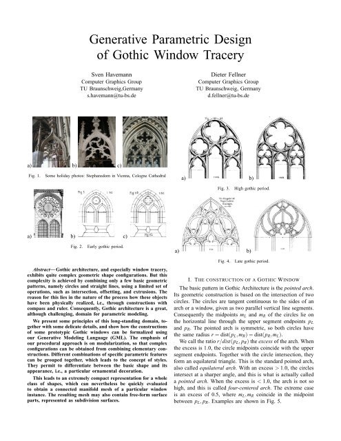
Fig. 3. High gothic period.<br />
a) b)<br />
Fig. 4. Late gothic period.<br />
I. THE CONSTRUCTION OF A GOTHIC WINDOW<br />
The basic pattern in <strong>Gothic</strong> Architecture is the pointed arch.<br />
Its geometric construction is based on the intersection <strong>of</strong> two<br />
circles. The circles are tangent continuous to the sides <strong>of</strong> an<br />
arch or a window, given as two parallel vertical line segments.<br />
Consequently the midpoints mL and mR <strong>of</strong> the circles lie on<br />
the horizontal line through the upper segment endpoints pL<br />
and pR. The pointed arch is symmetric, so both circles have<br />
the same radius r = dist(pL,mR) = dist(pR,mL).<br />
We call the ratio r/dist(pL, pR) the excess <strong>of</strong> the arch. When<br />
the excess is 1.0, the circle midpoints coincide with the upper<br />
segment endpoints. Together with the circle intersection, they<br />
form an equilateral triangle. This is the standard pointed arch,<br />
also called equilateral arch. With an excess > 1.0, the circles<br />
intersect at a sharper angle, and this is what is actually called<br />
a pointed arch. When the excess is < 1.0, the arch is not so<br />
high, and this is called four-centered arch. The extreme case<br />
is an excess <strong>of</strong> 0.5, where mL,mR coincide in the midpoint<br />
between pL, pR. Examples are shown in Fig. 5.
a)<br />
pL<br />
mL<br />
pR<br />
b)<br />
pL<br />
Fig. 5. <strong>Gothic</strong> arch with varying excess parameters: Four-centered (0.75),<br />
equilateral (1.0), and pointed arch (1.25)<br />
pR<br />
mL<br />
a) b)<br />
Fig. 6. The height <strong>of</strong> a pointed arch can be kept constant even when the<br />
width varies.<br />
A. Historical Development <strong>of</strong> <strong>Window</strong> <strong>Tracery</strong><br />
The pointed arch is a generalization <strong>of</strong> its predecessor,<br />
the round arch. It was a technological breakthrough that,<br />
after its introduction around 1140, has truly revolutionized the<br />
construction <strong>of</strong> cathedrals. It was first systematically employed<br />
by abbot Suger in the cathedral <strong>of</strong> St. Denis (near Paris,<br />
France), and the new style spread over all Europe in just a<br />
few decades. It has dominated the European sacral architecture<br />
for more than two hundred years, and gave rise to a veritable<br />
footrace between cities, where the constructions became ever<br />
more sophisticated and risky.<br />
Technologically, the great advantage <strong>of</strong> the pointed arch<br />
over the round arch lies in the fact that the distance between<br />
columns determines also the height <strong>of</strong> the round arch, whereas<br />
height and width do not have to be equal with the pointed arch<br />
(see Fig. 6). This leaves greater flexibility for positioning the<br />
columns, and helps to solve delicate problems with the design<br />
<strong>of</strong> the ground layout in a cathedral (Fig. 6 right).<br />
Basically the same shape as for an arch can also be used<br />
for a window. The idea <strong>of</strong> <strong>Gothic</strong> cathedrals is to make the<br />
walls <strong>of</strong> the church as transparent as possible, in order to let a<br />
maximum <strong>of</strong> light enter the room. With coloured windows, a<br />
cathedral was flooded with light in all colors, which was one<br />
<strong>of</strong> the manifestations <strong>of</strong> God in the perception <strong>of</strong> the medieval<br />
christian. The size <strong>of</strong> the windows in relation to the size <strong>of</strong> the<br />
walls increased, and the walls actually “dissolved” to the point<br />
where they completely lost their supporting function. <strong>Gothic</strong><br />
cathedrals get their stability almost exclusively from columns,<br />
and not from walls [1].<br />
There is a remarkable development <strong>of</strong> the ornamental decoration<br />
in the upper part <strong>of</strong> the window, the couronnement.<br />
In the Early <strong>Gothic</strong> period, starting around 1140, pairs <strong>of</strong><br />
c)<br />
pL<br />
pR<br />
mL<br />
a)<br />
pL<br />
pM<br />
pR<br />
b)<br />
mR<br />
mLR<br />
mLL<br />
mRR<br />
Fig. 7. Geometry <strong>of</strong> the prototype window<br />
mL<br />
mRL<br />
windows were grouped together, forming an ensemble. But<br />
the windows were created by cutting openings into large stone<br />
plates in the wall. This premature form <strong>of</strong> window tracery<br />
is therefore called plate tracery (Fig. 2). In the High <strong>Gothic</strong><br />
period, from around 1250, the stone parts became ever thinner,<br />
and the windows covered an increasing portion <strong>of</strong> the wall.<br />
The glass windows were set into a network <strong>of</strong> stone bars, and<br />
this is when the basic patterns <strong>of</strong> bar tracery evolved (Fig.<br />
3). The late <strong>Gothic</strong> period, in the 14th and 15th centuries,<br />
saw a great refinement and sophistication <strong>of</strong> window tracery.<br />
The basic patterns were varied over and over again, exhibiting<br />
repeated sub-structures with a high degree <strong>of</strong> self-similarity,<br />
up to the point where the static stone construction appeared to<br />
be actually moving (Fig. 4). One example is the French and<br />
English flamboyant style with its flame symbolics [2].<br />
B. The Prototype <strong>Window</strong><br />
The focus <strong>of</strong> this paper is to demonstrate how the construction<br />
rules for <strong>Gothic</strong> architecture can be mapped to a<br />
parametric modeling language. We chose one basic High<br />
<strong>Gothic</strong> window pattern as our prototype, because it exhibits<br />
the main shape features, the “shape vocabulary”, that was<br />
subsequently refined and varied in the Late <strong>Gothic</strong> period.<br />
This prototype window is shown in Fig. 7. It has two<br />
sub-windows which are also pointed arches. They have the<br />
same form, and most <strong>of</strong>ten also the same excess as the large<br />
pointed arch itself, and so the excess parameter is one highlevel<br />
parameter <strong>of</strong> the window. The particular window shown<br />
has excess 1, so that the midpoints <strong>of</strong> the circular arcs and<br />
the segment endpoints pL, pR coincide. So they are also the<br />
midpoints <strong>of</strong> the circular arcs from the subwindow’s arches.<br />
There is another degree <strong>of</strong> freedom however, as shown in<br />
the right image. In order to increase the space for the rosette in<br />
the top, the sub-windows have been set down. Geometrically,<br />
this is a vertical <strong>of</strong>fset between the midpoints <strong>of</strong> the outer arcs<br />
and those <strong>of</strong> the inner arcs, for example between mL and mLR.<br />
C. Adding a Circular Rosette<br />
Now, given the outer and inner pointed arches, the space<br />
between them can be filled in many different ways, which<br />
is the distinguished feature <strong>of</strong> each window. In early days <strong>of</strong><br />
<strong>Gothic</strong>, this space was quite <strong>of</strong>ten filled with a circular rosette.<br />
Geometrically, the problem is to find midpoint and radius <strong>of</strong><br />
the circle so that it touches the outer and inner arches. First
a) b)<br />
mR<br />
mLR<br />
mC<br />
Fig. 8. Determining the midpoint and radius <strong>of</strong> the rosette’s circle<br />
.<br />
note that the window is symmetric, so the midpoint mC has to<br />
lie on the vertical line through pM. Then consider the set <strong>of</strong><br />
all points that have the same distance from the arcs <strong>of</strong> the subwindows<br />
and the big arcs, for example arcLR and arcR, as in<br />
Fig. 8. The intersection <strong>of</strong> this set with the axis <strong>of</strong> symmetry<br />
gives the midpoint mC <strong>of</strong> the circle for the rosette window.<br />
This set is depicted as a dotted curve in Figure 8. What kind<br />
<strong>of</strong> curve is this? A point m with the same distance from the<br />
circles (mR,rR) and (mLR,rLR) with rL + rLR > dist(mL,mLR)<br />
must be on the outside <strong>of</strong> one circle and inside the other. Consider<br />
m = mC as in Fig. 8, and set r := rR − dist(m,mR). Then<br />
r = dist(m,mLR)−rLR. So the sum dist(m,mR)+dist(m,mLR =<br />
rR − r + r − rLR = rR + rLR is actually independent from m’s<br />
position and thus constant for all points in the set. Consequently,<br />
the dotted curve is an ellipse. It can be computed<br />
as the intersection <strong>of</strong> the axis <strong>of</strong> symmetry and the ellipse<br />
(mR,mLR,rR + rLR). The intersection <strong>of</strong> a line and an ellipse<br />
is the intersection <strong>of</strong> a circle with the corresponding linearly<br />
transformed line.<br />
D. Offset Curves<br />
The rosette circle and the sub-arches partition the window<br />
into disjoint regions. These regions give the basic window<br />
structure, which is then further refined. This can be done by<br />
simply adding a pr<strong>of</strong>ile around the actual window holes to<br />
emphasize the shape, or, especially in the later period, by<br />
adding sub-structures, again composed <strong>of</strong> lines and circular<br />
arcs. It is very common that there is a thin planar border<br />
between adjacent regions, so that there is actually a connected<br />
border plane. Geometrically, this means that the region border<br />
is <strong>of</strong>fset by a certain distance, as depicted in Fig. 9, so that a<br />
contiguous border plane results, shown in yellow.<br />
Regarding the great variety <strong>of</strong> examples where this pattern<br />
is used, it is reasonable to distinguish between two different<br />
<strong>of</strong>fset parameters, namely the interior <strong>of</strong>fset and the <strong>of</strong>fset<br />
distance <strong>of</strong> the ensemble to the outer pointed arch: Both<br />
parameters are equal in Fig. 9 a), while in 9 b) the outer<br />
<strong>of</strong>fset is doubled.<br />
The great thing about the circle is that its <strong>of</strong>fset is again a<br />
circle. This applies also to curves like a pointed arch that are<br />
created from a sequence <strong>of</strong> circular arcs and line segments. But<br />
note that if the sequence contains corners, e.g. two arcs joining<br />
a) b) c)<br />
Fig. 9. a),b) The regions are shrunk to embed them in a common border<br />
plane. c) The <strong>of</strong>fset operation changes the excess <strong>of</strong> a pointed arch, but keeps<br />
the circle midpoints constant.<br />
Fig. 10. Lying and standing trefoil and quatrefoil rosettes.<br />
in an intersection <strong>of</strong> the respective circles, the intersection <strong>of</strong><br />
the <strong>of</strong>fset circles must be computed for obtaining the <strong>of</strong>fset<br />
curve sequence. Simple scaling is not sufficient to create <strong>of</strong>fset<br />
curves: The <strong>of</strong>fset <strong>of</strong> a pointed arch has a different excess than<br />
the original arch, as shown in Fig. 9 c).<br />
E. Rosette <strong>Window</strong> with Multiple Foils<br />
A very common way to fill a circular region is by an<br />
rosette with multiple foils, for example a trefoil or a quatrefoil.<br />
We consider two variants <strong>of</strong> rosettes, namely with round and<br />
with pointed foils. A further distinction is between lying and<br />
a) b)<br />
b<br />
c a<br />
Fig. 11. Construction <strong>of</strong> a rosette with six rounded foils, so α = 2π<br />
6 .<br />
a) b)<br />
α 2 α2<br />
m<br />
m<br />
m ′ m ′′<br />
Fig. 12. Construction <strong>of</strong> a rosette with pointed foils, with a relative<br />
displacement <strong>of</strong> 1.15 to obtain m ′ and m ′′ from m.<br />
b<br />
c<br />
a
a) b)<br />
Fig. 13. Offset operation to obtain the region borders.<br />
a) b)<br />
Fig. 14. Pointed trefoil obtained from pointed arch.<br />
standing rosettes, as shown in Fig. 10.<br />
The geometry is fairly straightforward: Given the number<br />
n <strong>of</strong> foils in a unit circle, the radius r <strong>of</strong> the round foils is<br />
computed as shown in Fig. 11 b). Consider the tangent from<br />
center c to the circle (m,r). The distance from c to m is 1−r,<br />
so the length <strong>of</strong> the perpendicular from m to the tangent is<br />
, which is supposed to be r. This equation gives<br />
(1 − r)sin α 2<br />
r = sin α 2 /(1 + sin α 2 ). The perpendicular feet a and b are the<br />
endpoints <strong>of</strong> the circular arc that is rotated and copied n times<br />
to make up the rosette.<br />
The pointed foils can be obtained from the round foils as<br />
shown in Fig. 12. The midpoints m ′ ,m ′′ are obtained from<br />
m by displacement along the lines (a,m) and (b,m). The<br />
pointedness, and thus the radius <strong>of</strong> the circles, is influenced by<br />
the amount <strong>of</strong> displacement, which can be specified in relation<br />
to the original radius. Points a and b and the intersection point<br />
c then specify the arcs which make up the pointed foils. In<br />
order to fit into the original circle, the foils are scaled: Circles<br />
permit uniform scaling, and so do circular arcs.<br />
Just as described in section I-D, a connected boundary<br />
region is constructed from the network <strong>of</strong> circular arcs. Examples<br />
are shown in Fig. 13. Note that also these <strong>of</strong>fset curves<br />
also only consist <strong>of</strong> arcs and line segments.<br />
F. Further Refinements<br />
Circular arcs can be combined very flexibly. Both corners<br />
and tangent continuous joints can be obtained from quite<br />
elementary geometric constructions. The pointed trefoil in Fig.<br />
14 for instance is easily obtained from a pointed arch: First<br />
both arcs are symmetrically split, and then the lower parts are<br />
replaced each by a pair <strong>of</strong> smaller arcs. Tangent continuity<br />
is obtained by choosing the midpoint <strong>of</strong> the next arc on the<br />
line through mid- to endpoint <strong>of</strong> the given arc. This example<br />
shows the source <strong>of</strong> the great variability <strong>of</strong> geometric patterns<br />
in <strong>Gothic</strong> architecture.<br />
G. Appearance: Pr<strong>of</strong>iles<br />
So far, the structure <strong>of</strong> the window is solely defined by<br />
the different regions, with their closed borders composed <strong>of</strong><br />
a) b)<br />
Fig. 15. <strong>Window</strong> pr<strong>of</strong>iles.<br />
line and circular arc segments. All constructions presented<br />
are solely two-dimensional. The fascinating and impressive<br />
three-dimensionality <strong>of</strong> <strong>Gothic</strong> windows is achieved by pr<strong>of</strong>iles<br />
that give depth to the two-dimensional geometric figures. In<br />
architectural illustrations, pr<strong>of</strong>iles can <strong>of</strong>ten be found above or<br />
below a front view, like those in Fig. 15 from Egle [3].<br />
Technically, these pr<strong>of</strong>iles are swept along the region border<br />
curves, with the pr<strong>of</strong>ile plane being orthogonal to the tangent<br />
<strong>of</strong> the curve. At corner points, where the tangent is discontinuous,<br />
the sweep is continued onto the bisector plane. This is the<br />
plane that is spanned by the bisecting line <strong>of</strong> the angle in the<br />
corner and the normal <strong>of</strong> the 2D construction plane. Actually<br />
this only applies when the curve is locally symmetric to the<br />
bisector plane. In more general cases, the discontinuity locally<br />
follows the medial axis <strong>of</strong> the two parts <strong>of</strong> the curve.<br />
II. GML REALIZATION<br />
The <strong>Generative</strong> Modeling Language (GML) is a very simple,<br />
stack-based programming language for creating polygonal<br />
meshes [4]. The language core is very similar to that <strong>of</strong><br />
Adobe’s PostScript, as concisely described in chapter 3 <strong>of</strong><br />
the PostScript “Redbook” [5], which largely applies also<br />
to the GML. The GML doesn’t have PostScript’s extensive<br />
set <strong>of</strong> operators for typesetting, though. Instead, it provides<br />
quite a number <strong>of</strong> operators for three-dimensional modeling,<br />
from low-level Euler operators for mesh editing, to high-level<br />
modeling tools, such as different forms <strong>of</strong> extrusions, and<br />
operators to convert back and forth between polygons and<br />
mesh faces.<br />
Despite its simplicity, the GML is a full programming<br />
language, and it can be used to efficiently exploit the striking<br />
similarity between 3D modeling and programming: Good,<br />
well-structured 3D modeling <strong>of</strong>ten follows a coarse-to-fine approach<br />
when designing a shape, and well-structured programs<br />
use re-usable parameterized classes or modules to accomplish<br />
any particular instance <strong>of</strong> the type <strong>of</strong> task they have been<br />
designed for.<br />
A. The Pointed Arch<br />
A pointed arch is composed <strong>of</strong> two circular arcs. An arc can<br />
be specified by start- and endpoint, and the midpoint <strong>of</strong> the<br />
circle, like in Fig. 11 b). In GML, we write this as an array <strong>of</strong><br />
three points: [ a m b ]. This alone is ambiguous, as there are
two possible arcs, in clockwise (CW) and in counterclockwise<br />
(CCW) orientations from a to b. So we also specify a normal<br />
vector n and introduce the convention that the arc is always<br />
CCW oriented when seen from above (i.e., when the normal<br />
points to the viewer). Alternatively, an arc could be specified<br />
by midpoint, radius and two angles, or by midpoint, start point<br />
and angle. But this either depends on the orientation <strong>of</strong> the<br />
zero angle axis (i.e. the x-axis), or start and endpoint are not<br />
treated symmetrically.<br />
Now given the circles (mL,r) and (mR,r) as in Fig. 5, the<br />
intersection is computed by an operator that expects midpoints<br />
and radii <strong>of</strong> two circles and the plane normal on the stack:<br />
mL r mR r nrml intersect_circles pop<br />
Every operator simply pops its arguments from the stack,<br />
computes one or more results, and pushes them back on the<br />
stack. In this case, the intersection points above and below the<br />
line between m0 and m1 are pushed on the stack, in this order.<br />
As we’re only interested in the intersection above, the other<br />
result is popped. The remaining point now defines a variable<br />
q, and the two arcs are assembled with just another line <strong>of</strong><br />
code:<br />
/q exch def [ q mL pL ] [ pR mL q ]<br />
B. Creating a Closed Polygon<br />
The resulting two arcs can be seen as a high-level representation<br />
<strong>of</strong> a pointed arch. In order to create a discrete polygonal<br />
mesh, the continuos arcs need to be sampled, i.e. converted to<br />
polygons. This is done by the circleseg operator that expects<br />
an arc, a plane normal vector, an integer resolution and a mode<br />
flag on the stack. As the arc is already there, it is sufficient to<br />
push only the other parameters: nrml 4 1 circleseg leaves<br />
the polygon as an array <strong>of</strong> 4+1=5 points on the stack. To<br />
also convert the other array, the topmost stack elements are<br />
swapped using exch. The two arrays are then concatenated<br />
into one polygon:<br />
nrml 4 1 circleseg exch<br />
nrml 4 1 circleseg arrayappend<br />
The arrayappend operator yields [arr1][arr2] → [arr1arr2].<br />
But note that the order is always very crucial when operating<br />
on the stack: The arcs were pushed in order left, right, so that<br />
they could be processed right, left. This way, a combined CCW<br />
oriented polygon can be created. But note that it contains the<br />
tip <strong>of</strong> the arch twice, as it was the last point <strong>of</strong> the right arc<br />
and the first point <strong>of</strong> the left arc. This was done intenionally to<br />
create a corner there (see below). The bottom <strong>of</strong> the arch can<br />
also be created the same way: Suppose bL, bR are the bottom<br />
corners <strong>of</strong> the window, so that (bL,qL) and (bR,qR) are the<br />
left and right vertical line segments. Then the complete code<br />
to create the polygon in Fig. 16 a) looks like this:<br />
mL r mR r nrml intersect_circles pop<br />
/q exch def [ q mL pL ] [ pR mL q ]<br />
[ bL dup bR dup ]<br />
2 { exch nrml 4 1 circleseg arrayappend }<br />
repeat<br />
a) b) c)<br />
Fig. 16. Creation <strong>of</strong> a pointed arch: a) The circular arcs are sampled and<br />
combined into a single outline polygon. b) A double-sided Combined BRep<br />
face is created and then extruded. Sharp edges are shown in red, smooth<br />
edges in green. c) Front and back are sharp faces as their border contains<br />
BSpline curve segments. Quads on the sides are tesselated using Catmull/Clark<br />
subdivision.<br />
The repeat operator expects a number n and a function on<br />
the stack, and simply executes the function n times.<br />
Functions and executable arrays are synonymous in the<br />
GML: The opening brace { puts the interpreter in deferred<br />
mode, and subsequent tokens are not executed but just put on<br />
the stack. The closing } is a signal to create an ordinary array<br />
from these tokens, and to set its executable flag to true. So<br />
this is an executable array, ready to be executed as the loop<br />
body.<br />
C. Creating a Polygonal Mesh<br />
Two very basic modeling operations turn this polygon into<br />
a mesh, as shown in Fig. 16:<br />
5 poly2doubleface (0.0,1.0,5) extrude<br />
The poly2doubleface creates an n-sided face from an<br />
n-sided polygon. It provides different modes to do this. So<br />
in addition to the polygon it expects an integer number on<br />
the stack that specifies how to handle successive identical<br />
points, and whether the face should have smooth or sharp<br />
edges. Mode 5 for example creates sharp edges, and if a point<br />
occurs repeatedly, only a single mesh vertex is created and it<br />
is flagged as corner vertex, whereas the other vertices are set<br />
to crease vertex. This creates two n-sided faces on front and<br />
back, which is topologically a solid, but with zero volume.<br />
The result <strong>of</strong> this operation is one halfedge as a handle on the<br />
stack. Halfedges are an integral data type in the GML.<br />
Besides this halfedge, the extrude operation expects a<br />
3D point (dx,dy,mode) on the stack, where dx specifies the<br />
shrinking and dy the vertical distance <strong>of</strong> the extruded face to<br />
the original face. The mode flag again specifies vertex types<br />
and edge sharpness flags. Mode 5 for example means that<br />
for “vertical” edges (along normal direction) the vertex type<br />
determines the sharpness, and the “horizontal” edges (in the<br />
displaced face plane) are sharp. This is why just the vertical<br />
edges from the three corner vertices are sharp in Fig. 16 b).<br />
This image also shows the halfedge returned by extrude as<br />
the red half-arrow in the lower left.<br />
D. Mesh Representation: Combined BReps<br />
The underlying mesh representation is the Combined BReps<br />
[6], CBRep for <strong>short</strong>. Each CBRep edge carries a sharpness<br />
flag that can be set to either sharp (red) or smooth (green).
a) b) c)<br />
Fig. 17. Creating a window in a wall: a) The arch is inverted by negative<br />
extrusion. The backface (culled, not rendered) is closer and CW oriented<br />
(black halfedge). b) A wall with its front face in the same geometric plane<br />
as the arch’s backface. The backface (black halfedge) is made a ring <strong>of</strong> the<br />
wall’s front face (halfedge at bottom) using the killFmakeRH Euler operator.<br />
c) The tesselation <strong>of</strong> the wall respects the ring just created and trims it out.<br />
These flags determine which tesselation method to use for<br />
a face: Faces that contain one or more smooth edges are<br />
smooth faces. They are treated as Catmull/Clark subdivision<br />
surfaces. Faces with only sharp edges and where all vertices<br />
are corners are treated as polygonal faces. Faces with only<br />
sharp edges but where not all vertices are corners are sharp<br />
faces. The border <strong>of</strong> such a sharp face contains BSpline curves,<br />
but it is triangulated for display just like polygonal faces. An<br />
example is the front face <strong>of</strong> the arch in Fig. 16 c). A vertex<br />
is classified as corner vertex if three or more <strong>of</strong> its edges are<br />
sharp, with exactly two sharp edges it is a crease vertex. So<br />
the classification actually proceeds from edges to vertices to<br />
faces.<br />
Combined BReps have another feature, which is that polygonal<br />
or sharp faces may have rings. A ring is a “negative”,<br />
CW oriented, face in the interior <strong>of</strong> another face, which is the<br />
ring’s baseface. It trims out a hole, which is quite useful e.g.<br />
for creating windows in a façade.<br />
Note that the backface <strong>of</strong> the arch model is actually CW<br />
oriented from the perspective in Fig. 16 c). So one way to<br />
create a hole is by negative extrusion, so that the model<br />
appears inverted when backface culling is active. A halfedge<br />
<strong>of</strong> the backface is obtained using “halfedge navigation”: The<br />
edgeflip operator returns the mate <strong>of</strong> a halfedge, which is<br />
part <strong>of</strong> the neighbour face, and runs in reverse direction. Given<br />
an edge eWall <strong>of</strong> the wall, the backside is turned into a ring <strong>of</strong><br />
the wall using the killFmakeRH Euler operator, which reads<br />
“kill Face, make Ring Hole”:<br />
5 poly2doubleface dup edgeflip exch<br />
(0,-0.3,5) extrude exch eWall killFmakeRH<br />
Here, the halfedge on the front-facing side <strong>of</strong> the doublesided<br />
face is duplicated, and the duplicate is flipped on the<br />
backside. The top two stack elements are exchanged, so that<br />
the negative extrusion <strong>of</strong> -0.3 units operates on the front face<br />
and pushes it farther away, returning a halfedge <strong>of</strong> the extruded<br />
face. Another exch brings the backside-halfedge again to the<br />
top, and it is made a ring <strong>of</strong> the wall’s front side.<br />
E. The Pointed Arch as a Function<br />
This last example illustrates one <strong>of</strong> the drawbacks <strong>of</strong> the<br />
stack approach: It can be very tedious to keep track <strong>of</strong> the<br />
items and their order. Another option is to use named variables,<br />
a) b) c)<br />
Fig. 18. a) The execution <strong>of</strong> gothic-window yields eight polygons on the<br />
stack defining the structure <strong>of</strong> the prototype window. b) The seven interior<br />
polygons are embedded in the face created from the outer arch. c) Simple<br />
negative etrusion <strong>of</strong> the interior regions.<br />
as in /nrml (0,0,1) def, that are stored in dictionaries –<br />
but searching through the dictionary stack can be slow. As<br />
an alternative, we have introduced named registers. A fixed<br />
number (currently 100) <strong>of</strong> registers can be used between a<br />
beginreg ··· endreg pair. Values can be set using !myvar<br />
and retrieved using :myvar, which is actually even faster than<br />
a push or pop on the stack. This enables a more “procedural”<br />
programming style, while still retaining the flexibility <strong>of</strong> the<br />
stack for passing parameters between functions. As an example<br />
consider the following parameterized version <strong>of</strong> the pointed<br />
arch, now formulated as a function pointed-arch:<br />
beginreg !nrml !<strong>of</strong>fset !excess !pR !pL<br />
:pR :pL :excess line_2pt !mR<br />
:pL :pR :excess line_2pt !mL<br />
:pR :mR dist :<strong>of</strong>fset sub !r<br />
:mL :r :mR :r :nrml intersect_circles pop !q<br />
[ :q :mL :pL :pR :<strong>of</strong>fset move_2pt ]<br />
[ :pR :pL :<strong>of</strong>fset move_2pt :mR :q ]<br />
endreg<br />
The line_2pt function just computes pR +excess(pL − pR),<br />
which results in pL as the midpoint mR <strong>of</strong> the right arch when<br />
the excess is 1.0. The radius <strong>of</strong> the circles is then given by the<br />
distance from pR to mR, minus the desired <strong>of</strong>fset, <strong>of</strong> course.<br />
Now the intersection q <strong>of</strong> the circles left to the line from<br />
mL to mR can be computed. Finally, the two circular arcs are<br />
assembled: The move_2pt operator moves a point into the<br />
direction <strong>of</strong> another point by a specified amount <strong>of</strong> units. Note<br />
that the start point <strong>of</strong> the right and the end point <strong>of</strong> the left<br />
arcs, i.e. the basis points, are computed “inline”: An open<br />
bracket [ is just a literal symbol that is put on the stack, and<br />
the closed ] just makes the interpreter create an array from<br />
all stack elements until it finds the [.<br />
The family <strong>of</strong> pointed arches in Fig. 9 c) was created using<br />
this function by varying the <strong>of</strong>fset parameter.<br />
F. The Prototype <strong>Window</strong> in GML<br />
The GML representation <strong>of</strong> the prototype <strong>Gothic</strong> window is<br />
<strong>of</strong> course a function gothic-window that expects the essential<br />
parameters as described in section I-B on the stack: The left<br />
and right base points <strong>of</strong> the arch, the height <strong>of</strong> the vertical<br />
segments <strong>of</strong> the lower part <strong>of</strong> the window, the excess <strong>of</strong> the<br />
arch, the plane normal, the vertical <strong>of</strong>fset <strong>of</strong> the sub-arches<br />
(cf. Fig. 7), and the outer and inner border thicknesses. The
following call produces the eight polygons that are shown in<br />
Fig. 18 a) together with the wall from before:<br />
(-1,0,2) (1,0,2) 4.0 1.25 (0,-1,0) 0.2 0.1 0.05<br />
gothic-window<br />
This function uses only operators and techniques that were<br />
presented so far. The only additional operator needed is<br />
intersect_line_ellipse, to compute the midpoint <strong>of</strong> the<br />
circle in the top from two points specifying the line, the two<br />
focal points <strong>of</strong> the ellipse, and its radius.<br />
The computation <strong>of</strong> the four fillets, each composed <strong>of</strong> three<br />
arcs, is done explicitly: The start-, mid-, and endpoints <strong>of</strong> each<br />
arc are uniquely defined by the intersection <strong>of</strong> circles. Those<br />
are derived from the big arch, the sub-arches, and the circle,<br />
based on the inner and outer border thicknesses.<br />
G. The Idea <strong>of</strong> a <strong>Window</strong> Style<br />
Executing gothic-window creates eight polygons on the<br />
stack, in a defined order. They can be used to directly create<br />
mesh faces, in a similar manner as in section II-C. But<br />
much more flexibility is gained by introducing the idea <strong>of</strong><br />
window styles – based on the observation that the eight<br />
polygons fall into four groups: Main arch, sub-arches, circle,<br />
and fillets. Instead <strong>of</strong> using gothic-window directly, one can<br />
wrap this into another function gothic-window-style that<br />
subsequently calls four functions corresponding to the four<br />
groups:<br />
beginreg !eBack !eWall<br />
gothic-window<br />
:eWall style-arch !eArch<br />
:eArch :eBack style-circle<br />
2 { :eArch :eBack style-sub-arch } repeat<br />
4 { :eArch :eBack style-fillet } repeat<br />
endreg<br />
What does this function do? First, it expects the same parameters<br />
as gothic-window, and additionally two halfedges,<br />
namely <strong>of</strong> the front- and <strong>of</strong> the backside <strong>of</strong> the wall where<br />
the window is to be inserted. After the polygons are created,<br />
a function style-arch is expected to take the topmost main<br />
arch-polygon from the stack, to somehow insert it into the<br />
wall, and to return a halfedge to the new face. The other items,<br />
the sub-arches, the circle and the fillets, are then inserted into<br />
this main arch face. Each <strong>of</strong> these functions is supposed to<br />
take two halfedges and one polygon from the stack, so that<br />
finally all polygons are popped and processed.<br />
One great thing GML has inherited from Postscript is its<br />
quite flexible name lookup mechanism – namely the dictionary<br />
stack technique. When the GML interpreter encounters an<br />
executable name, such as style-arch, it searches top to<br />
bottom through the current dictionary stack to find the first<br />
dictionary that contains this name as a key. If it exists, the interpreter<br />
takes the corresponding value (literal or executable),<br />
and executes it. The dictionary stack can be freely manipulated<br />
at any time, using begin and end.<br />
So if for example there is a dictionary My-Simple-Style<br />
where all four Style-X keys point to suitable functions, a<br />
particular window instance can be created just like this:<br />
a) b) c)<br />
Fig. 19. a) Pr<strong>of</strong>iles are created by also shrinking an extruded face. b) A simple<br />
horizontal translation <strong>of</strong> the edges can yield self-intersections <strong>of</strong> the surface<br />
c) The more elaborate extrudestable operator removes self-intersections.<br />
a) b) c)<br />
Fig. 20. a) Pr<strong>of</strong>ile used for multiple extrusions. Extrusion starts in the origin<br />
(top left corner); x-direction defines shrinking <strong>of</strong>fset, y-direction pushes into<br />
the wall. b) Shape created by sweeping the pr<strong>of</strong>ile along the border <strong>of</strong> a ring.<br />
c) View more from above.<br />
My-Simple-Style begin<br />
(-1,0,2) (1,0,2) 4.0 1.25 (0,-1,0) 0.2 0.1 0.05<br />
gothic-window-style<br />
end<br />
H. Adding Pr<strong>of</strong>iles<br />
The simple extrude operator used so far can also be used<br />
to shrink the extruded face. This is done by a simple horizontal<br />
<strong>of</strong>fset, translating each edge to the left (i.e. towards the face<br />
interior) by a specified amount <strong>of</strong> units. This works well in<br />
most cases (Fig. 19 a), but it can lead to self-intersections in<br />
faces with sharp corners, such as the central fillet, see 19 b).<br />
We have therefore added a more sophisticated extrudestable<br />
operator, based on the straight line skeleton, which is related<br />
to the medial axis <strong>of</strong> a polygon [7]. This operator not only<br />
removes self-intersections, it can also handle multiple extrudeoperations<br />
at a time, i.e., an array <strong>of</strong> (dx,dy,mode) triplets.<br />
This essentially defines a pr<strong>of</strong>ile, see Fig. 20 for an example.<br />
III. RESULTS<br />
We have carried out a number <strong>of</strong> experiments to test the<br />
variability <strong>of</strong> our style library, some <strong>of</strong> which are shown in<br />
Fig. 21.<br />
In 21 a) only the basic structure is used, and the same pr<strong>of</strong>ile<br />
is used for fillets, circles and sub-arches. The openings are<br />
created by negative extrusion until the backside <strong>of</strong> the wall<br />
is reached, and then the extruded face is made a ring <strong>of</strong> the<br />
backside. In 21 b), the circle style is set to contain a rounded<br />
rosette, but with the same pr<strong>of</strong>ile as before. In the next model<br />
21 c), we switch to pointed foils in the rosette and to a more<br />
elaborate pr<strong>of</strong>ile (the one from Fig. 20). The model Fig. 21 d)<br />
has the same structure as the one before, but a different pr<strong>of</strong>ile,<br />
the number <strong>of</strong> foils is set to 4, and the sub-arches use a pointed
trefoil (cf. Fig. 14). The next model 21 e) shows the same<br />
window with a different pr<strong>of</strong>ile just for the sub-arches, and<br />
another set <strong>of</strong> parameters for the pointed trefoil.<br />
The next example, Fig. 21 f), is actually quite interesting:<br />
This time we use the fillets and the rosette from 21 c), and<br />
combine them with the style from 21 d) as the style <strong>of</strong> the<br />
sub-arches. So we can make use <strong>of</strong> the somewhat recursive<br />
structure <strong>of</strong> <strong>Gothic</strong> architecture, where the sub-arches are<br />
pointed arches just like the outer arch, and consequently permit<br />
the same type <strong>of</strong> refinement. The next two images show one<br />
further iteration: First a style with 21 c) in both sub-arches<br />
(21 g), and then this new style is again used for the sub-arches<br />
(21 h).<br />
At the second refinement level <strong>of</strong> this model, the extrudestable<br />
operator has to remove quite a bit <strong>of</strong> selfintersections<br />
that would otherwise destroy the model, as can<br />
be seen in 21 i). This is due to the fact that in this style<br />
the pr<strong>of</strong>ile, which is essentially a 2D polygon, is uniformly<br />
scaled by an amount depending on the wall thickness. Fig.<br />
21 j) shows the tesselation and gives an idea <strong>of</strong> the number <strong>of</strong><br />
triangles that are created by the subdivision surfaces (about 7<br />
million, after 3 subdivision steps).<br />
The final example 21 k) marks one area <strong>of</strong> future work:<br />
Given an image <strong>of</strong> a window like in 21 l), how well can we actually<br />
reproduce the existing shape? And could there be ways<br />
to determine some <strong>of</strong> the shape parameters automatically?<br />
It should be mentioned that the complete GML code for all<br />
examples, styles, and the library <strong>of</strong> basic <strong>Gothic</strong> window tools<br />
such as pointed-arch, rosette, etc. fits into an ascii file <strong>of</strong><br />
27KB. Building the most complicated example window, 21 h),<br />
takes not much more than a second on a state-<strong>of</strong>-the-art PC.<br />
An interactive GML demo can be downloaded from the<br />
GML website [4] for verification – and for enjoying <strong>Gothic</strong><br />
window tracery, <strong>of</strong> course.<br />
REFERENCES<br />
[1] Binding, Hochgotik. Taschen Verlag, Cologne, Germany, 2002.<br />
[2] ——, Masswerk. Wiss. Buchgesellschaft, Darmstadt, Germany, 1989.<br />
[3] von Egle and Fiechter, Gotische Baukunst, reprint from 1905 ed., ser.<br />
Baustil- und Bauformenlehre. Verlag Th. Schäfer, Hannover, Germany,<br />
1996, vol. Bd. 3.<br />
[4] Havemann. (2003, Aug.) The gml homepage. [Online]. Available:<br />
http://graphics.tu-bs.de/gml<br />
[5] Adobe Systems Inc., PostScript Language Reference Manual, 3rd ed.<br />
Addison-Wesley, 1999.<br />
[6] Havemann and Fellner, “Progressive combined breps – multi-resolution<br />
meshes for incremental real-time shape manipulation,” Computer Graphics<br />
Forum, submitted for publication, also available as technical report<br />
TUBSCG-2003-01, Institute <strong>of</strong> ComputerGraphics, TU at Brunswick,<br />
Germany.<br />
[7] Eppstein and Erickson, “Raising ro<strong>of</strong>s, crashing cycles, and playing<br />
pool: Applications <strong>of</strong> a data structure for finding pairwise interactions,”<br />
Discrete & Computational Geometry, vol. 22, no. 4, pp. 569–592, 1999.<br />
[Online]. Available: http://compgeom.cs.uiuc.edu/˜jeffe/pubs/cycles.html
a) b) c)<br />
d) e) f)<br />
g) h) i)<br />
j) k) l)<br />
Fig. 21. Results. Yop.