High Strength Steel Stamping Design Manual - Auto/Steel Partnership
High Strength Steel Stamping Design Manual - Auto/Steel Partnership
High Strength Steel Stamping Design Manual - Auto/Steel Partnership

You also want an ePaper? Increase the reach of your titles
YUMPU automatically turns print PDFs into web optimized ePapers that Google loves.
Section 3 – Die Process Planning Guidelines for <strong>High</strong> <strong>Strength</strong> <strong>Steel</strong>s<br />
WORK TRAVEL<br />
UPR. PAD<br />
LOCK<br />
STEP<br />
LWR. PAD<br />
POST<br />
AIR, NITROGEN OR<br />
HYDRAULIC CYLINDERS<br />
(NOT TO SCALE)<br />
UPR.<br />
PAD<br />
Page 36<br />
FINISH<br />
TRIM<br />
LWR. PAD<br />
WORK TRAVEL<br />
LWR. PAD<br />
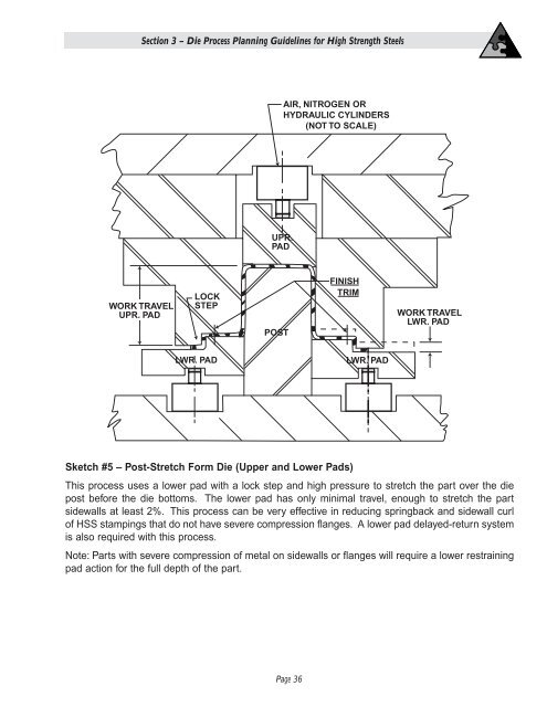
Sketch #5 – Post-Stretch Form Die (Upper and Lower Pads)<br />
This process uses a lower pad with a lock step and high pressure to stretch the part over the die<br />
post before the die bottoms. The lower pad has only minimal travel, enough to stretch the part<br />
sidewalls at least 2%. This process can be very effective in reducing springback and sidewall curl<br />
of HSS stampings that do not have severe compression flanges. A lower pad delayed-return system<br />
is also required with this process.<br />
Note: Parts with severe compression of metal on sidewalls or flanges will require a lower restraining<br />
pad action for the full depth of the part.