

The Autonomous Redundant Navigation System of an AUV for Mine ...
The Autonomous Redundant Navigation System of an AUV for Mine ...
The Autonomous Redundant Navigation System of an AUV for Mine ...

Create successful ePaper yourself
Turn your PDF publications into a flip-book with our unique Google optimized e-Paper software.
<strong>The</strong> <strong>Autonomous</strong> <strong>Redund<strong>an</strong>t</strong> <strong>Navigation</strong> <strong>System</strong> <strong>of</strong> <strong>an</strong> <strong>AUV</strong> <strong>for</strong> <strong>Mine</strong> Counter Measures<br />
Mikael Bliksted Larsen<br />
ATLAS MARIDAN ApS<br />
Agern Allé 3, DK-2970 Hoersholm, Denmark<br />
MBL@marid<strong>an</strong>.dk, +45 45 76 40 50<br />
Abstract<br />
This paper presents the MARPOSII navigation system <strong>of</strong> the SEA OTTER MK2 <strong>AUV</strong>. ATLAS MARIDAN<br />
ApS, Denmark <strong>an</strong>d ATLAS ELEKTRONIK GmbH, Germ<strong>an</strong>y are developing SEA OTTER MK2 as a demonstrator<br />
<strong>Mine</strong> Counter Measures (MCM) <strong>AUV</strong> <strong>for</strong> the Germ<strong>an</strong> Navy. MARPOSII is a state-<strong>of</strong>-the-art <strong>AUV</strong> navigation<br />
system, the second in a series <strong>of</strong> real-time embedded solutions derived from the NAVBOX generic Aided<br />
Inertial <strong>Navigation</strong> <strong>System</strong> (AINS) simulation <strong>an</strong>d post-processing tool.<br />
<strong>The</strong> AINS concept <strong>an</strong>d real-time embedded implementation is briefly described. <strong>The</strong> main emphasis <strong>of</strong> the paper<br />
is on the specific MCM <strong>AUV</strong> functionality: E.g. accurate <strong>an</strong>d fully autonomous navigation with built in redund<strong>an</strong>cy<br />
in algorithms, s<strong>of</strong>tware <strong>an</strong>d hardware. Capability <strong>of</strong> "Synthetic Long Baseline" (Synthetic LBL, pat. pending)<br />
<strong>an</strong>d "Simult<strong>an</strong>eous Localisation And Mapping" (SLAM) systems <strong>for</strong> bounded long-term covert navigation<br />
<strong>an</strong>d relocation are presented. <strong>System</strong>s <strong>an</strong>d concepts are illustrated using data from commercial <strong>AUV</strong> operations<br />
<strong>an</strong>d recent results from the NATO Underwater Research Centre (NURC) - MX3 <strong>AUV</strong> mine hunting operation.<br />
1 Introduction<br />
AINS (Aided Inertial <strong>Navigation</strong> <strong>System</strong>) is a core<br />
technology behind the successful practical use <strong>of</strong><br />
<strong>Autonomous</strong> Underwater Vehicles (<strong>AUV</strong>'s). AINS<br />
makes use <strong>of</strong> a powerful Kalm<strong>an</strong> filter to combine<br />
self-contained inertial navigation with measurements<br />
from external (aiding) sensors. Very import<strong>an</strong>t synergy<br />
arises from statistically optimum integration <strong>of</strong><br />
sensors with complementary characteristics: Automatic<br />
sensor calibration <strong>an</strong>d gyrocompass determination<br />
<strong>of</strong> geographic heading are natural parts <strong>of</strong> the<br />
Kalm<strong>an</strong> filter operation. <strong>The</strong> underlying AINS algorithms<br />
have <strong>an</strong> inherently modular structure leading<br />
to freedom in choice <strong>of</strong> vehicle sensor configuration.<br />
Furthermore, the power <strong>an</strong>d flexibility <strong>of</strong> AINS facilitate<br />
the realisation <strong>of</strong> unconventional navigation<br />
concepts such as Synthetic LBL 1 <strong>an</strong>d "Simult<strong>an</strong>eous<br />
Localisation And Mapping" (SLAM) - a practical<br />
demonstration is given using real-world <strong>AUV</strong> data.<br />
ATLAS MARIDAN has +10 years practical experience<br />
implementing <strong>an</strong>d operating state-<strong>of</strong>-the-art<br />
autonomous navigation systems. Using the MARPOS<br />
[1] <strong>an</strong>d Synthetic LBL [2, 3] navigation systems,<br />
ATLAS MARIDAN <strong>AUV</strong>s have successfully completed<br />
>300 commercial survey operations to date.<br />
Customer De Beers Marine, South Africa, is conducting<br />
routine autonomous surveys that consistently<br />
provide < 1.0 meter absolute navigation accuracy.<br />
Typical Doppler-inertial dead-reckoning per<strong>for</strong>m<strong>an</strong>ce<br />
achieved by their two 2 ATLAS MARIDAN <strong>AUV</strong>s is<br />
reported to be ~ 1.0 meter/hour.<br />
1 Synthetic Long Baseline (SLBL), pat. pending.<br />
2 De Beers Marine received their second ATLAS<br />
MARIDAN <strong>AUV</strong> in May 2006.<br />
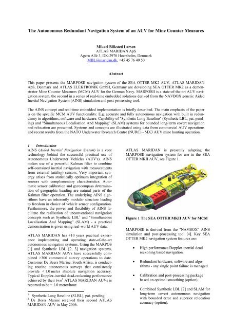
ATLAS MARIDAN is presently adapting the<br />
MARPOSII navigation system <strong>for</strong> use in the SEA<br />
OTTER MKII <strong>AUV</strong>, see Figure 1.<br />
Figure 1 <strong>The</strong> SEA OTTER MKII <strong>AUV</strong> <strong>for</strong> MCM<br />
MARPOSII is derived from the "NAVBOX" AINS<br />
simulation <strong>an</strong>d post-processing tool [4]. Key SEA<br />
OTTER MK2 navigation system features are:<br />
• High per<strong>for</strong>m<strong>an</strong>ce Doppler-inertial dead<br />
reckoning based navigation.<br />
• <strong>Redund<strong>an</strong>t</strong> hardware, s<strong>of</strong>tware <strong>an</strong>d algorithms<br />
- <strong>an</strong>y single point failure is m<strong>an</strong>aged.<br />
• Calibration <strong>an</strong>d post-processing package<br />
based on optimal smoothing (option).<br />
• Combined Synthetic LBL [2] <strong>an</strong>d SLAM <strong>for</strong><br />
long-term covert autonomous navigation<br />
with bounded error <strong>an</strong>d superior relocation<br />
accuracy (option).
MARPOSII further includes <strong>an</strong> accurate time system.<br />
Drift is < 0.1s per 24 hours <strong>of</strong> submerged operation<br />
<strong>an</strong>d proven
Recent applications <strong>of</strong> NAVBOX include:<br />
• Extremely high per<strong>for</strong>m<strong>an</strong>ce navigation in<br />
support <strong>of</strong> Synthetic Aperture Sonar (SAS)<br />
detection <strong>of</strong> buried mines. Germ<strong>an</strong> MJ2000<br />
project [9], see also Figure 4.<br />
• NATO Naval Undersea Research Centre<br />
(NURC) MX3 <strong>AUV</strong> MCM trials, Nov.<br />
2005, La Spezia, Italy.<br />
• NATO harbour protection trials, 2006, La<br />
Spezia.<br />
Figure 4 MJ2000: Synthetic Aperture Sonar<br />
(SAS) <strong>for</strong> buried mine detection - the first<br />
real-time navigation application derived from<br />
NAVBOX.<br />
Some <strong>of</strong> the NAVBOX supported <strong>AUV</strong> sensors <strong>an</strong>d<br />
aiding techniques are:<br />
• IMU<br />
• GPS (or GNSS)<br />
• DVL<br />
• Pressure depth<br />
• USBL<br />
• Fluxgate compass<br />
• ZUPT (Zero velocity update)<br />
• Combined Synthetic LBL <strong>an</strong>d SLAM.<br />
NAVBOX sensor models, simulation <strong>an</strong>d Kalm<strong>an</strong><br />
filter designs are validated <strong>an</strong>d refined through processing<br />
<strong>of</strong> large amounts <strong>of</strong> experimental data. Additional<br />
sensors <strong>an</strong>d navigation techniques are easily<br />
integrated.<br />
2.1 NAVBOX AINS core<br />
NAVBOX includes <strong>an</strong> accurate implementation <strong>of</strong><br />
the AINS algorithms:<br />
• Inertial navigation equations.<br />
• Kalm<strong>an</strong> filter (modular).<br />
• Optimal smoother.<br />
<strong>The</strong> algorithms are org<strong>an</strong>ized as shown in Figure 5.<br />
Each module is explained hereafter.<br />
Figure 5: Aided Inertial <strong>Navigation</strong> <strong>System</strong> Block-<br />
Diagram<br />
Inertial navigation is per<strong>for</strong>med by (correct) integration<br />
<strong>of</strong> measurements from <strong>an</strong> Inertial Measurement<br />
Unit (IMU). <strong>The</strong> Kalm<strong>an</strong> filter integrates in<strong>for</strong>mation<br />
from aiding sensor measurements <strong>an</strong>d applies estimated<br />
navigation error (corrections) to the inertial<br />
navigation.<br />
2.1.1 Inertial Measurement Unit (IMU)<br />
<strong>The</strong> inertial measurement unit (IMU) consists <strong>of</strong> orthogonal<br />
triads <strong>of</strong> gyros <strong>an</strong>d accelerometers. Modern<br />
IMUs generally make use <strong>of</strong> a strap-down configuration<br />
where the IMU sensors are strapped rigidly onto<br />
the vehicle body - no gimbals. An IMU outputs<br />
ch<strong>an</strong>ge in velocity <strong>an</strong>d ch<strong>an</strong>ge in attitude, <strong>of</strong>ten referred<br />
as delta v's (ΔV's) <strong>an</strong>d delta θ's (Δθ's). IMU<br />
data output frequency is typically 100-3000Hz.<br />
IMU's r<strong>an</strong>ge in per<strong>for</strong>m<strong>an</strong>ce from low cost MEMS<br />
devices to state-<strong>of</strong>-the-art Ring Laser Gyro (RLG) or<br />
Fibre Optic Gyro (FOG) based systems.<br />
2.1.2 Inertial <strong>Navigation</strong> Equations (INE)<br />
<strong>The</strong> inertial navigation block implements the<br />
strap-down inertial navigation equations: Position,<br />
orientation <strong>an</strong>d velocity are computed by dead reckoning<br />
from initial conditions using Δθ's <strong>an</strong>d ΔV's<br />
output by the IMU. Pure inertial navigation degrades<br />
with time. To maintain accuracy the inertial navigation<br />
block receives corrections computed by the<br />
Kalm<strong>an</strong> filter. This configuration is referred to as
tightly coupled or closed loop. <strong>The</strong> inertial navigation<br />
equations make use <strong>of</strong> accurate Earth models<br />
(WGS84) <strong>an</strong>d special models <strong>for</strong> Earths gravity.<br />
2.1.3 AINS Kalm<strong>an</strong> filter<br />
<strong>The</strong> error state Kalm<strong>an</strong> filter (ESKF) processes in<strong>for</strong>mation<br />
from aiding sensors. <strong>The</strong> ESKF estimates<br />
errors in inertial navigation (position, attitude/heading<br />
<strong>an</strong>d velocity) <strong>an</strong>d import<strong>an</strong>t errors in the<br />
IMU <strong>an</strong>d aiding sensors. Feedback correction <strong>of</strong> the<br />
inertial navigation is beneficial because it prevents<br />
linearization errors within the Kalm<strong>an</strong> filter from becoming<br />
signific<strong>an</strong>t. Feedback is particularly import<strong>an</strong>t<br />
when low cost inertial sensors are used (=> large<br />
errors). M<strong>an</strong>y adv<strong>an</strong>ced navigation concepts c<strong>an</strong> be<br />
implemented efficiently via "shrewd" augmentation<br />
<strong>of</strong> the Kalm<strong>an</strong> filter.<br />
2.1.4 Sensor models<br />
<strong>The</strong> Kalm<strong>an</strong> filter makes use <strong>of</strong> sensor models to extract<br />
<strong>an</strong>d optimally weight measurement in<strong>for</strong>mation:<br />
Differences between the expected (sensor model) <strong>an</strong>d<br />
the measured values are used by the Kalm<strong>an</strong> filter to<br />
improve its estimate <strong>of</strong> errors. NAVBOX sensor configuration<br />
<strong>an</strong>d parameter values are user configurable.<br />
2.1.5 Optimal smoothing<br />
Optimal smoothing [6] is a Kalm<strong>an</strong> filter based postprocessing<br />
technique that provides statistically optimum<br />
results 3 . Optimal smoothing uses all past <strong>an</strong>d<br />
future sensor measurements to compute the optimum<br />
navigation solution <strong>for</strong> every time point <strong>of</strong> a mission<br />
(fixed interval smoothing). Note, that optimal<br />
smoothing does NOT low-pass filter or in <strong>an</strong>y other<br />
way degrade the precise high dynamics capability <strong>of</strong><br />
inertial navigation. <strong>The</strong> practical benefit <strong>of</strong> optimal<br />
smoothing is subst<strong>an</strong>tial as shown in section 3. In<br />
support <strong>of</strong> rapid data evaluation, innovative concepts<br />
are in place to reduce post-processing time to <strong>an</strong> insignific<strong>an</strong>tly<br />
small percentage <strong>of</strong> mission time.<br />
2.1.6 Synthetic LBL<br />
Figure 6 illustrate the Synthetic LBL concept [2].<br />
Through ch<strong>an</strong>ge in position <strong>an</strong>d a dead-reckoning capability,<br />
the <strong>AUV</strong> creates synthetic baselines, which<br />
c<strong>an</strong> be used <strong>for</strong> trilateration <strong>of</strong> acoustic r<strong>an</strong>ge<br />
measurements from a single beacon, see Figure 6<br />
(top). In principle, this is much the same as r<strong>an</strong>ge<br />
trilateration in conventional LBL, see Figure 6 (bottom).<br />
NAVBOX uses the power <strong>an</strong>d flexibility <strong>of</strong> its<br />
AINS Kalm<strong>an</strong> filter to implement the Synthetic LBL<br />
concept: <strong>The</strong> state vector is augmented with feature<br />
(beacon) position <strong>an</strong>d initial feature (beacon) position<br />
uncertainty is m<strong>an</strong>aged by assigning proper values to<br />
elements <strong>of</strong> the Kalm<strong>an</strong> covari<strong>an</strong>ce matrix. This arr<strong>an</strong>gement<br />
is referred to as a stochastic map in the<br />
robotics navigation literature. <strong>The</strong> Kalm<strong>an</strong> filter will<br />
3 Certain statistical preconditions apply.<br />
"map" the feature (beacon) as the <strong>AUV</strong> moves<br />
around collecting r<strong>an</strong>ge measurements <strong>an</strong>d since the<br />
Kalm<strong>an</strong> filter knows that the feature is stationary, the<br />
measurements will simult<strong>an</strong>eously prevent further<br />
growth in position error. A practical example using<br />
real-world experimental <strong>AUV</strong> data is given in section<br />
3.<br />
Figure 6 Illustration <strong>of</strong> the Synthetic LBL concept:<br />
Duality between single beacon r<strong>an</strong>ging<br />
combined with dead-reckoning (topmost figure)<br />
<strong>an</strong>d conventional LBL (bottom).<br />
2.1.7 SLAM<br />
Terminology used in the previous section suggests<br />
commonality between SLAM <strong>an</strong>d Synthetic LBL. In<br />
fact, NAVBOX implements Synthetic LBL <strong>an</strong>d<br />
SLAM as a simple common extension to the<br />
NAVBOX AINS Kalm<strong>an</strong> filter. <strong>The</strong> only principal<br />
difference is the nature <strong>of</strong> the processed observations:<br />
R<strong>an</strong>ge observations <strong>for</strong> artificial beacons vs. vehicle<br />
relative feature position <strong>for</strong> natural seabed features.<br />
Using Kalm<strong>an</strong> terminology, this is a simple matter <strong>of</strong><br />
using different observation models dependent on type<br />
<strong>of</strong> observation. Notice that possible prior knowledge<br />
<strong>of</strong> seabed feature position (e.g. a map) may be utilized<br />
via state vector <strong>an</strong>d covari<strong>an</strong>ce matrix initialization.<br />
A practical example using real-world experimental<br />
<strong>AUV</strong> data is given in section 3.
3 NAVBOX processing <strong>of</strong> real <strong>AUV</strong> data.<br />
This section will demonstrate <strong>an</strong>d discuss selected<br />
NAVBOX capabilities by (<strong>of</strong>fline) processing <strong>of</strong> previously<br />
recorded real-world <strong>AUV</strong> data:<br />
• Doppler-inertial dead reckoning<br />
• Synthetic LBL<br />
• SLAM<br />
• Optimal smoothing<br />
3.1 ATLAS MARIDAN M62 <strong>AUV</strong> test in<br />
Skagerak, 28. September 2001<br />
Figure 7 depicts the ATLAS MARIDAN M62 <strong>AUV</strong><br />
vehicle trajectory during testing in Skagerak between<br />
Denmark <strong>an</strong>d Norway (58°N) in 2001. Total mission<br />
time was about 140 minutes. <strong>The</strong> high-quality reference<br />
was a Sonardyne Ltd., UK, LBL acoustic positioning<br />
system accurate to about 3 meters absolute<br />
<strong>an</strong>d ~0.2 meter relative.<br />
Figure 7: ATLAS MARIDAN M62 <strong>AUV</strong> operation<br />
<strong>an</strong>d Trajectory, Skagerak 28. September 2001<br />
Only the seabed part <strong>of</strong> the data set is used (see<br />
Figure 8). Thus, the LBL reference is available at all<br />
times <strong>an</strong>d provides a single consistent reference. For<br />
the sole purpose <strong>of</strong> this demonstration the reference<br />
is considered accurate ~0.2m.<br />
Lat (relative) [m]<br />
-100<br />
-200<br />
-300<br />
-400<br />
3.2 <strong>Navigation</strong> sequence<br />
<strong>The</strong> following navigation sequence is common to the<br />
examples hereafter:<br />
1. Alignment: 5 minute rapid deployment gyrocompass<br />
alignment (using LBL position<br />
reference as GPS substitute).<br />
2. Dive: 3 minute free inertial dive section -<br />
equivalent to a 600 meter fl<strong>an</strong>k speed dive<br />
<strong>of</strong> a SEA OTTER MK2 equivalent <strong>AUV</strong>.<br />
3. Site survey: 2-hour fully autonomous highresolution<br />
site survey.<br />
4. Surfacing: 4 minute free inertial surfacing<br />
(inclusive <strong>of</strong> ~1 minute <strong>for</strong> "GPS" reacquisition).<br />
5. Post-mission alignment: 2 minutes <strong>of</strong><br />
post-mission gyrocompass alignment (using<br />
LBL position reference as GPS substitute).<br />
<strong>The</strong> site survey part <strong>of</strong> the mission is per<strong>for</strong>med using<br />
different navigation strategies:<br />
1. St<strong>an</strong>dalone Doppler-inertial<br />
dead-reckoning.<br />
2. SLAM using three natural seabed features<br />
3. Synthetic LBL using a single beacon with<br />
unknown but stationary position (r<strong>an</strong>ge-only<br />
based SLAM).<br />
Used colours match plots <strong>an</strong>d figures hereafter.<br />
Figure 8 show the four beacon (tr<strong>an</strong>sponder) LBL<br />
array used as reference (black/red diamonds), the<br />
beacon in the centre (red diamond) is used <strong>for</strong> Synthetic<br />
LBL navigation, <strong>an</strong>d three natural features<br />
(green tri<strong>an</strong>gles) are used <strong>for</strong> SLAM.<br />
600<br />
500<br />
400<br />
300<br />
200 Acoustic tr<strong>an</strong>sponder (reference)<br />
100<br />
0<br />
Vehicle trajectory relative Lat: 57.9247384 Lon: 9.49193279<br />
End <strong>of</strong> trajectory<br />
Natural seabed feature (SLAM)<br />
Beacon (Synthetic LBL)<br />
Start <strong>of</strong> trajectory<br />
-800 -600 -400 -200 0 200 400 600<br />
Lon (relative) [m]<br />
Figure 8 Trajectory, reference tr<strong>an</strong>sponders,<br />
natural seabed features <strong>an</strong>d Synthetic LBL beacon.
3.3 <strong>Navigation</strong> results<br />
Figure 9 hereunder show the NAVBOX results. <strong>The</strong><br />
two topmost time series are "real-time" navigation<br />
<strong>an</strong>d the lower time series come from post-processing<br />
by optimal smoothing. Y-axis: "Radial position error"<br />
is the difference between NAVBOX AINS <strong>an</strong>d<br />
the LBL acoustic reference. Y-axis "Quality CEP50 4<br />
[m]" is the Kalm<strong>an</strong> filter / smoother's estimate <strong>of</strong> position<br />
accuracy. Integrity <strong>of</strong> the "real-time" navigation<br />
is confirmed since measured error is quite consistent<br />
with expected CEP50 (dotted lines).<br />
"Real-time" AINS<br />
Optimal smoothing<br />
Figure 9 NAVBOX results, ATLAS MARIDAN<br />
M62 Skagerak 28. September 2001<br />
Several things deserve commenting. <strong>The</strong> discussion<br />
will assume knowledge <strong>of</strong> Kalm<strong>an</strong> filter terminology.<br />
"Real-time" AINS:<br />
<strong>Navigation</strong> error grows during the dive phase<br />
(t =5-8min). When DVL velocity becomes available,<br />
much <strong>of</strong> the dive phase error is recovered - this is due<br />
to correlation between velocity error <strong>an</strong>d position er-<br />
4 CEP50 - Circular Error Probable at 50%, e.g. there<br />
is a 50% ch<strong>an</strong>ce true position is within circle <strong>of</strong> this<br />
radius.<br />
ror maintained within the Kalm<strong>an</strong> covari<strong>an</strong>ce matrix<br />
[6].<br />
As expected, there is no difference between SLAM<br />
<strong>an</strong>d dead-reckoning (DR) navigation until t ~ 115<br />
minutes, when the <strong>AUV</strong> revisits the three seabed features<br />
(see Figure 8). Passing the features a second<br />
time completely removes error accrued during the<br />
site survey <strong>an</strong>d reduce CEP by ~50% to just over 1<br />
meter - this is consistent with the actual position error<br />
(
general provide approximately the same<br />
post-processed accuracy <strong>for</strong> this type <strong>of</strong> mission.<br />
However, the example is a perfect illustration <strong>of</strong> the<br />
superior integrity <strong>of</strong> Synthetic LBL - particularly the<br />
ability to m<strong>an</strong>age degraded dead-reckoning per<strong>for</strong>m<strong>an</strong>ce<br />
in a robust m<strong>an</strong>or.<br />
3.4 NATO Undersea Research Center (NURC)<br />
MX3 <strong>AUV</strong> <strong>Mine</strong> Hunting Exercise.<br />
ATLAS MARIDAN participated in NURC-MX3 trials,<br />
La Spezia, Italy, Nov. 2005 operating the SEA<br />
OTTER MK1 (M600) <strong>AUV</strong> from the research vessel<br />
"Leonardo", see Figure 10.<br />
Figure 10 NURC-MX3 <strong>AUV</strong> <strong>Mine</strong> Hunting Exercise.<br />
Above: NURC vessel "Leonardo".<br />
Below: MBE mosaic <strong>of</strong> trial area using<br />
post-processed <strong>AUV</strong> navigation data.<br />
<strong>The</strong> MBE mosaic above was generated by De Beers<br />
Marine using post-processed <strong>AUV</strong> navigation data.<br />
<strong>The</strong> mosaic is composed <strong>of</strong> data from several <strong>AUV</strong><br />
tracks. No navigation errors are visible despite very<br />
high resolution.<br />
Figure 11 shows the trajectory <strong>of</strong> a multibeam echosounder<br />
(MBE) "super" classification run. Mission<br />
duration was 1.5 hours travelling at about 2.0 m/s.<br />
Depth r<strong>an</strong>ges from 15 to 40 m <strong>an</strong>d the dist<strong>an</strong>ce from<br />
start to end location is approximately 2.5 km.<br />
Figure 11 Multi Beam Echosounder (MBE)<br />
"super" classification run - 9 potential targets in<br />
percentage clear<strong>an</strong>ce trial area revisited.<br />
Figure 12 shows NAVBOX estimated position accuracy.<br />
CEP50 at the end <strong>of</strong> the real-time run is expected<br />
to be ~2.5m. Using optimal smoothing the accuracy<br />
is improved by at least a factor <strong>of</strong> 2 to less<br />
th<strong>an</strong> 1 m. This example illustrates the efficiency <strong>of</strong><br />
smoothing when applied to linear trajectories with<br />
position updates (GPS) at both ends <strong>of</strong> the mission.<br />
Figure 12 Positioning accuracy<br />
Further details <strong>of</strong> recent ATLAS MARIDAN <strong>AUV</strong><br />
operations are given in [8].
4 MARPOSII navigation system <strong>of</strong> the SEA<br />
OTTER MK2 <strong>AUV</strong>.<br />
MARPOSII, the successor <strong>of</strong> MARPOS [1], is the<br />
real-time embedded equivalent <strong>of</strong> the <strong>of</strong>fline<br />
NAVBOX tool. Key features are:<br />
• High per<strong>for</strong>m<strong>an</strong>ce Doppler-inertial dead<br />
reckoning based navigation.<br />
• <strong>Redund<strong>an</strong>t</strong> hardware, s<strong>of</strong>tware <strong>an</strong>d algorithms<br />
- <strong>an</strong>y single point failure is m<strong>an</strong>aged.<br />
• Calibration <strong>an</strong>d post-processing package<br />
based on optimal smoothing (option).<br />
• Combined Synthetic LBL [2] <strong>an</strong>d SLAM <strong>for</strong><br />
long-term covert autonomous navigation<br />
with bounded error <strong>an</strong>d superior relocation<br />
accuracy (option).<br />
4.1 Hardware configuration<br />
• <strong>Navigation</strong> grade IMU (CEPR < 1NMPH)<br />
• DVL: Teledyne RDI Workhorse navigator<br />
• Spread spectrum (wideb<strong>an</strong>d) acoustic tr<strong>an</strong>sceiver:<br />
Sonardyne Ltd. AVTRAK MK2<br />
• Redund<strong>an</strong>cy: Processors, interfaces, power<br />
supply, sensors <strong>an</strong>d algorithms.<br />
• GPS, CTD / SVS, fluxgate, pressure sensor<br />
• OCXO based time system.<br />
Drift < 0.1 second per 24 hours, supported<br />
by GPS 1PPS.<br />
• High per<strong>for</strong>m<strong>an</strong>ce, low power floating point<br />
processor, Figure 13<br />
Figure 13 <strong>Redund<strong>an</strong>t</strong> PowerPC based floatingpoint<br />
processors<br />
It is pl<strong>an</strong>ned to use the ATLAS MARIDAN SEA<br />
OTTER MK1 (M600) <strong>AUV</strong> (Figure 14) owned <strong>an</strong>d<br />
operated by WTD71 in Eckerförde, Germ<strong>an</strong>y <strong>for</strong> further<br />
MARPOSII development <strong>an</strong>d experimental validation.<br />
Figure 14: M63 M600 Type <strong>AUV</strong> Operated by<br />
WTD71, Eckernförde, Germ<strong>an</strong>y<br />
4.2 S<strong>of</strong>tware configuration<br />
• Real-time Kernel.<br />
• Dual processor boards - dual navigation<br />
s<strong>of</strong>tware packages.<br />
• Flexible messaging system <strong>an</strong>d CORBA [7]<br />
support.<br />
5 Summary<br />
<strong>The</strong> power <strong>an</strong>d versatility <strong>of</strong> AINS <strong>an</strong>d the<br />
NAVBOX simulation <strong>an</strong>d post-processing tool were<br />
described. Recorded <strong>AUV</strong> navigation data were used<br />
to give a practical demonstration <strong>an</strong>d detailed discussion<br />
<strong>of</strong> the two "unconventional" navigation concepts<br />
"Synthetic LBL" <strong>an</strong>d SLAM. <strong>The</strong> Synthetic LBL<br />
concept was found to provide superior integrity <strong>an</strong>d<br />
very good autonomous navigation per<strong>for</strong>m<strong>an</strong>ce. <strong>The</strong><br />
efficiency <strong>of</strong> optimal smoothing <strong>for</strong> <strong>of</strong>fline improvement<br />
<strong>of</strong> navigation accuracy was shown <strong>an</strong>d key features<br />
<strong>of</strong> the MARPOSII real-time embedded navigation<br />
system were listed.<br />
<strong>The</strong> solid <strong>an</strong>d versatile basis provided by NAVBOX<br />
<strong>an</strong>d MARPOSII me<strong>an</strong>s that present <strong>an</strong>d future navigation<br />
system requirements will be met.<br />
6 Acknowledgments<br />
<strong>The</strong> NAVBOX AINS simulation <strong>an</strong>d post-processing<br />
tool was developed largely within the <strong>AUV</strong> 2000<br />
project <strong>of</strong> the Germ<strong>an</strong> Federal Office <strong>of</strong> Defence<br />
Technology <strong>an</strong>d Procurement (BWB).<br />
<strong>The</strong> author wishes to th<strong>an</strong>k past <strong>an</strong>d present colleagues<br />
<strong>for</strong> their contributions, first <strong>an</strong>d <strong>for</strong>emost<br />
Morten Soede Nielsen <strong>an</strong>d Per Fogt Nielsen <strong>of</strong><br />
ATLAS MARIDAN <strong>an</strong>d Ursula Hölscher-Höbing <strong>of</strong><br />
ATLAS Elektronik.<br />
<strong>The</strong> author would also like to th<strong>an</strong>k the skilled members<br />
<strong>of</strong> the DeBeers Marine <strong>AUV</strong> team <strong>for</strong> rewarding<br />
co-operation.
7 Literature<br />
[1] Mikael Bliksted Larsen, High Per<strong>for</strong>m<strong>an</strong>ce Doppler-Inertial<br />
<strong>Navigation</strong> - Experimental Results,<br />
In proceedings <strong>of</strong> IEEE Oce<strong>an</strong>s, 2000.<br />
[2] Mikael Bliksted Larsen, Synthetic Long Baseline<br />
<strong>Navigation</strong> <strong>of</strong> Underwater Vehicles, In proceedings<br />
<strong>of</strong> IEEE Oce<strong>an</strong>s, 2000.<br />
[3] Mikael Bliksted Larsen, Methods And <strong>System</strong>s<br />
For Navigating Under Water, patent application<br />
PCT/DK01/00141. 2000/2001.<br />
[4] Mikael B. Larsen, Ursula Hölscher-Höbing,<br />
Aided Inertial <strong>Navigation</strong> <strong>System</strong> Solutions <strong>for</strong> a<br />
Family <strong>of</strong> <strong>AUV</strong>'s <strong>an</strong>d Adv<strong>an</strong>ced Underwater Vehicles,<br />
UDT 2005, Amsterdam.<br />
[5] www.mathworks.com<br />
[6] R.G. Brown <strong>an</strong>d P. Y. C. Hw<strong>an</strong>g, Introduction to<br />
R<strong>an</strong>dom Signals <strong>an</strong>d Applied Kalm<strong>an</strong> Filtering,<br />
Wiley; 3 edition (November 14, 1996), ISBN:<br />
0471128392<br />
[7] CORBA: http://www.omg.org<br />
[8] Tronje Schneider-Pungs, Sea Trials with the<br />
<strong>Autonomous</strong> Underwater Vehicle Sea Otter, proceedings<br />
<strong>of</strong> UDT Europe 2006, Hamburg, Germ<strong>an</strong>y.<br />
[9] Ursula Hölscher-Höbing, Mikael B. Larsen,<br />
<strong>Navigation</strong> systems solutions: Application <strong>for</strong> a<br />
MCM <strong>System</strong> Consisting <strong>of</strong> Guid<strong>an</strong>ce Vessel -<br />
Surface Drone - Remote Underwater vehicle,<br />
proceedings <strong>of</strong> UDT Europe 2006, Hamburg,<br />
Germ<strong>an</strong>y.<br />
© ATLAS MARIDAN ApS – all rights reserved