Standards: Features - Microtronic GmbH
Standards: Features - Microtronic GmbH
Standards: Features - Microtronic GmbH

Create successful ePaper yourself
Turn your PDF publications into a flip-book with our unique Google optimized e-Paper software.
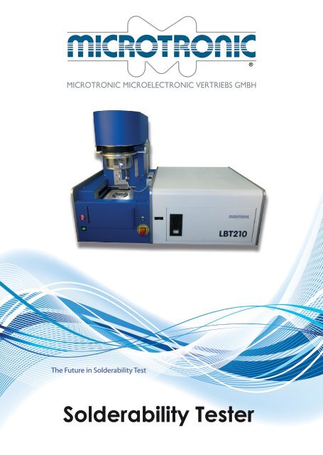
The Future in Solderability Test<br />
Solderability Tester<br />
®
Automated & PC controlled<br />
Solderability Tester<br />
Test Methodes & Options:<br />
• Solder Bath Test with automatic Scraper and Dross Bin<br />
• Solder Ball Test with 1, 2, 3 & 4mm and bucket for used solder balls<br />
• Solder Paste Test with Substrate, Solder paste and your Component<br />
• Automatic testing of multiple Pins<br />
• Automatic testing under Nitrogen Atmosphere<br />
• Tackiness testing (future option)<br />
• Preheating<br />
<strong>Features</strong>:<br />
• Dynamic Range<br />
• Automatic Amplification<br />
• Vibration dampening design<br />
• Brushless DC Servo Motors<br />
• Positioning: better 3µm<br />
• Bath surface position determined by non<br />
contact Laser Sensor<br />
• Video of Measurament can be captured<br />
• E-Stop, CE certified<br />
• Software in German, English, French,<br />
(further languages possible)<br />
• Data saved in a SQL Database with<br />
statistical Analyses<br />
• Export of Data in CSV & Text Files<br />
• Export of Curves as Image Files<br />
<strong>Standards</strong>:<br />
IEC 60068-2-54 & 600068-2-69<br />
IPC/EIA J-STD-003A<br />
IPC7EIC7JEDEC J-STD-002B<br />
EIA/JET-7401<br />
MIL-883 - 2022<br />
We support all commonly<br />
used <strong>Standards</strong>.<br />
Custom standards can be<br />
entered.
Globule Module Bath Module<br />
Solder Paste Module<br />
Easy to use Software.<br />
• Testing galvanized products<br />
• Testing Substrates<br />
• Testing Wetting Forces<br />
• Testing Flux Characteristics<br />
• Testing Paste Characteristics
Why Solderability Test?<br />
One reliable method is to<br />
check components with a<br />
solderability tester. Several international<br />
standards exist for<br />
this method. These systems test<br />
components for solderability,<br />
preferably during incoming<br />
inspection. If the results are<br />
good, the components are<br />
passed on to the production<br />
area. When the results are unacceptable,<br />
the entire lot can<br />
be returned to the manufacturer<br />
or distributor for replacement.<br />
Alternatively, the company<br />
can order from another,<br />
more reliable source before a<br />
lack of components disturbs<br />
production.<br />
If no action is taken to test the<br />
wettability of the components,<br />
the risk is that product will not<br />
pass functional test at the end<br />
of the production cycle because<br />
of bad solder joints. The<br />
defective units need expensive<br />
repairs or they cannot be<br />
reworked. Rejects and field<br />
failures easily can exceed the<br />
investment cost of a solderability<br />
tester.<br />
The Solderability Tester<br />
The solderability test is performed<br />
easily with modern<br />
PC-controlled measurement<br />
equipment. First, all component-relevant<br />
data and test<br />
parameters are placed into<br />
a screenmask. Next, the component<br />
is clamped to a hol-<br />
der and fluxed. The holder is<br />
placed into the tester and<br />
fixed. The test begins and the<br />
system’s software takes all test<br />
data, showing the test curve<br />
together with the data of the<br />
standard norm chosen to determine<br />
solderability. The test<br />
should be performed with approximately<br />
10 sample components<br />
from the same component<br />
lot to provide a mean<br />
value.<br />
<strong>Microtronic</strong>’s LBT-210 solderability<br />
tester has software that<br />
offers statistical information<br />
such as mean value, standard<br />
deviation, etc. A camera option<br />
offers video of the test cycle<br />
and storage in memory with<br />
the appropriate test measurements<br />
and data. Additionally,<br />
it has the feature to test under<br />
nitrogen. This function can be<br />
switched on in the software.<br />
An enclosure that is flooded<br />
with nitrogen lowers and rises<br />
with the device under test.<br />
Measurements<br />
The most common method is<br />
a test using a solder pot filled<br />
with the same alloy that is used<br />
in the production line. Solder<br />
pots are interchangeable<br />
when more than one solder alloy<br />
is in use. The device to be<br />
tested lowers with a defined<br />
speed into the molten solder.<br />
The exact position of the surface<br />
of the solder bath is determined<br />
by non-contact laser<br />
sensor. A scraper removes<br />
all oxidation from the surface<br />
of the molten solder prior to<br />
each test.<br />
Initially, dipping the test specimen<br />
into the molten solder<br />
causes solder displacement<br />
because the test specimen is<br />
at room temperature and the<br />
solder is not wetting the part<br />
yet. The displacement force is<br />
already measured. After the<br />
test specimen has reached<br />
the solder temperature, the<br />
wetting begins. The solder<br />
flows up the test specimen<br />
and the strong surface tension<br />
of the molten solder pulls the<br />
specimen down. These forces<br />
are measured precisely and<br />
are shown in a force-time curve<br />
on the monitor. All previous<br />
time data is available in a listing.<br />
The Software calculates<br />
the measurements and provides<br />
the wetting force or meniscus<br />
angle.<br />
This value can be compared<br />
to the values of other specimens.<br />
The advantage of the<br />
Software is that it compares<br />
the data of earlier (or future)<br />
tests of the same component<br />
from the database to show<br />
a quality trend. A further test<br />
with a molten solder ball,<br />
known as a “globule” test, also<br />
is commonly used. The test sequence<br />
is similar to the solder<br />
pot test. Oxide must be removed<br />
from the molten solder<br />
ball using flux. The test specimen<br />
is placed over the middle<br />
of the globule by motorized X-<br />
and Y-axes. The globule must<br />
be replaced after each test.<br />
Solder particles of different alloys<br />
from 1-4 mm are offered<br />
with the system.<br />
Revolutionary New Test Method<br />
A revolutionary new method<br />
is available that tests using<br />
solder paste and a temperature<br />
profile. A component is<br />
placed on printed solder pas-
te and heated through the<br />
same temperature profile that<br />
is used in production. All force<br />
parameters and values during<br />
the heating cycle are monitored<br />
and saved. This is the<br />
only known existing method<br />
of simulating and qualifying<br />
the solder profile of an in-line<br />
production solder furnace in<br />
conjunction with different solder<br />
pastes and components.<br />
The software is straightforward<br />
and allows the use of comprehensive<br />
component lists. The<br />
appropriate data sets can be<br />
generated, saved and edited<br />
for later use.<br />
As an additional benefit, all<br />
results can be found at any<br />
time and shown in the required<br />
standard norm. Many international<br />
standards are supported<br />
by the system (Figure<br />
2), and custom standards can<br />
be generated and used in the<br />
system easily.<br />
A further function allows the<br />
measurement curve and all<br />
the measurement data to be<br />
exported in other applications.<br />
This function makes it simple to<br />
prepare reports and presentations<br />
(as PDF files that can be<br />
sent via e-mail, etc.). The printout<br />
includes all measurement<br />
parameters, curves and value<br />
listings.<br />
If the system’s computer is<br />
connected to a network, all<br />
test data can be stored on a<br />
central server and retrieved by<br />
individuals. This is significant for<br />
companies that have multiple<br />
locations because all results<br />
can be compared amongst<br />
all users over extended time<br />
periods, further increasing<br />
quality assurance levels.<br />
A measurment cycle<br />
Inserting the Solder Bath<br />
Space for all Modules
The LBT-210’s newly created<br />
software has been designed<br />
for ease of use, allowing users<br />
to start immediately with minimal<br />
effort. After logging in<br />
with a user name and password,<br />
users can select desired<br />
components from the list<br />
and begin testing.<br />
New test specimens can be<br />
integrated easily in the component<br />
list. The same is true<br />
for new testing standards,<br />
users, solder alloys and fluxes.<br />
For an easy overview we<br />
usually display a table with<br />
all information’s for a section.<br />
A double click opens a<br />
window with detailed information<br />
for view or editing.<br />
All information and test data<br />
are saved in a local SQL database.<br />
This ensures all data<br />
is available through progressive<br />
search filters. For ex-<br />
Software<br />
ample, the performance of<br />
component “A” over the last<br />
three years can be determined<br />
within seconds, and<br />
solderability can be compared<br />
in the case of having<br />
the same component from<br />
different suppliers. Results<br />
can be summarized in curves<br />
or the mean value can<br />
be calculated. All standards<br />
have been considered and<br />
the good/bad criteria can<br />
be displayed in the measurement<br />
curves. If required,<br />
videos can be taken<br />
during the measurements<br />
with the built-in Webcam.<br />
Frame rate, sound, CODEC<br />
and more can be adjusted<br />
quickly and easily. To make<br />
the software even easier to<br />
use, a language feature has<br />
been included. Users can<br />
adapt all text fields in the<br />
software in any language.<br />
Additionally, new langua-<br />
ges that are not included<br />
can be added.<br />
Exporting data made simple:<br />
CSV files with the data can<br />
be exported and the curves<br />
can be saved as pictures or<br />
users can use copy & paste.<br />
Results can be printed with a<br />
standard template from our<br />
software or transferred to a<br />
Word template (a WinWord<br />
license is needed for this<br />
function). As an additional<br />
benefit, company-specific<br />
logos, the address and so on<br />
can be included in the document,<br />
enabling professional<br />
reports and analyses to<br />
be printed in a company’s<br />
preferred format. The file<br />
then can be saved, printed<br />
or forwarded digitally to customers.
A Measurment Kurve<br />
Several Results Merged<br />
Setting Test Parameter<br />
Availible Models<br />
The LBT210 system is offered in 4 base versions<br />
LBT-210-100 LBT-210-180 LBT-210-200 LBT-210-300<br />
Lasersensor - X X X<br />
X/Y Table - - X X<br />
Bath Module X X X X<br />
Globule Module - - O X<br />
Paste Module - - O X<br />
Nitrogen Option O O O O<br />
(- = not availible; X = availible; O = optional)<br />
Technical Data Weight: 120 - 145kg<br />
Connections<br />
Volt: 230V<br />
Power: 4A<br />
Nitrogen: 6mm line
The Future in Solderability Test<br />
<strong>Microtronic</strong>s mindset is Creating Value for our<br />
customers in the industries we are serving. Our<br />
deep experience and leadership in core Quality<br />
control technologies leads us in development<br />
and distributing cutting edge equipment.<br />
By permanent improvement, world wide support,<br />
Trainings and tight cooperation with our<br />
customers, we guarantee high quality products<br />
and service.<br />
Local representatives are permantly trained to<br />
give you the best possible support - worlwide.<br />
<strong>Microtronic</strong> <strong>GmbH</strong><br />
Kleingrötzing 1<br />
84494 Neumarkt-Sankt Veit<br />
Tel: +49 8722 9620-0 - Fax: -30<br />
www.microtronic.de<br />
Emai: lbt210@microtronic.de<br />
Your Local Contact:<br />
Copyright <strong>Microtronic</strong> <strong>GmbH</strong> 2010 - Änderungen vorbehalten<br />
®