

MEDIUM VOLTAGE SOFT STARTER TYPE VFS - Mocotech GmbH
MEDIUM VOLTAGE SOFT STARTER TYPE VFS - Mocotech GmbH
MEDIUM VOLTAGE SOFT STARTER TYPE VFS - Mocotech GmbH

You also want an ePaper? Increase the reach of your titles
YUMPU automatically turns print PDFs into web optimized ePapers that Google loves.
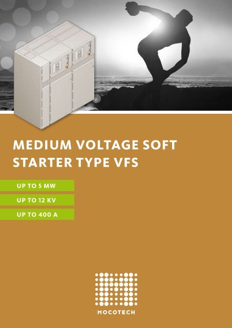
<strong>MEDIUM</strong> <strong>VOLTAGE</strong> <strong>SOFT</strong><br />
<strong>STARTER</strong> <strong>TYPE</strong> <strong>VFS</strong><br />
UP TO 5 MW<br />
UP TO 12 kV<br />
UP TO 400 A
2<br />
MOcOTech<br />
PresenTs The<br />
VAriAble Fre-<br />
qUency sOFT<br />
sTArTer (VFs)<br />
WiTh MAny<br />
UniqUe FeATUres<br />
And AdVAnTAges.<br />
cUsTOMer AdVAnTAges<br />
· Reduction of service and maintenance costs for drives<br />
· Increase of lifetime for drives<br />
· Start / stop with low mechanical stress<br />
· Reduction of starting current<br />
· Minimum voltage drop in the power supply<br />
· Increasing the break away torque of the motors<br />
to be started due to frequency reduction<br />
· Cost saving compact modular design with many options<br />
· Basic design including mains connection,<br />
power electronics, pt, ct and control<br />
· Withdrawable power module with mains contactor,<br />
by pass contactor and power electronics<br />
· HH fuses for reduction of short circuit capacity<br />
· All components with full options in one cabinet only<br />
· Indoor installation<br />
· Operation and maintenance of <strong>VFS</strong> from the front<br />
· <strong>VFS</strong> may be mounted with backside against a wall<br />
· Single or lined up installation<br />
· Cost reduction for lined up installation with<br />
common bus bar<br />
· Bus bar extendable<br />
· Only 1 square meter floor space for each <strong>VFS</strong><br />
· Small incoming cable connection panel (ICCP)<br />
· MV part metal enclosed<br />
· Control part metal clad<br />
· Cable connection from the bottom<br />
· Removable cable entry plates ease the connection<br />
· Service continuity category LSC 2A class PI<br />
· Each thyristor protected with BOD against transient<br />
overvoltage
<strong>MEDIUM</strong> <strong>VOLTAGE</strong> <strong>SOFT</strong><br />
<strong>STARTER</strong> <strong>TYPE</strong> <strong>VFS</strong><br />
TyPe APPrOVed<br />
inTernAl Arc APPrOVed<br />
highesT OPerATOr sAFeTy<br />
highesT AVAilAbiliTy<br />
highesT OPerATiOn sTAbiliTy<br />
drAW OUT POWer MOdUle<br />
UlTiMATe breAk AWAy TOrqUe<br />
3
4<br />
VAriOUs sysTeM Or PrOcess<br />
eFFecTs Will be AVOided:<br />
• Impact in gear teeth<br />
• Impact in couplings<br />
• Vibrations<br />
• Jerky movement of conveyer belts<br />
• Passing critical acceleration speed areas<br />
• Surge (water hammer) problems in pipelines<br />
• Voltage drop in power supply<br />
APPlicATiOn exAMPles<br />
Pump<br />
Fan/Blower/Aerator<br />
Compressor<br />
Chiller<br />
Refiner<br />
Extruder<br />
Centrifuge<br />
Mill Crusher<br />
Hacker<br />
Conveyor<br />
Roller<br />
Rotating converter<br />
Bow thruster<br />
Main propulsion<br />
Water / Waste water<br />
Power generation<br />
Pulp / Paper<br />
Chemical / Petrochemical<br />
Mining<br />
Cement / Stone<br />
Wood processing<br />
Building technology<br />
Marine / Off shore<br />
Industry / Production
OPerATOr sAFeTy<br />
· Internal arc withstand tested acc to IEC 62271 part 200<br />
· Type tested and approved design<br />
· Operation of all components from front with closed doors<br />
· No load switch (NLS) between bus bar and <strong>VFS</strong> equipment<br />
· Isolating plate between open NLS contacts and bus bar provides<br />
a clear visible isolating distance between bus bar and service<br />
parts in <strong>VFS</strong> components<br />
· Earthing switch<br />
· Mechanical interlock between NLS, earthing switch and front door<br />
· Common earthing bus bar<br />
· Cylindrical door lock<br />
· Electrical isolation between LV and MV circuits by use of fibre<br />
optic cable<br />
FUncTiOns<br />
· Soft start<br />
· Soft stop<br />
· Frequency soft start for increase of break away torque<br />
· Active break stop for quick stand still of motor<br />
· DOL start<br />
· Direct stop<br />
· Motor turn function for machines with a long stand by time<br />
· Starting curves: torque / time or current / time freely selectable<br />
· Different starting ramps for pump control<br />
· Dual start adjustment<br />
· Integrated full motor protection features<br />
· Alternative use of standard protection relais possible<br />
· Test with small LV motor<br />
Reduced frequency soft start with sinus wave skip function<br />
provides ultimate breakaway torque with low starting current<br />
(principle diagram)<br />
xx<br />
xx<br />
5
sTArT cUrrenT<br />
liMiTATiOn<br />
(Adjustable max. current)<br />
cUrrenT<br />
TOrqUe<br />
To avoid voltage drop in the power supply,<br />
the starting current can be adjusted to a<br />
pre-set limit. The first chart shows the<br />
starting current. Black graph for DOL<br />
start, coloured graphs for different pre set<br />
maximum currents. The second graph<br />
shows the corresponding torque<br />
characteristics. Extra breakaway torque is<br />
available due to frequency modulation in<br />
the first starting phase. Raised current<br />
limitation results into additional decreased<br />
voltage drop.<br />
6<br />
sPeed<br />
sPeed<br />
sOFT sTArT<br />
(Adjustable max. torque)<br />
TOrqUe<br />
AdjUsTAble<br />
sTArT TiMe<br />
sPeed<br />
sPeed<br />
sTArTing TiMe<br />
The high breakdown torque when starting<br />
a motor DOL (black graph in first chart) can<br />
be avoided.<br />
Therefore a maximum torque during<br />
acceleration is pre-selected (coloured graphs<br />
in first chart). This reduces stress and impact<br />
on the rotating equipment:<br />
motor, coupling, gearbox, driven machine,<br />
etc. Lifetime of machinery increases,<br />
damages are avoided.<br />
A pre-selection of the required starting time<br />
is also possible (second chart).<br />
sPeciAl rAMPs<br />
Example centrifugal pump<br />
start and stop<br />
FlOWrATe<br />
FlOWrATe<br />
sTArTing TiMe<br />
sTOP TiMe<br />
Special acceleration and run down ramps<br />
can be provided for different applications.<br />
For example centrifugal pump control:<br />
Controlled start up avoids damages in pipe<br />
systems due to torque peaks and sudden<br />
pressure increase.<br />
To avoid water hammer effect during pump<br />
stop the run down is controlled in order to<br />
reach a smooth flow reduction. This avoids<br />
excessive noise and damage in the pipe<br />
system (black graphs in the charts for<br />
DOL start and coloured graphs for controlled<br />
pump start / stop). A pre-selection of the<br />
required run down time is also possible.
OPTiOns<br />
· MV cable connection from top<br />
· Incoming cable section right- or backsided<br />
· Customised MV panels attached to same bus bar<br />
· Different stage of completion for MV components inside <strong>VFS</strong> panel.<br />
(see single line diagram page 10)<br />
· Different fixed power factor correction solutions<br />
· Arc pressure release duct<br />
· Remote I/O field housing<br />
· Profibus and Modbus interface<br />
· Many more options. Please consult us with your demands<br />
sTAndArds<br />
· IEC 62271 Part 1 · IEC 62271 Part 102<br />
· IEC 62271 Part 200 · IEC 60470 Part 2000<br />
· IAC AFL 31,5 kA / 1 sec<br />
· Ship classification approval (1)<br />
TechnicAl dATA<br />
Rated voltage kV 7,2 12<br />
Rated current bus bar A … 1850 … 1850<br />
Rated current feeder A …400 (2) …400 (2)<br />
Rated short time current kA …40 …40<br />
Rated peak withstand current kA …100 …100<br />
Rated power frequency withstand voltage kV 20 28<br />
Rated lightning withstand voltage kV 60 75<br />
Operating frequency Hz 45 – 65<br />
Protection class IP IP IP 4X (2)<br />
Site altitude m …1000 (2)<br />
diMensiOns And WeighTs<br />
Rated voltage kV 7,2 12<br />
Height mm 2250 2550<br />
Depth mm 1100 1100<br />
<strong>VFS</strong> (soft starter panel) width mm 900 900<br />
ICCP (incoming cable connection panel) width mm 350 350<br />
ICCP weight kg ...400 ...400<br />
<strong>VFS</strong> weight kg ...1500 ...1500<br />
Explanations: (1) project related / option; (2) higher / more on request<br />
Please ask for our general technical specification (GTS) containing more details.<br />
7
8<br />
READY<br />
LOCAL<br />
FAULT REMOTE STOP<br />
RUN<br />
STOP<br />
HORN<br />
OFF<br />
RUN<br />
DOL<br />
TEST<br />
RESET<br />
reMOTe i/O<br />
MOTOR<br />
TURN<br />
<strong>SOFT</strong><br />
STOP<br />
AUX_A<br />
AUX_B<br />
SET<br />
MENU<br />
/OK<br />
LAMP<br />
TEST<br />
AUX_C<br />
AUX_D<br />
keybOArd<br />
Connection of 8 or 12 REMOTE RTD sensors and up to<br />
12 digital in- and 12 digital output signals to be used for<br />
local control functions at a remote IP 54 connection box<br />
installed beside the drive saving a lot of cabling work.<br />
· High quality and low cost when integrating<br />
the <strong>VFS</strong> into your drive systems.<br />
· Digital microprocessor control with non–<br />
volatile memory and real time clock<br />
· Multi level password access<br />
for operation and parameter<br />
adjustment<br />
· Large illuminated interactive<br />
multi language display with 6 lines<br />
· Metering and indication functions<br />
· 10 LED for status information<br />
· 4 LED for variable use<br />
· Error memory, statistical data and<br />
diagnostic functions<br />
· Standard CAN interface<br />
RTD PCB<br />
1 Left bearing (Machine)<br />
2 Right bearing (Machine)<br />
3 Front bearing (Motor)<br />
4 Motor winding A1<br />
5 Motor winding B1<br />
6 Motor winding C1<br />
7 Back bearing (Motor)<br />
8 Spare<br />
RTD 9-12 Spare<br />
DI+DO 1-12 for local Signals<br />
Can Bus<br />
CPU
m<br />
MiMic diAgrAM<br />
WiTh led POsiTiOn<br />
indicATOrs<br />
A mimic diagram with position<br />
indicators provides clear status<br />
information about the main circuit<br />
to the operator. All position indicators<br />
including the SCR symbols are<br />
LED illuminated.<br />
The LED alternate between red /<br />
green and grey colour for the<br />
various status conditions.<br />
9
single line<br />
1<br />
2<br />
3<br />
4<br />
5<br />
6<br />
7<br />
8<br />
9<br />
10<br />
11<br />
12<br />
13<br />
14<br />
· Lined up <strong>VFS</strong> starter with common<br />
main bus bar<br />
· Individual <strong>VFS</strong> starter for each motor<br />
· Space saving due to small dimensions<br />
· Low price<br />
· Standard panels can be attached<br />
· High availability<br />
10<br />
Incoming panel ICCP (o)<br />
<strong>VFS</strong> panel<br />
Bus bar<br />
ON – OFF no load switch (o)<br />
Earthing switch (o)<br />
Current limiting HH fuses (o)<br />
Earthing bolt<br />
Surge arrestors (o)<br />
Measuring voltage transformer<br />
Measuring current transformer<br />
Mains contactor (o)<br />
By-pass contactor<br />
SCR power stack<br />
Insulation plate (o)<br />
can be inserted from front<br />
This single line is only symbolic and might not be in line<br />
with point of installation for hardware components<br />
(o) = option<br />
Pls consult us if you require other options<br />
insTAllATiOn<br />
AlTernATiVe A<br />
IN<br />
1 2<br />
8<br />
7<br />
M 1 M 2 M 3 M 4<br />
M<br />
3 ~<br />
14<br />
12<br />
5<br />
M<br />
3 ~<br />
3<br />
4<br />
11<br />
9<br />
10<br />
6<br />
M<br />
3 ~<br />
13<br />
3 ~<br />
M<br />
3 ~
IN M 1 M 2<br />
IN<br />
M<br />
3 ~<br />
M<br />
3 ~<br />
M 3 M 4<br />
M<br />
3 ~<br />
M<br />
3 ~<br />
<strong>VFS</strong> 1 M 1 M 2 M 3<br />
M<br />
3 ~<br />
M<br />
3 ~<br />
M<br />
3 ~<br />
insTAllATiOn<br />
AlTernATiVe b<br />
· Stand alone <strong>VFS</strong> starter<br />
· Individual <strong>VFS</strong> Starter for each motor<br />
· Clear motor - starter allocation<br />
· High availability<br />
insTAllATiOn<br />
AlTernATiVe c<br />
· Lined up <strong>VFS</strong> starter with<br />
common main- and aux<br />
starting bus bar<br />
· Several motors share one <strong>VFS</strong><br />
starter<br />
· Individual motor will be<br />
switched to main bus bar after<br />
start up<br />
· Space saving due to small<br />
dimensions<br />
· Low price<br />
11
PrOFile<br />
The first choice for your motor starters should be a company which concentrates on your specific project<br />
requirements, supports you and takes full responsibility for the design and production of your starters.<br />
<strong>Mocotech</strong> realises tailor made solutions based on well proven technologies. We combine flexible solutions<br />
and high quality to implement your individual project goals. Our full attention is on your selected targets<br />
and demands. 60 years experiance in drive technology ensure and guarantee the service availability and<br />
operation stability of your plants.<br />
PrOdUcT<br />
<strong>Mocotech</strong> presents with the <strong>VFS</strong> starter many unique technical features. <strong>Mocotech</strong> is the<br />
first company at the global market which has obtained the IEC 62271-200 type test to meet current<br />
safety demands for MV switchgears and motor starters. You receive at MOCOTECH the highest<br />
value for your drive technology investment.<br />
serVice<br />
Qualified and experienced engineers, take every day the full responsibility for the design, engineering,<br />
production and quality control. We provide after sales services for and training of our customers in our<br />
headquarters at Rheinberg in Germany. Local dealers and agents are available for site support in most areas<br />
around the world.<br />
cOMMiTMenT<br />
We are pleased to serve the steady increasing number of frequent customers who put their trust in our<br />
company. We commit ourselves to produce only reliable and competitive motor starters in top quality. You<br />
can always expect the best from <strong>Mocotech</strong>.<br />
mocotech gmbh Nordring 20 47495 Rheinberg – Germany phone +49 (0)2843 90488-0 fax +49 (0)2843 90488-44<br />
info@mocotech.de www.mocotech.de<br />
0801


