ATP-301 AIR TAPE PRESS Order No. 19228-0030 - Molex
ATP-301 AIR TAPE PRESS Order No. 19228-0030 - Molex
ATP-301 AIR TAPE PRESS Order No. 19228-0030 - Molex

You also want an ePaper? Increase the reach of your titles
YUMPU automatically turns print PDFs into web optimized ePapers that Google loves.
<strong>ATP</strong>-<strong>301</strong> Air Tape Press<br />
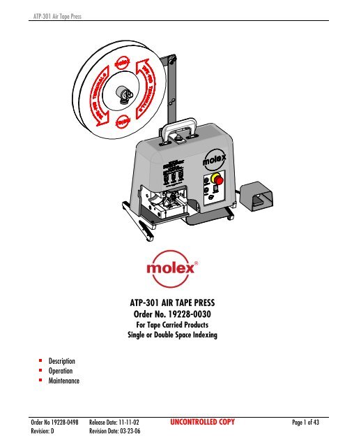
��Description<br />
��Operation<br />
��Maintenance<br />
<strong>ATP</strong>-<strong>301</strong> <strong>AIR</strong> <strong>TAPE</strong> <strong>PRESS</strong><br />
<strong>Order</strong> <strong>No</strong>. <strong>19228</strong>-<strong>0030</strong><br />
For Tape Carried Products<br />
Single or Double Space Indexing<br />
<strong>Order</strong> <strong>No</strong> <strong>19228</strong>-0498 Release Date: 11-11-02 UNCONTROLLED COPY Page 1 of 43<br />
Revision: D Revision Date: 03-23-06
<strong>ATP</strong>-<strong>301</strong> Air Tape Press<br />
WARNING<br />
NEVER USE THIS TOOL WITHOUT GUARDS OR SAFETY DEVICES THAT ARE INTENDED TO PREVENT HANDS FROM REMAINING<br />
IN THE CRIMP TOOLING AREA.<br />
NEVER OPERATE, SERVICE, INSTALL OR ADJUST THIS TOOL WITHOUT PROPER INSTRUCTION AND WITHOUT FIRST READING<br />
AND UNDERSTANDING THE INSTRUCTIONS IN THIS MANUAL AND ALL APPLICABLE <strong>AIR</strong> POWERED CRIMPING TOOL<br />
MANUALS.<br />
NEVER SERVICE THIS MACHINE WHILE IT IS CONNECTED TO ANY ELECTRICAL POWER SOURCE. DISCONNECT POWER BY<br />
UNPLUGGING THE <strong>PRESS</strong> FROM ITS POWER SOURCE.<br />
NEVER INSTALL OR REMOVE CRIMP TOOLING WITH THE <strong>AIR</strong> LINE CONNECTED.<br />
NEVER OPERATE THE <strong>PRESS</strong> WITH <strong>AIR</strong> <strong>PRESS</strong>URE GREATER THAN 110 PSI (AT <strong>PRESS</strong> REGULATOR).<br />
CAUTION MOLEX CRIMP SPECIFICATIONS ARE VALID ONLY WHEN USING MOLEX TERMINALS AND MOLEX APPLICATORS AND<br />
TOOLING.<br />
WORK SAFELY AT ALL TIMES<br />
For Service, Contact Your<br />
Local <strong>Molex</strong> Sales Office<br />
<strong>Molex</strong> Application Tooling Group<br />
2200 Wellington Court<br />
Lisle, IL 60532<br />
Tel: (630) 969-4550<br />
Fax: (630) 505-0049<br />
Visit our Web site at http://www.molex.com<br />
<strong>Order</strong> <strong>No</strong> <strong>19228</strong>-0498 Release Date: 11-11-02 UNCONTROLLED COPY Page 2 of 43<br />
Revision: D Revision Date: 03-23-06
<strong>ATP</strong>-<strong>301</strong> Air Tape Press<br />
1 General Description<br />
2 Installation<br />
3 Setup - Operation<br />
4 Maintenance<br />
Table of Contents<br />
SECTION<br />
5 Parts List, Assembly Drawings, Electrical, Pneumatic and Troubleshooting<br />
<strong>Order</strong> <strong>No</strong> <strong>19228</strong>-0498 Release Date: 11-11-02 UNCONTROLLED COPY Page 3 of 43<br />
Revision: D Revision Date: 03-23-06
<strong>ATP</strong>-<strong>301</strong> Air Tape Press<br />
1.1 Description<br />
1.2 Features<br />
1.3 Technical Specifications<br />
1.4 Delivery Check<br />
1.5 Tools<br />
Section 1<br />
General Description<br />
<strong>Order</strong> <strong>No</strong> <strong>19228</strong>-0498 Release Date: 11-11-02 UNCONTROLLED COPY Page 4 of 43<br />
Revision: D Revision Date: 03-23-06
<strong>ATP</strong>-<strong>301</strong> Air Tape Press<br />
Principal Parts of the <strong>ATP</strong>-<strong>301</strong> Tape Press (<strong>19228</strong>-<strong>0030</strong>)<br />
TOP ROLLER<br />
ASSEMBLY<br />
FRAME<br />
ASSEMBLY<br />
INDEX BLOCK<br />
ASSEMBLY<br />
BASE ASSEMBLY<br />
REEL ARM<br />
ASSEMBLY<br />
Figure 1-1<br />
<strong>PRESS</strong> HANDLE<br />
COVER ASSEMBLY<br />
MAIN <strong>AIR</strong> CYLINDER<br />
ASSEMBLY<br />
RAM ASSEMBLY<br />
LOWER CRIMP<br />
TOOLING ASSEMBLY<br />
CONTROLS<br />
ASSEMBLY<br />
FOOT PEDAL<br />
ASSEMBLY<br />
<strong>Order</strong> <strong>No</strong> <strong>19228</strong>-0498 Release Date: 11-11-02 UNCONTROLLED COPY Page 5 of 43<br />
Revision: D Revision Date: 03-23-06
<strong>ATP</strong>-<strong>301</strong> Air Tape Press<br />
General Descrition<br />
1.1. Description<br />
The <strong>ATP</strong>-<strong>301</strong> (<strong>19228</strong>-<strong>0030</strong>) Air Tape Press is an economical,<br />
electrically controlled, air powered termination machine. It<br />
is designed to provide an effective method for low cost, high<br />
quality terminations of tape carried products including<br />
insulated and uninsulated terminals, quick disconnects, and<br />
some types of splices with sizes from 26 through 8 AWG.<br />
Production flexibility is obtained through the use of<br />
interchangeable crimp tooling. Critical setup and gauging<br />
time is eliminated because of the butting die design built in<br />
to all the <strong>ATP</strong>-<strong>301</strong> crimp tooling. Utilizing this technology<br />
allows changeover of product and tooling in only a few<br />
minutes, regardless of size or style of product.<br />
The <strong>ATP</strong>-<strong>301</strong> Air Tape Press will complete one crimping cycle<br />
with each depression of the foot pedal. A product is<br />
terminated and advanced to the next position for removal in<br />
approximately one second. Double spaced products can be<br />
processed with the flip of a switch.<br />
1.2. Features<br />
��Processes tape carried products including insulated and<br />
uninsulated terminals, quick disconnects and splices<br />
��Double index feature for products double spaced on<br />
tape such as large ring and spade terminals or flag<br />
terminals<br />
��Foot pedal actuation allows hands-free operation<br />
��Versatile, compact, lightweight and portable<br />
��Overhead reel mounting requires less workbench space<br />
��Control panel conveniently located<br />
��Product and tooling changeover in just minutes<br />
��Fast and reliable. Up to 45 cycles per minute<br />
(depending on operator skill)<br />
1.3. Technical Specifications<br />
Dimensions without reel mounted<br />
Height 14.00” (355.6mm)<br />
Width 14.00“ (355.6mm)<br />
Depth 1100” (279.4mm)<br />
Unpacked weight 44 lbs (97 kg)<br />
Shipping weight 52 lbs (115 kg)<br />
Dimensions with 24.00” (609.6mm) reel<br />
mounted<br />
Height 35.00” (889.0mm)<br />
Width 39.75” (1009.6mm)<br />
Tape reel sizes:<br />
14.00” (355.6mm) and<br />
24.00” (635.0mm)<br />
Power Requirements<br />
Voltage: 120V AC, 60 Hz<br />
Production Rate (depending on operator skill)<br />
Single Index: 2800 per hour<br />
Double Index: 2500 per hour<br />
Air Pressure<br />
95-110PSI (At the press)<br />
(6.55/7.58 Bar)<br />
Air Volume<br />
1 Press 1.5 scfm (.00071m 3 /s)<br />
Lubrication Oil<br />
40WT <strong>No</strong>n-detergent<br />
Lubrication Grease<br />
Permatex multi-purpose synthetic grease with Teflon<br />
<strong>No</strong>. 82329<br />
Service Frequency<br />
1 month or 20,000 cycles<br />
Processing Capability<br />
Up to 8 AWG (8.36mm²) of copper conductor in solid or<br />
stranded wire.<br />
Sound Level<br />
Operator will be exposed to less than 85 DB.<br />
<strong>Order</strong> <strong>No</strong> <strong>19228</strong>-0498 Release Date: 11-11-02 UNCONTROLLED COPY Page 6 of 43<br />
Revision: D Revision Date: 03-23-06
<strong>ATP</strong>-<strong>301</strong> Air Tape Press<br />
1.4. Delivery Check<br />
<strong>19228</strong>-<strong>0030</strong> Main press assembly<br />
<strong>19228</strong>-0076 Reel arm assembly<br />
69018-6237 Power cord<br />
63800-8394 Foot pedal assembly (attached)<br />
<strong>19228</strong>-0498 Instruction manual<br />
<strong>19228</strong>-0497 Fastener kit<br />
(Includes 64016-0068<br />
Stripper / Wire stop assembly)<br />
NOTE: See section 2.1 for unpacking instructions.<br />
1.5. Tools<br />
The following tools are recommended for setup and<br />
adjustments to the applicator in this press<br />
1. Standard hex wrench set (inch)<br />
2. Adjustable wrench<br />
3. Wire stripper / cutter<br />
4. Scissors<br />
<strong>Order</strong> <strong>No</strong> <strong>19228</strong>-0498 Release Date: 11-11-02 UNCONTROLLED COPY Page 7 of 43<br />
Revision: D Revision Date: 03-23-06
<strong>ATP</strong>-<strong>301</strong> Air Tape Press<br />
Section 2<br />
Installation<br />
2.1. Unpacking and Positioning the Press<br />
2.2. Reel Arm Assembly Installation<br />
2.3. Air Supply and Electrical Power Connection<br />
2.4. Tape Reel Installation<br />
2.5. Crimp Tooling Installation and Removal<br />
2.6. Insulation Punch Adjustment<br />
2.7. Die Spacer Installation<br />
<strong>Order</strong> <strong>No</strong> <strong>19228</strong>-0498 Release Date: 11-11-02 UNCONTROLLED COPY Page 8 of 43<br />
Revision: D Revision Date: 03-23-06
<strong>ATP</strong>-<strong>301</strong> Air Tape Press<br />
Read the following instructions before attempting to operate tool.<br />
2.1. Unpacking and Positioning the Press<br />
Open the top of the shipping carton. Locate and remove<br />
the reel arm assembly and set aside. Remove the<br />
packaging film and foam as required to gain access to the<br />
air press. Use the press handle to lift the unit out of the<br />
shipping carton. As the press is lifted with one hand,<br />
support the foot pedal assembly with the other and place<br />
the unit on a clean, flat surface. Remove the plastic<br />
covering from around the air press and verify that all items<br />
are present (See delivery check: Section 1.4).<br />
Position the air press on top of a flat, sturdy workbench<br />
approximately 4.00” (100mm) back from the front edge.<br />
Check that the crimping position is ergonomic for the<br />
operator’s size. A bench height of 30.00 to 32.00” (762 to<br />
3/8”-16 THREADED STUD Figure 2-1<br />
813mm) should provide operator comfort and allow both feet to rest on the floor. The foot pedal should be placed in a<br />
comfortable position. A chair or stool with an adjustable height and backrest should be provided for maximum comfort and<br />
back support for the operator.<br />
2.2. Reel Arm Assembly Installation (See Figure 2-1)<br />
1. Remove the 3/8-16” acorn nut and (2) 3/8”<br />
washers from the top cover.<br />
2. Locate the reel arm assembly and disassemble the<br />
cross member by removing (2) 3/8” SHCS.<br />
Reposition the cross member in a horizontal position<br />
extending to the left side with the reel shaft oriented<br />
to the front and replace the (2) 3/8” SHCS and<br />
tighten securely.<br />
3. Place the reel arm assembly over the 3/8-16” stud<br />
on the top of the cover and replace the 3/8-16”<br />
acorn nut and tighten securely. The (2) 3/8”<br />
washers are not required for mounting the reel arm<br />
to the press but may be required for future use if<br />
the reel arm assembly is removed and the press is to<br />
be transported.<br />
REEL SHAFT<br />
<strong>AIR</strong> COUPLING<br />
CROSS MEMBER<br />
<strong>PRESS</strong> HANDLE<br />
<strong>AIR</strong> LINE W/COUPLING<br />
FOOT PEDAL CORD<br />
3/8”-16 SHCS (2)<br />
3/8”-16 ACORN NUT<br />
Figure 2-2<br />
2.3. Air Supply and Electrical Power Connection (See Figure 2-2)<br />
1. Connect the air supply hose to the filter/regulator located on the rear of the press cover. A standard 1/4” NPT quickchange<br />
air coupler compatible with your quick connect brand should be mounted. A 1/4” minimum diameter air hose<br />
should be used to satisfy the 1.5 CFM air volume requirement for the <strong>ATP</strong>-<strong>301</strong>.<br />
2. Connect the appropriate end of the power cord to the socket of the <strong>ATP</strong>-<strong>301</strong> power supply module. The power supply<br />
module is located at the end of the power cord that extends out the rear of the machine.<br />
3. Connect the appropriate end of the power cord to a grounded electrical outlet (120V AC).<br />
POWER SUPPLY<br />
POWER CORD<br />
<strong>Order</strong> <strong>No</strong> <strong>19228</strong>-0498 Release Date: 11-11-02 UNCONTROLLED COPY Page 9 of 43<br />
Revision: D Revision Date: 03-23-06
<strong>ATP</strong>-<strong>301</strong> Air Tape Press<br />
2.4. Tape Reel Installation (See Figure 2-3)<br />
1. Pull the quick release pin from the end of the reel shaft & remove.<br />
2. Loosen the thumbscrew on the disc assembly and remove from the reel<br />
shaft.<br />
3. Place the tape-fed terminals reel over the reel shaft. Be certain to orient<br />
the reel so the MOLEX logo is facing forward.<br />
4. Place the disc assembly back on the reel shaft and push toward the reel<br />
until there is enough force applied to keep the reel from rotating freely<br />
and lock in position by tightening the thumbscrew.<br />
NOTE: For precise setting of the tension, unwind a length of terminals from the<br />
reel to the top of the work surface. With a full reel of product, this is the<br />
maximum amount of resistance the disc assembly will be required to balance.<br />
2.5. Crimp Tooling Installation and Removal (See Figure 2-4)<br />
Conductor and Insulation Punches (E2 and I2) (Upper Tooling)<br />
THUMB SCREW<br />
CRIMP TOOLING MTG<br />
SCREWS #10-32 SHCS<br />
(BY LENGTH REQUIRED)<br />
INSULATION PUNCH (I2)<br />
CONDUCTOR PUNCH (E2)<br />
INSULATION ANVIL (I1)<br />
SAFETY SHEILD<br />
CONDUCTOR ANVIL (E1)<br />
INSULATION ADJ. CAM<br />
(SET AT “L” LARGE SETTING)<br />
DIE SPACERS (IF REQUIRED)<br />
QUICK RELEASE PIN<br />
DISC<br />
ASSEMBLY<br />
CAUTION: Always disconnect power and air supply before installing or removing tooling.<br />
Figure 2-4<br />
<strong>TAPE</strong> REEL<br />
THUMB SCREW<br />
REEL SHAFT<br />
LOGO FACING<br />
Figure 2-3<br />
FRONT OF <strong>PRESS</strong><br />
UPPER PUNCH HOLDER<br />
LOWER ANVIL<br />
HOLDER<br />
<strong>Order</strong> <strong>No</strong> <strong>19228</strong>-0498 Release Date: 11-11-02 UNCONTROLLED COPY Page 10 of 43<br />
Revision: D Revision Date: 03-23-06
<strong>ATP</strong>-<strong>301</strong> Air Tape Press<br />
NOTE: Always clean mounting surfaces of crimp tooling and tooling holders prior to installation.<br />
Installation<br />
1. Unscrew the thumbscrew and remove the safety shield.<br />
2. Rotate the insulation adjustment cam so the arrow points to the “L” setting (largest wire insulation diameter).<br />
NOTE: The insulation adjustment cam MUST always be set to “L” when installing crimp punches (E2 and I2). This is to<br />
allow proper clearance to install the conductor punch (E2).<br />
3. Place the crimp punches (E2 and I2 if required) into the upper punch holder. If the upper tooling requires a die spacer,<br />
install as shown in Figure 2-4. Be certain to orient the punches in the proper direction (refer to the Crimp Tooling<br />
Specification Sheet when necessary). Using a 5/32” hex wrench, start the #10-32 SHCS but do not fully tighten. Rotate<br />
the insulation adjustment cam to the desired position (“L”, “M”, or “S”). See Figure 2-5. Push the upper punches (E2<br />
and I2) upward with your fingers to ensure proper seating in the upper punch holder and tighten the #10-32 SHCS.<br />
4. If the crimp tooling does not include an insulation punch (I2), push up on the conductor punch (E2) and tighten the #10-<br />
32 SHCS.<br />
Removal<br />
1. Loosen the #10-32 SHCS.<br />
2. If required, rotate the insulation adjustment cam to the “L” setting.<br />
3. Unscrew the #10-32 SHCS until disengaged and remove the punches.<br />
Conductor and Insulation Anvils (E1 and I1) (Lower Tooling)<br />
CAUTION: Always disconnect power and air supply before installing or removing tooling<br />
NOTE: Always clean mounting surfaces of crimp tooling and tooling holders prior to installation.<br />
Installation<br />
1. Lift the ram up and place the crimp anvils (E1 and I1 if required) into the lower anvil holder. If the lower tooling requires a<br />
die spacer, install as shown in Figure 2-4. Be certain to orient the anvils in the proper direction with the part number facing<br />
the operator (refer to the Crimp Tooling Specification Sheet when necessary). Tighten the #10-32 SHCS.<br />
2. Lower the ram allowing the punches and anvils to close. Crimp tooling should be aligned and engage with no resistance. If<br />
binding occurs, loosen the (2) #10-32 SHCS. With the ram in the down position and the tooling engaged, tighten the (2)<br />
#10-32 SHCS. If insulation tooling is installed, be certain to push up on the insulation punch before tightening the screw.<br />
3. Replace the safety shield and secure in position with the thumbscrew.<br />
Removal<br />
1. Loosen the #10-32 SHCS.<br />
2. Lift the ram up and unscrew the #10-32 SHCS until disengaged and remove the anvils.<br />
<strong>Order</strong> <strong>No</strong> <strong>19228</strong>-0498 Release Date: 11-11-02 UNCONTROLLED COPY Page 11 of 43<br />
Revision: D Revision Date: 03-23-06
<strong>ATP</strong>-<strong>301</strong> Air Tape Press<br />
2.6. Insulation Punch Adjustment (See Figure 2-5)<br />
UPPER PUNCH<br />
HOLDER<br />
“L” SETTING FOR<br />
LARGE DIAMETER<br />
WIRE INSULATION<br />
CAUTION: Always disconnect power and air supply before adjusting insulation punch.<br />
1. Unscrew the thumbscrew and remove the safety shield.<br />
2. With the ram in the down position (tooling closed), loosen the #10-32 SHCS until the insulation punch (I2) is free.<br />
3. Rotate the insulation adjustment cam so the arrow points to the desired setting (“L”, “M”, or “S”).<br />
4. With the ram in the down position, push the insulation punch (I2) up and tighten the #10-32 SHCS. Be certain the ram<br />
maintains the full down position while pushing up the insulation punch (I2) and tightening the screw. It is important to keep<br />
the conductor punch (E2) butted against the conductor anvil (E1) while locking the insulation punch (I2) in place.<br />
5. Replace the safety shield and secure in position with the thumbscrew.<br />
2.7. Die Spacer Installation<br />
CRIMP PUNCH<br />
MOUNTING SCREW<br />
INSULATION CRIMP PUNCH IS IN<br />
THE MOST UPWARD POSITION IN<br />
THE PUNCH HOLDER<br />
“M” SETTING FOR MEDIUM<br />
DIAMETER WIRE INSULATION<br />
Figure 2-5<br />
<strong>Order</strong> <strong>No</strong> <strong>19228</strong>-0498 Release Date: 11-11-02 UNCONTROLLED COPY Page 12 of 43<br />
Revision: D Revision Date: 03-23-06<br />
RAM<br />
INSULATION CRIMP PUNCH IS IN<br />
THE MOST DOWNWARD POSITION<br />
IN THE PUNCH HOLDER<br />
INSULATION<br />
ADJUSUSTMENT<br />
CAM<br />
“S” SETTING FOR<br />
SMALL DIAMETER<br />
WIRE INSULATION<br />
Die spacers are required for certain tape-mounted products. For example, products with large ring or spade configurations<br />
require the crimp tooling to be repositioned for proper termination. To install a die spacer set, follow the instructions in Section<br />
2.4 Crimp Tooling Installation and Removal and refer to the Crimp Tooling Specification Sheet when necessary. Die spacers are<br />
always positioned behind the required crimp tooling (See Figure 2.4) and will require longer crimp tooling mounting screws. A<br />
variety of screws are provided in the fastener kit supplied with the machine.
<strong>ATP</strong>-<strong>301</strong> Air Tape Press<br />
3.1 Control Panel Operation<br />
3.2 Loading Taped Product<br />
3.3 Removing Taped Product<br />
3.4 Wire Stop Installation<br />
3.5 Stripper Installation<br />
Section 3<br />
Setup-Operation<br />
<strong>Order</strong> <strong>No</strong> <strong>19228</strong>-0498 Release Date: 11-11-02 UNCONTROLLED COPY Page 13 of 43<br />
Revision: D Revision Date: 03-23-06
<strong>ATP</strong>-<strong>301</strong> Air Tape Press<br />
3.1. Control Panel Operation (See Figure 3-1)<br />
1. Pressing POWER ON (momentary) push button permits power to<br />
the machine unless one or both of the following conditions exist.<br />
a) The power cord is not properly plugged in a power source.<br />
b) The E-STOP push button is depressed (in the off position).<br />
This green push button will illuminate when power is on.<br />
2. Pressing the E-STOP push button will power down the machine.<br />
This is a locking push button. To reset the E-STOP, rotate the<br />
push button clockwise until it resets. The switch will pop out<br />
when reset. The POWER ON push button will not supply power<br />
to the machine until the E-STOP is reset.<br />
3. The INDEX (momentary) push button is used to index the tape<br />
product without terminating the terminals. This push button<br />
operates in two stages described below.<br />
a) Pressing this push button the first time will cause the ram to<br />
rise to the full up position and index the tape. This red push button will flash on and off when the machine is in this<br />
condition.<br />
b) Pressing this push button a second time will allow the ram to lower down but will not actuate the main ram cylinder for<br />
termination. The ram will fall down and capture the terminal (if present in the termination position). The push button<br />
will stop flashing at this time to indicate that it is no longer active.<br />
NOTE: When the red INDEX push button is depressed and no motion is performed, the red light will flash on and off. One or<br />
both of the following conditions may exist.<br />
a) The E-STOP push button is depressed (in the off position). Push INDEX one time to stop the flashing condition. Rotate the<br />
E-STOP clockwise to reset and press the POWER ON push button to restore power to the machine.<br />
b) The air supply is disconnected. Press INDEX one time to stop the flashing condition. Reconnect the airline. Push INDEX<br />
to initiate the index cycle.<br />
CAUTION: It is recommended to always deactivate the index cycle by pressing INDEX one time to stop the flashing condition<br />
before POWER ON or RECONNECTING the air supply. If the light is flashing, the machine will perform the index immediately<br />
upon restoration of power or air supply.<br />
4. The DOUBLE INDEX (rocker) switch changes the machine from single index mode to double index mode. When this switch is<br />
in the off position (the “o” symbol on the lower half of switch depressed), the machine will single index. When this switch is<br />
on (the “l” symbol on the upper half of switch depressed), the machine will perform double indexing.<br />
NOTE: The following two items are not on the control panel.<br />
POWER<br />
ON<br />
BUTTON<br />
MANUAL<br />
INDEX<br />
BUTTON<br />
DOUBLE<br />
(INDEX<br />
SWITCH)<br />
E-STOP BUTTON<br />
Figure 3-1<br />
5. The WORKLAMPS will remain illuminated at all times as long as there is power to the machine. There is no on/off switch for<br />
the work lamps.<br />
6. The FOOT PEDAL (SWITCH) should be placed on the floor and positioned for operator comfort. Pressing the foot pedal and<br />
releasing will initiate one press cycle.<br />
<strong>Order</strong> <strong>No</strong> <strong>19228</strong>-0498 Release Date: 11-11-02 UNCONTROLLED COPY Page 14 of 43<br />
Revision: D Revision Date: 03-23-06
<strong>ATP</strong>-<strong>301</strong> Air Tape Press<br />
3.2. Loading Taped Product (See Figure 3-3)<br />
1. Prepare the tape for loading. Use scissors to cut the tape on a<br />
diagonal. The diagonal cut must pass between the slots in the tape.<br />
See Figure 3-2.<br />
2. Slide the tape between the upper and lower tape guides with the rear<br />
edge of the tape against the rail on the lower guide. Push the tape to<br />
the right into the mechanism until the slot in the tape engages to first<br />
tooth on the index wheel. Listen for a click sound when the slot snaps<br />
over the tooth in the wheel.<br />
<strong>TAPE</strong> INDEX WHEEL<br />
UPPER <strong>TAPE</strong> GUIDE<br />
LOWER <strong>TAPE</strong> GUIDE<br />
CARRIER <strong>TAPE</strong><br />
SAFETY SHIELD<br />
UPPER PUNCH HOLDER<br />
TERMINAL<br />
Figure 3-3<br />
CUT <strong>TAPE</strong> ON A<br />
DIAGONAL<br />
NOTE: If the wire stop assembly is installed, check position of tape after each index to ensure the tape has passed under the wire<br />
stop. It may be necessary to lift the wire stop over the tape.<br />
Depending on the condition of the tape, the above step may have to be repeated until successful.<br />
LOWER ANVIL HOLDER<br />
3. Press the Index push button on the control panel twice to index the tape (See Section 3.1, Item 3 for more details on the<br />
Index push button). Repeat this step as necessary until a terminal is in the termination position centered over the lower<br />
anvil or anvils.<br />
NOTE: It is recommended the operator always observe the tape as it passes through the exit guides to the right of the<br />
crimp tooling. Adjustment of the tape may be required to maintain a smooth flow of the used tape through the upper<br />
and lower exit guides.<br />
Figure3-2<br />
<strong>Order</strong> <strong>No</strong> <strong>19228</strong>-0498 Release Date: 11-11-02 UNCONTROLLED COPY Page 15 of 43<br />
Revision: D Revision Date: 03-23-06
<strong>ATP</strong>-<strong>301</strong> Air Tape Press<br />
3.3 Removing Taped Product<br />
1. When 5 wires remain to be terminated, cut the tape off with 4 terminals to the left of the crimp tooling.<br />
2. When terminations are complete, cycle or index the machine as required to allow the tape to exit the feed mechanism.<br />
The foot switch or the index push button can be used to run the tape out of the machine.<br />
STRIPPER /WIRE STOP ASSEMBLY<br />
(AS SHIPPED)<br />
WIRE STOP ASSEMBLY<br />
(STRIPPER REMOVED)<br />
STRIPPER ASSEMBLY<br />
(WIRE STOP REMOVED)<br />
64016-0068 STRIPPER/ WIRE STOP CONFIGURATIONS<br />
3.4 Wire Stop Installation<br />
<strong>No</strong>te: The Wire Stop Assembly is not installed at the factory. It is supplied with the machine and can be installed at anytime. It is<br />
recommended for use with terminals that do not have a wire stop feature such as uninsulated rings and spades.<br />
Prior to installing the wire stop into the press, remove the stripper from the sub-assembly. See stripper/wire stop configurations.<br />
This is done by removing the #10-32 Low Head SHCS from the end of the support that mounts the stripper.<br />
WIRE STOP BLADE<br />
CAUTION: Always disconnect power and air supply before installing or removing wire stop.<br />
THUMBSCREW<br />
FOR SAFETY SHIELD<br />
#10-32 X 3/4” SHCS<br />
Figure 3-4<br />
(SHOWN WITH TOOLING REMOVED)<br />
SIDE PLATE<br />
LOCATE AND PUSH LIP<br />
OF MOUNTING BLOCK<br />
UNDER THE SIDE PLATE<br />
<strong>Order</strong> <strong>No</strong> <strong>19228</strong>-0498 Release Date: 11-11-02 UNCONTROLLED COPY Page 16 of 43<br />
Revision: D Revision Date: 03-23-06
<strong>ATP</strong>-<strong>301</strong> Air Tape Press<br />
1. Unscrew the thumbscrew and remove the safety shield.<br />
NOTE: Although not necessary, it is recommended that all crimp tooling and taped products be removed before mounting<br />
the wire stop assembly.<br />
2. Position the wire stop assembly on the inside wall of the right side plate. Be certain the lip of the support block locates under<br />
the edge of the side plate and secure with the #10-32 x 3/4” SHCS into the far #10-32 tapped hole. See Figure 3-4.<br />
3. To properly position the wire stop, loosen the #10-32<br />
SHCS. While pushing up on the mounting block, slide<br />
the assembly in or out to achieve the required gap<br />
between the rear of the terminal conductor barrel<br />
and the front face of the wire stop blade (See Figure<br />
3-5) and lock in place by tightening the #10-32<br />
SHCS.<br />
4. Replace the safety shield and secure in position with<br />
the thumbscrew.<br />
NOTE: Taped product must be loaded for the following<br />
step.<br />
5. Make a test sample to evaluate the position of the<br />
wire stop. If the wire brush on the far side of the<br />
terminal is too long or too short, adjust the gap<br />
between the conductor barrel and wire stop blade per<br />
step 3 above.<br />
3.5 Stripper Installation<br />
NOTE: Crimp tooling must be installed for the following step.<br />
<strong>No</strong>te: The Stripper Assembly is not installed at the factory. It is supplied with the machine and can be installed at anytime. It<br />
is recommended for use with terminals that stick in the conductor punch after termination.<br />
Prior to installing the wire stripper into the press, remove the wire stop from the sub-assembly. See stripper / wire stop<br />
configurations. This is done by removing the 1/4” diameter x 1/8” long Shoulder Screw from the end of the support bar that<br />
mounts the wire stop blade.<br />
CAUTION: Always disconnect power and air supply before installing or removing wire stripper.<br />
1. Unscrew the thumbscrew and remove the safety shield.<br />
GAP<br />
(ADJUST AS<br />
REQUIRED)<br />
TERMINAL<br />
CONDUCTOR<br />
BARREL<br />
NOTE: Although not necessary, it is recommended that all crimp tooling and taped products be removed before mounting<br />
the stripper assembly.<br />
<strong>Order</strong> <strong>No</strong> <strong>19228</strong>-0498 Release Date: 11-11-02 UNCONTROLLED COPY Page 17 of 43<br />
Revision: D Revision Date: 03-23-06<br />
<strong>TAPE</strong><br />
CONDUCTOR<br />
ANVIL (E1)<br />
WIRE STOP<br />
BLADE<br />
#10-32 X 3/4”LG. SHCS<br />
.250 DIA. X .125 LG.<br />
SOC SHOULDER SCREW<br />
SUPPORT<br />
WIRE STOP<br />
TOP VIEW (Termination area with wire stop)<br />
Figure 3-5
<strong>ATP</strong>-<strong>301</strong> Air Tape Press<br />
2. Position the stripper assembly on the inside wall of the right side plate. Be certain the lip of the support block locates under<br />
the edge of the side plate and install the #10-32 x 3/4” SHCS into the far #10-32 tapped hole. Slide the block all the way<br />
forward (toward you) and tighten the #10 SHCS. See Figure 3-6.<br />
STRIPPER GAP<br />
SEE NOTE 5<br />
TERMINAL TO BE CRIMPED<br />
ANVIL (E1/I1) STRIPPER BAR<br />
Figure 3-6<br />
#10-32 SHCS FOR<br />
PUNCH (E2/I2)<br />
#10-32 X 1/2” LG.<br />
LOW HEAD SHCS<br />
(STRIPPER HEIGHT ADJUST)<br />
LOCATE AND PUSH LIP<br />
OF MOUNTING BLOCK<br />
UNDER THE SIDE PLATE<br />
#10-32 X 3/4” LG.<br />
(STRIPPER IN/OUT ADJUST)<br />
3. Adjust the height of stripper bar by loosening the #10-32 x 1/2“ Low Head SHCS and position the stripper bar up and down<br />
in the center of the mounting slot and tighten the screw.<br />
NOTE: Crimp tooling must be installed for the following step.<br />
4. To properly position the support block depth, loosen the #10-32 x 3/ 4” SHCS and slide the entire assembly in until the<br />
stripper pad clears to #10-32 SHCS that mounts the conductor (E2) or insulation (I2) punch and tighten the #10-32 SHCS.<br />
See Figure 3-6.<br />
NOTE: Taped product must be loaded for the following step.<br />
5. Adjust the stripper gap by positioning the stripper bar height. Loosen the #10-32 x 1/2” Low Head SHCS on the end of the<br />
support block and slide the stripper bar down so it is positioned just above the terminal to be crimped and tighten the #10<br />
Low Head SHCS. See Figure 3-6. To verify the stripper gap, push the index button twice to advance the terminal. Repeat<br />
this several times. If the terminal does not position properly between the punch and anvil, increase the stripper gap as<br />
required until the terminal positions properly.<br />
<strong>Order</strong> <strong>No</strong> <strong>19228</strong>-0498 Release Date: 11-11-02 UNCONTROLLED COPY Page 18 of 43<br />
Revision: D Revision Date: 03-23-06
<strong>ATP</strong>-<strong>301</strong> Air Tape Press<br />
4.1 Cleaning<br />
4.2 Compressed Air System Maintenance<br />
4.3 Lubrication<br />
4.4 Spare Parts<br />
4.5 Perishable Parts<br />
Section 4<br />
Maintenance<br />
<strong>Order</strong> <strong>No</strong> <strong>19228</strong>-0498 Release Date: 11-11-02 UNCONTROLLED COPY Page 19 of 43<br />
Revision: D Revision Date: 03-23-06
<strong>ATP</strong>-<strong>301</strong> Air Tape Press<br />
4.1. Cleaning<br />
WARNING: Disconnect electrical power and air<br />
supply before all maintenance.<br />
For efficient operation, the <strong>ATP</strong>-<strong>301</strong> Tape Press should be<br />
cleaned daily. Use a soft bristle brush to remove debris from<br />
critical areas such as the crimp tooling and tape feed wheel<br />
assembly. For best results, remove the safety shield, taped<br />
product, and crimp tooling from the press. Using your<br />
thumb, lift open the upper tape guide and brush out all<br />
debris between the upper and lower tape feed guides,<br />
around the tape feed wheel, and to the right where the tape<br />
exits the machine. Brush and then use a clean cloth to wipe<br />
off the upper and lower tooling mounting areas. Before<br />
reinstalling tooling, wipe all sides of the punches and anvils<br />
with a clean cloth.<br />
Use window cleaner and cloth to clean the safety shield.<br />
Never use solvents. If the shield is severely scuffed or<br />
scratched, replacement may be necessary. See Section 5 for<br />
part numbers.<br />
CAUTION: Never use compressed air to clean the machine.<br />
4.2. Compressed Air System Maintenance<br />
WARNING: Disconnect electrical power and air<br />
supply before all maintenance.<br />
Due to the nature of the system, air compressors commonly<br />
create condensation and moisture in the system. This will<br />
cause problems in any pneumatic piece of equipment. The<br />
moisture will cause premature corrosion inside the valves<br />
and device. As the tool operates, commonly there is an<br />
exhaust port that will spray the moisture out and cause the<br />
mechanical aspect of the tool to corrode. This tool is<br />
designed for a clean, dry air system. To maximize the life<br />
span of your tool you should maintain a low moisture<br />
system. This may include a weekly spot check of the<br />
moisture in your lines. This can be checked easily. Connect<br />
an air nozzle to a low point in the hard piping or near the<br />
press. Blowing air onto a piece of paper for a period of<br />
time, you will see if any moisture is being circulated.<br />
All air compressors have a dump valve or plug on the<br />
underside of the tank. With the compressor off and no<br />
pressure in the system . . . you can open this and drain<br />
any built up moisture. There can also be moisture collected<br />
in the drop down pipes from overhead. There should be an<br />
extra length of pipe with a valve to drain. At these points,<br />
water can collect and not be blown through.<br />
4.3. Lubrication<br />
For trouble free operation, regular maintenance is<br />
mandatory. The following maintenance procedures will help<br />
ensure top quality machine performance. Depending on<br />
machine usage, the time between maintenance can vary.<br />
For machines with high daily cycle counts, over 1,000 cycles<br />
per day, maintenance is required more often than machines<br />
used for lower volumes, under 1,000 cycles per day. It is<br />
recommended to perform the following maintenance at least<br />
every 20,000 cycles. This could be once a month for low<br />
volume users or every two to three days for high volume<br />
production.<br />
The following formula and examples can be used to<br />
determine maintenance frequency:<br />
C x H = D then 20,000 ÷ D = #<br />
Where: C = cycles per hour<br />
H = hours per day<br />
D = cycles per day<br />
20,000 = maintenance frequency<br />
# = Number of days between maintenance<br />
Example for a low volume user: 220 cycles per hour<br />
for 4 hours per day<br />
220 x 4 = 880 and then 20,000 ÷ 880 = 22.72 or<br />
maintenance every 23 days.<br />
Example for a high volume user: 360 cycles per hour<br />
for 8 hours per day<br />
360 x 8 = 2,880 and then 20,000 ÷ 2,880 = 6.94 or<br />
maintenance every 7 days.<br />
<strong>Order</strong> <strong>No</strong> <strong>19228</strong>-0498 Release Date: 11-11-02 UNCONTROLLED COPY Page 20 of 43<br />
Revision: D Revision Date: 03-23-06
<strong>ATP</strong>-<strong>301</strong> Air Tape Press<br />
GREASE<br />
GREASE<br />
WARNING: Disconnect electrical power and air supply before all maintenance.<br />
1. Remove the 3/8-16” acorn nut from the top of the press.<br />
2. Remove and set aside the reel arm assembly.<br />
3. Remove and set aside the cover assembly. Use caution when lifting the cover. The lower edge of the opening for the control<br />
panel can interfere with push buttons and damage the controls.<br />
4. Lubricate all points shown in Figures 4-1 with the specified oil and grease (or equivalent).<br />
FRONT<br />
OIL<br />
Figure 4-1<br />
GREASE<br />
Lubricate with 40WT non-detergent oil and grease with Permatex multi-purpose synthetic grease with Teflon <strong>No</strong>. 82329.<br />
<strong>Order</strong> <strong>No</strong> <strong>19228</strong>-0498 Release Date: 11-11-02 UNCONTROLLED COPY Page 21 of 43<br />
Revision: D Revision Date: 03-23-06<br />
BACK<br />
WARNING: Never use solvents or penetrants for any lubrication on the machine.<br />
5. Replace the cover and reel arm assemblies and secure with the 3/8-16” acorn nut.<br />
GREASE<br />
An example of a maintenance chart is shown below. Copy and use this chart to track the maintenance of your <strong>ATP</strong>-<strong>301</strong> or use<br />
this as a template to create you own schedule or use your company’s standard chart if applicable.
<strong>ATP</strong>-<strong>301</strong> Air Tape Press<br />
Preventive Maintenance Chart<br />
Daily: Clean (See Section 4.1).<br />
As Required: Lubrication (See Section 4.3).<br />
CHECK SHEET MONTH YEAR _________<br />
Week Daily Clean<br />
1<br />
2<br />
3<br />
4<br />
(As Required)<br />
Lubricate<br />
Days of the Week<br />
MON TUE WED THU FRI SAT SUN<br />
Schedule should be adjusted up or down depending on usage. <strong>Molex</strong> recommends that a log of preventive maintenance be kept<br />
with the press.<br />
4.4 Spare Parts<br />
Customers are responsible for maintaining the <strong>ATP</strong>-<strong>301</strong> Air Tape Press. Spare parts are available. Moving and functioning<br />
parts can be damaged or wear out over time and will require replacement. <strong>Molex</strong> recommends that the customer keep<br />
some or all of them in stock to reduce production down time. These parts are identified in the Parts List. See Section 5.<br />
4.5 Perishable Parts<br />
Customers are responsible for maintaining the <strong>ATP</strong>-<strong>301</strong> Air Tape Press. Perishable parts are those parts that come in contact<br />
with the product and may wear out over time. <strong>Molex</strong> recommends that all customers keep at least one set of the perishable<br />
tool kit in stock at all times. This will reduce the amount of production down time. For the proper perishable tool kit<br />
information, refer to the Crimp Tooling Specification Sheet supplied with the tool kit.<br />
<strong>Order</strong> <strong>No</strong> <strong>19228</strong>-0498 Release Date: 11-11-02 UNCONTROLLED COPY Page 22 of 43<br />
Revision: D Revision Date: 03-23-06
<strong>ATP</strong>-<strong>301</strong> Air Tape Press<br />
5.1. Parts Lists and Assembly Drawings<br />
5.2. Electrical Schematic<br />
5.3. Pneumatic Diagram<br />
5.4. Troubleshooting<br />
Section 5<br />
<strong>Order</strong> <strong>No</strong> <strong>19228</strong>-0498 Release Date: 11-11-02 UNCONTROLLED COPY Page 23 of 43<br />
Revision: D Revision Date: 03-23-06
<strong>ATP</strong>-<strong>301</strong> Air Tape Press<br />
5.1. Parts List and Assembly Drawings<br />
Ram / Index Cylinder Parts List (See Figure 5-1)<br />
<strong>19228</strong>-<strong>0030</strong> Air Tape Press Figure 1-1<br />
Figure Description Qty<br />
Figure 5-1 Ram/Index Cylinder Assembly 1<br />
Figure 5-2 Main Air/Top Roller Assembly 1<br />
Figure 5-3 Index Block Assembly 1<br />
Figure 5-4 Lower Tooling Assembly 1<br />
Figure 5-5 Base Assembly 1<br />
Figure 5-6 Cover Assembly 1<br />
Figure 5-7 Reel Arm Assembly 1<br />
Figure 5-8 Frame Assembly 1<br />
Figure 5-9 Controls Assembly 1<br />
Ram/Index Cylinder Assembly Figure 5-1<br />
Item <strong>Order</strong> <strong>No</strong>. Engineering <strong>No</strong>. Description Qty<br />
1 11-31-6809 AM60018-46 Male Connector #10-32 THD-5/32” Tube 1**<br />
2 11-32-1111 AM60001-150 Male Connector #10-32 THD-1/4” Tube 1**<br />
3 <strong>19228</strong>-0068 23195-01 Index Cylinder Assembly 1<br />
4 <strong>19228</strong>-0108 23155-02 Ram Roller - Lower 1<br />
5 <strong>19228</strong>-0109 23155-03 Ram Lift Pin 1<br />
6 <strong>19228</strong>-0116 23155-27 Light Deflector 1<br />
7 <strong>19228</strong>-0138 23156-31 Index Lever 1<br />
8 <strong>19228</strong>-0147 23157-07 Cam - Insulation Crimp 1<br />
9 <strong>19228</strong>-0199 23155-01 Ram 1<br />
10 <strong>19228</strong>-0201 23157-05 Upper Punch Holder 1<br />
11 <strong>19228</strong>-0204 23154-07 Block - Ram Guide 1<br />
12 <strong>19228</strong>-0240 23157-06 Back Plate-Upper Punch Holder 1<br />
13 <strong>19228</strong>-0406 23155-11 Ram Lock Screw 1<br />
14 62500-1172 62500-1172 Miniature Lamp 2<br />
15 63700-3795 63700-3795 Precision Pivot Pin 1<br />
16 63700-3796 63700-3796 Bushing-Ram Guide 1<br />
17 64000-0008 64000-0008 Key 2<br />
18 64000-0097 64000-0097 Work Light Assembly 1<br />
19 N/A N/A E-Ring. (5/32” External) 1**<br />
20 N/A N/A 3/8-16 Jam Nut 1**<br />
21 N/A N/A #6-32 by 1/4” Long BHCS 4**<br />
22 N/A N/A #8-32 by 1/2” Long SHCS 2**<br />
23 N/A N/A #10-32 by 1-1/4” Long SHCS 2**<br />
24 N/A N/A #8-32 by 3/16” Long SSS (Cup Pt.) 1**<br />
25 N/A N/A 1/4-20 by 3/8” Long SSS (Cup Pt. with Nylok) 1**<br />
26 N/A N/A Retaining Ring (1/8” External) 1**<br />
27 N/A N/A Retaining Ring (3/8” External) 1**<br />
The components indicated with **are available from an Industrial supply company such as MSC (1-800-645-7270).<br />
<strong>Order</strong> <strong>No</strong> <strong>19228</strong>-0498 Release Date: 11-11-02 UNCONTROLLED COPY Page 24 of 43<br />
Revision: D Revision Date: 03-23-06
<strong>ATP</strong>-<strong>301</strong> Air Tape Press<br />
Ram / Index Cylinder Assembly<br />
17<br />
(2)<br />
6<br />
(2)<br />
13<br />
24<br />
27<br />
25<br />
21<br />
(2)<br />
4<br />
9<br />
8<br />
16<br />
10<br />
12<br />
5<br />
RAM/INDEX CYLINDER ASSEMBLY<br />
Figure 5-1<br />
<strong>Order</strong> <strong>No</strong> <strong>19228</strong>-0498 Release Date: 11-11-02 UNCONTROLLED COPY Page 25 of 43<br />
Revision: D Revision Date: 03-23-06<br />
19<br />
11<br />
(2)<br />
22<br />
3<br />
2<br />
15<br />
14<br />
(2)<br />
18<br />
21<br />
(2)<br />
1<br />
20<br />
7<br />
(2)<br />
26<br />
23
<strong>ATP</strong>-<strong>301</strong> Air Tape Press<br />
Main Air Cylinder / Top Roller Parts List (See Figure 5-2)<br />
19<br />
(2)<br />
(2)<br />
16<br />
2<br />
(2)<br />
8<br />
12<br />
Main Air Cylinder / Top Roller Assembly Figure 5-2<br />
Item <strong>Order</strong> <strong>No</strong>. Engineering <strong>No</strong>. Description Qty<br />
1 11-31-1897 R8432-23 Male Elbow Fitting (1/8” NPT- 1/4” Tube) 1**<br />
2 11-31-6809 AM60018-46 Male Connector (#10-32 THD-5/32” Tube) 1**<br />
3 11-32-1061 AM60001-124 Male Elbow Fitting (1/4” NPT- 3/8” Tube) 1**<br />
4 <strong>19228</strong>-0106 23154-10 Top Roller Pin 1<br />
5 <strong>19228</strong>-0110 23155-05 Top Roller 1<br />
6 <strong>19228</strong>-0112 23155-15 Power Cam Pin 1<br />
7 <strong>19228</strong>-0113 23155-16 Power Cam 1<br />
8 <strong>19228</strong>-0172 23194-01 Ram Lift Cylinder 1<br />
9 <strong>19228</strong>-0186 23154-04 Top Roller Block 1<br />
10 <strong>19228</strong>-0194 23192-02 Main Air Cylinder 1<br />
11 <strong>19228</strong>-0207 23561-26D Right Side Plate REF<br />
12 64000-0007 64000-0007 Key 2<br />
13 N/A N/A #4-40 by 1/4” Long SHCS 1**<br />
14 N/A N/A #6 Washer (Common) 1**<br />
15 N/A N/A 1/4-20 by 3/4” Long SHCS 3**<br />
16 N/A N/A #10-32 by 1-1/4” Long SHCS 2**<br />
17 N/A N/A #8-32 by 3/16” Long SSS (Cup Pt.) 1**<br />
18 N/A N/A #10-32 by 1/4” Long SSS (Cup Pt.) 2**<br />
19 N/A N/A #10 Lock Washer 2**<br />
20 N/A N/A Retaining Ring (1/4” External) 2**<br />
The components indicated with **are available from an Industrial supply company such as MSC (1-800-645-7270).<br />
Main Air Cylinder / Top Roller Assembly<br />
18<br />
5<br />
17<br />
9<br />
15<br />
4<br />
(3)<br />
11<br />
14<br />
MAIN <strong>AIR</strong> CYLINDER/ TOP ROLLER ASSEMBLY<br />
Figure 5-2<br />
<strong>Order</strong> <strong>No</strong> <strong>19228</strong>-0498 Release Date: 11-11-02 UNCONTROLLED COPY Page 26 of 43<br />
Revision: D Revision Date: 03-23-06<br />
13<br />
18<br />
7<br />
1<br />
6<br />
20<br />
10<br />
(2)<br />
3
<strong>ATP</strong>-<strong>301</strong> Air Tape Press<br />
Index Block Parts List (See Figure 5-3)<br />
Index Block Assembly Figure 5-3<br />
Item <strong>Order</strong> <strong>No</strong>. Engineering <strong>No</strong>. Description Qty<br />
1 <strong>19228</strong>-0124 23156-04 Tape Index Wheel 1<br />
2 <strong>19228</strong>-0125 23156-07 Tape Driver Disk 1<br />
3 <strong>19228</strong>-0127 23156-03 Thrust Bearing 1<br />
4 <strong>19228</strong>-0128 23156-10 Ratchet Wheel 1<br />
5 <strong>19228</strong>-0132 23156-18 Index Arm Guide 1<br />
6 <strong>19228</strong>-0135 23156-25 Plain Bearing 1<br />
7 <strong>19228</strong>-0136 23156-26 Housing-Ball Detent 1<br />
8 <strong>19228</strong>-0137 23156-27 Ball Detent 1<br />
9 <strong>19228</strong>-0141 23156-46 Spring Hold Down 1<br />
10 <strong>19228</strong>-0142 23156-47 Spring Hold Down Post 1<br />
11 <strong>19228</strong>-0187 23154-09 Ratchet Index Block 1<br />
12 <strong>19228</strong>-0188 23156-44 Tape Hold Down 1<br />
13 <strong>19228</strong>-0209 23156-30 Index Cam Deflector 1<br />
14 <strong>19228</strong>-0400 23156-06 Tape Driver Shaft 1<br />
15 19411-0146 26220-704 Thrust Washer 2<br />
16 N/A N/A #8 Lock Washer 1**<br />
17 N/A N/A #8-32 by 1/2” Long SHCS 1**<br />
18 N/A N/A #8-32 by 3/4” Long BHCS 1**<br />
19 N/A N/A #8-32 by 3/4” Long SHCS 2**<br />
20 N/A N/A #10-32 by 1.0” Long SHCS 1**<br />
21 N/A N/A 3/32” by 3/8”Long Dowel Pin 2**<br />
22 N/A N/A 3/32” by 1/2”Long Dowel Pin 2**<br />
23 N/A N/A 5/32” Diameter Steel Ball 1**<br />
24 N/A N/A Compression Spring (.18” O.D. by .032” W. by .88” Lg.) 1**<br />
25 N/A N/A Compression Spring (.24” O.D. by .032” W. by 1.0” Lg.)) 1**<br />
26 N/A N/A Shim Washer (.50” I.D. by 1.13” O.D. by .010” Lg.) 1**<br />
The components indicated with **are available from an Industrial supply company such as MSC (1-800-645-7270).<br />
<strong>Order</strong> <strong>No</strong> <strong>19228</strong>-0498 Release Date: 11-11-02 UNCONTROLLED COPY Page 27 of 43<br />
Revision: D Revision Date: 03-23-06
<strong>ATP</strong>-<strong>301</strong> Air Tape Press<br />
Index Block Assembly<br />
7<br />
(2) 19<br />
17<br />
5<br />
13<br />
24<br />
11<br />
16<br />
6<br />
10<br />
4<br />
9<br />
25<br />
21<br />
(2)<br />
<strong>Order</strong> <strong>No</strong> <strong>19228</strong>-0498 Release Date: 11-11-02 UNCONTROLLED COPY Page 28 of 43<br />
Revision: D Revision Date: 03-23-06<br />
3<br />
15<br />
14<br />
8<br />
23<br />
(2)<br />
INDEX BLOCK ASSEMBLY<br />
Figure 5-3<br />
26<br />
1<br />
2<br />
12<br />
22<br />
(2)<br />
18<br />
20
<strong>ATP</strong>-<strong>301</strong> Air Tape Press<br />
Lower Tooling Parts List (See Figure 5-4)<br />
Lower Tooling Assembly<br />
Lower Tooling Assembly Figure 5-4<br />
Item <strong>Order</strong> <strong>No</strong>. Engineering <strong>No</strong>. Description Qty<br />
1 <strong>19228</strong>-0145 23157-02 Lower Anvil Holder 1<br />
2 <strong>19228</strong>-0146 23157-03 Back Plate- Lower Anvil Holder 1<br />
3 <strong>19228</strong>-0189 23156-45 Auto Tape Start 1<br />
4 <strong>19228</strong>-0218 23154-08 Front Base Block 1<br />
5 64000-0008 64000-0008 Key 2<br />
6 N/A N/A #8-32 by 3/8” Long FHCS 1**<br />
7 N/A N/A #10-32 by 1/2” Long SHCS 1**<br />
8 N/A N/A 1/4-20 by 3/4” Long BHCS 2**<br />
The components indicated with **are available from an Industrial supply company such as MSC (1-800-645-7270).<br />
7<br />
3<br />
6<br />
2<br />
LOWER TOOLING ASSEMBLY<br />
Figure 5-4<br />
<strong>Order</strong> <strong>No</strong> <strong>19228</strong>-0498 Release Date: 11-11-02 UNCONTROLLED COPY Page 29 of 43<br />
Revision: D Revision Date: 03-23-06<br />
1<br />
8<br />
4<br />
(2)<br />
5 (2)
<strong>ATP</strong>-<strong>301</strong> Air Tape Press<br />
Base Parts List (See Figure 5-5)<br />
Base Assembly<br />
9<br />
Base Assembly Figure 5-5<br />
Item <strong>Order</strong> <strong>No</strong>. Engineering <strong>No</strong>. Description Qty<br />
1 <strong>19228</strong>-0102 23151-07 Rubber Bumper with Stud 4<br />
2 <strong>19228</strong>-0103 23151-10 Upper Tape Guide 1<br />
3 <strong>19228</strong>-0104 23151-11 Lower Tape Guide 1<br />
4 <strong>19228</strong>-0107 23154-28 Mounting Bracket 1<br />
5 <strong>19228</strong>-0206 23154-23 Base Plate 1<br />
6 <strong>19228</strong>-0215 23151-09 Tilt Leg 2<br />
7 N/A N/A #10-32 by 1/4” Long BHCS 4**<br />
8 N/A N/A #10-32 by 1/2” Long BHCS 2**<br />
9 N/A N/A #10-32 by 3/4” Long BHCS 4**<br />
The components indicated with **are available from an Industrial supply company such as MSC (1-800-645-7270).<br />
(4)<br />
6<br />
(2)<br />
5<br />
7<br />
8<br />
(2)<br />
2<br />
7<br />
7 (2)<br />
BASE ASSEMBLY<br />
Figure 5-5<br />
<strong>Order</strong> <strong>No</strong> <strong>19228</strong>-0498 Release Date: 11-11-02 UNCONTROLLED COPY Page 30 of 43<br />
Revision: D Revision Date: 03-23-06<br />
3<br />
4<br />
1<br />
(4)
<strong>ATP</strong>-<strong>301</strong> Air Tape Press<br />
Cover Parts List (See Figure 5-6)<br />
Cover Assembly<br />
Cover Assembly Figure 5-6<br />
Item <strong>Order</strong> <strong>No</strong>. Engineering <strong>No</strong>. Description Qty<br />
1 11-31-8944 AM60506P109 Male Elbow (1/4”NPT-1/4” Tube) 1**<br />
2 <strong>19228</strong>-0117 23155-30 Handle Bracket 1<br />
3 <strong>19228</strong>-5001 <strong>19228</strong>-5001 Nut Plate – Air Regulator 1<br />
4 19818-5010 19818-5010 Cover 1<br />
5 62500-0189 62500-0189 Filter Regulator 1<br />
6 63700-3274 63700-3274 Handle 1<br />
7 N/A N/A #6-32 by 1/2” Long FHCS 4**<br />
8 N/A N/A #10-32 by 3/4” Long BHCS 2**<br />
9 N/A N/A 3/8-16 Acorn Nut 1**<br />
10 N/A N/A 3/8” Washer (common) 2**<br />
11 N/A N/A Air Coupler 1/4 NPT (to Suit by Customer) REF ONLY**<br />
The components indicated with **are available from an Industrial supply company such as MSC (1-800-645-7270).<br />
(2)<br />
1<br />
8<br />
(2)<br />
9<br />
10<br />
COVER ASSEMBLY<br />
Figure 5-6<br />
5<br />
11<br />
<strong>Order</strong> <strong>No</strong> <strong>19228</strong>-0498 Release Date: 11-11-02 UNCONTROLLED COPY Page 31 of 43<br />
Revision: D Revision Date: 03-23-06<br />
2<br />
7<br />
6<br />
(4)<br />
4<br />
3
<strong>ATP</strong>-<strong>301</strong> Air Tape Press<br />
Reel Arm Parts List (See Figure 5-7)<br />
Reel Arm Assembly<br />
Reel Arm Assembly Figure 5-7<br />
Item <strong>Order</strong> <strong>No</strong>. Engineering <strong>No</strong>. Description Qty<br />
1 <strong>19228</strong>-0102 23151-07 Rubber Bumper With Stud 1<br />
2 <strong>19228</strong>-0179 23291-02 Reel Shaft 1<br />
3 <strong>19228</strong>-0210 23291-22 Weldment- Reel Arm 1<br />
4 <strong>19228</strong>-0211 23291-23 Reel Arm 1<br />
5 19818-5010 19818-5010 Cover REF<br />
6 64016-0053 64016-0053 Disc Assembly 1<br />
7 69018-8135 69018-8135 Knurled knob 1<br />
8 69018-8136 69018-8136 Quick release pin 1<br />
9 N/A N/A 3/8-16 by 5/8” Long SHCS 3**<br />
The components indicated with **are available from an Industrial supply company such as MSC (1-800-645-7270).<br />
6<br />
7<br />
5<br />
8<br />
2<br />
REEL ARM ASSEMBLY<br />
Figure 5-7<br />
<strong>Order</strong> <strong>No</strong> <strong>19228</strong>-0498 Release Date: 11-11-02 UNCONTROLLED COPY Page 32 of 43<br />
Revision: D Revision Date: 03-23-06<br />
9<br />
(3)<br />
4<br />
1<br />
3
<strong>ATP</strong>-<strong>301</strong> Air Tape Press<br />
Frame Parts List (See Figure 5-8)<br />
Frame Assembly Figure 5-8<br />
Item <strong>Order</strong> <strong>No</strong>. Engineering <strong>No</strong>. Description Qty<br />
1 11-31-1904 R8432-30 Union Y Fitting (5/32” Tube) 1**<br />
2 11-31-8944 AM60506P109 Male Elbow (1/4 NPT by 1/4” Tube) 1**<br />
3 11-32-1059 AM60001-122 Male Elbow (1/4 NPT by 3/8” Tube) 1**<br />
4 <strong>19228</strong>-0047 26110-90 Thumbsrew (#8-32 Thd) 1**<br />
5 <strong>19228</strong>-0107 23154-28 Mounting Bracket REF<br />
6 <strong>19228</strong>-0206 23154-23 Base PLate REF<br />
7 <strong>19228</strong>-0207 23561-26D Right Side Plate 1<br />
8 <strong>19228</strong>-0213 23151-05 Safety Sheild 1<br />
9 <strong>19228</strong>-0221 23154-14 Left Side Plate 1<br />
10 62500-1089 62500-1089 Power Cord 1<br />
11 62500-1091 62500-1091 Power Supply (24 VDC) 1<br />
12 62500-1240 62500-1240 Exhaust Muffler (1/4 “NPT – sintered bronze) 1**<br />
13 63700-2899 63700-2899 Quick Exhaust Valve 1<br />
14 63800-8394 63800-8394 Foot Petal Assembly 1<br />
15 64000-0009 64000-0009 Control Assembly 1<br />
16 64016-0068 64016-0068 Stripper / Wire Stop Assembly 1<br />
17 N/A N/A #4-40 by 5/8” Long SHCS 1**<br />
18 N/A N/A #10-32 by 1/4” Long BHCS 2**<br />
19 N/A N/A #10-32 by 1/2” Long BHCS 2**<br />
20 N/A N/A #10-32 by 3/4” Long SHCS 1**<br />
21 N/A N/A 1/4-20 by 3/4” Long FHCS 2**<br />
22 N/A N/A 5/16-18 by 3/4” Long SHCS 5**<br />
23 N/A N/A 5/16-18 by 1.0” Long SHCS 5**<br />
24 N/A N/A 3/8-16 by 1-1/4” Long SSS (Cup Pt.) 1**<br />
The components indicated with **are available from an Industrial supply company such as MSC (1-800-645-7270).<br />
<strong>Order</strong> <strong>No</strong> <strong>19228</strong>-0498 Release Date: 11-11-02 UNCONTROLLED COPY Page 33 of 43<br />
Revision: D Revision Date: 03-23-06
<strong>ATP</strong>-<strong>301</strong> Air Tape Press<br />
Frame Assembly<br />
4<br />
8<br />
23<br />
20<br />
16<br />
9<br />
21<br />
(2)<br />
14<br />
(2)<br />
24<br />
5<br />
19<br />
7<br />
22<br />
6<br />
(2)<br />
FRAME ASSEMBLY<br />
Figure 5-8<br />
<strong>Order</strong> <strong>No</strong> <strong>19228</strong>-0498 Release Date: 11-11-02 UNCONTROLLED COPY Page 34 of 43<br />
Revision: D Revision Date: 03-23-06<br />
18<br />
(2)<br />
3<br />
1<br />
17<br />
12<br />
2<br />
13<br />
15<br />
10<br />
11
<strong>ATP</strong>-<strong>301</strong> Air Tape Press<br />
Controls Assembly and Parts List (Figure 5-9)<br />
64000-0009 Controls Assembly Figure 5-9<br />
Item <strong>Order</strong> <strong>No</strong>. Description Qty<br />
1 REF Software Revision Label - ISO 1<br />
2 62500-1055 Receptacle, 4 Pin Female 1<br />
3 62500-1065 Omron DPDT Relay Assembly 1<br />
4 62500-1066 Miniature Rocker Switch 1<br />
5 62500-1082 Plastic Snap Bushing 0.562 in OD 1<br />
6 62500-1084 Air Press Controls Enclosure Label 1<br />
7 62500-1089 US 120V AC Power Cord, 18/3 (not shown) 1<br />
8 62500-1091 24V DC Desktop Power Supply (not shown) 1<br />
9 62500-1224 ZEN PLC, <strong>No</strong> Display, 10I/O 24V DC PWR 1<br />
10 64000-0100 Power-On Pushbutton Assembly 1<br />
11 64000-0101 Index Pushbutton Assembly 1<br />
12 64000-0023 Air Press Controls Enclosure 1<br />
13 64000-0024 Valve Assembly - Air Press 1<br />
14 64000-0025 Air Dump Assembly-Air Press 1<br />
15 64000-0065 E-Stop PB Assembly for <strong>ATP</strong> controls 1<br />
16 64000-0097 Work Light Assembly (not shown) 1<br />
17 N/A #4-40 by 1.0” Long BHCS 2**<br />
18 N/A #6-32 by 1/4” Long BHCS 4**<br />
19 N/A #8-32 by 1/4” Long BHCS 2**<br />
20 N/A #8-32 by 1/2” Long BHCS 2**<br />
21 N/A #8-32 by 1.25” Long SHCS 2**<br />
22 N/A #4 Lock Washer 2**<br />
The components indicated with **are available from an Industrial supply company such as MSC (1-800-645-7270).<br />
<strong>Order</strong> <strong>No</strong> <strong>19228</strong>-0498 Release Date: 11-11-02 UNCONTROLLED COPY Page 35 of 43<br />
Revision: D Revision Date: 03-23-06
<strong>ATP</strong>-<strong>301</strong> Air Tape Press<br />
Controls Assembly and Parts List (Figure 5-9)<br />
3<br />
10<br />
11<br />
12<br />
(COVER)<br />
15<br />
6<br />
12<br />
4<br />
(PANEL)<br />
19<br />
(2)<br />
12<br />
18<br />
(4)<br />
(BOX)<br />
<strong>No</strong>te: See Item <strong>No</strong>. 1 for Control revision level.<br />
Items <strong>No</strong>. 7,8, and 16 not shown.<br />
<strong>Order</strong> <strong>No</strong> <strong>19228</strong>-0498 Release Date: 11-11-02 UNCONTROLLED COPY Page 36 of 43<br />
Revision: D Revision Date: 03-23-06<br />
9<br />
20<br />
(2)<br />
CONTROL ASSEMBLY<br />
Figure 5-9<br />
See Next Page<br />
14<br />
1<br />
SEE NOTE<br />
BELOW<br />
5<br />
2<br />
See Next Page<br />
13<br />
17<br />
22<br />
21<br />
(2)<br />
(2)<br />
(2)
<strong>ATP</strong>-<strong>301</strong> Air Tape Press<br />
Controls Assembly and Parts List Continued<br />
2<br />
1<br />
(2)<br />
5 8<br />
64000-0024<br />
VALVE ASSEMBLY<br />
7<br />
(2)<br />
(3)<br />
6<br />
3<br />
<strong>Order</strong> <strong>No</strong> <strong>19228</strong>-0498 Release Date: 11-11-02 UNCONTROLLED COPY Page 37 of 43<br />
Revision: D Revision Date: 03-23-06<br />
4<br />
(2)<br />
10<br />
9<br />
64000-0025<br />
<strong>AIR</strong> DUMP ASSEMBLY<br />
64000-0024 Valve Assembly<br />
Item <strong>Order</strong> <strong>No</strong>. Eng <strong>No</strong>. Description Qty<br />
1 11-31-1917 R8432-40 Exhaust Muffler (1/8” NPT Sintered bronze) 2**<br />
2 11-31-8310 AM60506P106 Male Connector (1/8” NPT - 1/4” Tube) 1**<br />
3 11-32-1084 AM60001-147 Reducer Air Fitting (1/4” Tube to 5/32” Tube) 2**<br />
4 62500-1071 62500-1071 SMC Valve VQZ1000 Series 2<br />
5 62500-1073 62500-1073 3 STA. Manifold VQZ1000 1/4” OT Ports 1<br />
6 62500-1080 62500-1080 VQZ1000 Series Blanking Plate 1<br />
7 62500-1081 62500-1081 Pipe Plug 1/8 NPT 3**<br />
64000-0025 Air Dump Assembly<br />
Item <strong>Order</strong> <strong>No</strong>. Eng <strong>No</strong>. Description Qty<br />
8 11-31-1917 R8432-40 Exhaust Muffler (1/8” NPT Sintered bronze) 1**<br />
9 11-31-8944 AM60506P109 Male Elbow (1/8” NPT - 1/4” Tube) 1**<br />
10 62500-1079 62500-1079 3 POS. N.C. VQZ300 Valve, 1/4” OT Port 3<br />
The components indicated with **are available from an Industrial supply company such as MSC (1-800-645-7270).
<strong>ATP</strong>-<strong>301</strong> Air Tape Press<br />
5.2 Electrical Schematic<br />
<strong>ATP</strong>-<strong>301</strong> ELECTRICAL SCHEMATICS<br />
<strong>Order</strong> <strong>No</strong> <strong>19228</strong>-0498 Release Date: 11-11-02 UNCONTROLLED COPY Page 38 of 43<br />
Revision: D Revision Date: 03-23-06
<strong>ATP</strong>-<strong>301</strong> Air Tape Press<br />
5.3 Pneumatic Diagram<br />
<strong>ATP</strong>-<strong>301</strong> PNEUMATIC DIAGRAM<br />
<strong>Order</strong> <strong>No</strong> <strong>19228</strong>-0498 Release Date: 11-11-02 UNCONTROLLED COPY Page 39 of 43<br />
Revision: D Revision Date: 03-23-06
<strong>ATP</strong>-<strong>301</strong> Air Tape Press<br />
5.4 Troubleshooting<br />
Symptom ��Cause Solution<br />
��Power switch is off Turn power switch on<br />
Electrically inoperative<br />
��E-Stop button depressed<br />
��Faulty power source<br />
Rotate/reset E-Stop button<br />
Check voltage at power outlet<br />
��Faulty power supply Replace<br />
��Faulty air supply Check air supply pressure<br />
Pneumatically inoperative<br />
��Air pressure too low<br />
��Restricted air flow<br />
Adjust air regular<br />
Clean air filter<br />
��Contaminated air valves Drain/clean air system<br />
��Product reel jammed Adjust tension on reel hub<br />
Terminals do not index<br />
��Tape not engaged<br />
��Tooling spacers required<br />
Reload tape on index wheel<br />
Locate and install spacers<br />
��Faulty index mechanism Contact <strong>Molex</strong><br />
Terminals index improperly<br />
��Wrong tooling<br />
��Tooling is backwards<br />
Replace with proper tooling<br />
Properly mount tooling<br />
��Wrong tooling Replace with proper tooling<br />
Crimp at wrong position<br />
��Tooling is backwards<br />
��Tooling spacers required<br />
Properly mount tooling<br />
Locate and install spacers<br />
��Terminal position Verify position on tape<br />
��Air pressure too low Adjust air regulator<br />
��Wrong tooling Replace with proper tooling<br />
Conductor crimp is ��Tooling worn or damaged Replace tooling<br />
too loose ��Check for fractured frame Contact <strong>Molex</strong><br />
��Lower ram roller worn Replace roller<br />
��Ram lift yoke worn Replace yoke<br />
Conductor crimp is<br />
too tight<br />
��Wrong tooling<br />
��Tooling worn or damaged<br />
��Terminal position<br />
Replace with proper tooling<br />
Replace tooling<br />
Verify position on tape<br />
��Air pressure too low Adjust air regulator<br />
��Cam out of adjustment Readjust insulation cam<br />
��Wrong tooling Replace with proper tooling<br />
Insulation crimp is<br />
too loose<br />
��Tooling worn or damaged<br />
��Check for fractured frame<br />
��Tooling backwards<br />
Replace tooling<br />
Contact <strong>Molex</strong><br />
Reverse mounting of tooling<br />
��Terminal position Verify position on tape<br />
��Lower ram roller worn Replace roller<br />
��Ram lift yoke worn Replace yoke<br />
��Cam out of adjustment Readjust insulation cam<br />
Insulation crimp is ��Wrong tooling Replace with proper tooling<br />
too tight ��Tooling worn or damaged Replace tooling<br />
��Terminal position Verify position on tape<br />
Terminal slips during crimp ��Wrong tooling Replace with proper tooling<br />
<strong>Order</strong> <strong>No</strong> <strong>19228</strong>-0498 Release Date: 11-11-02 UNCONTROLLED COPY Page 40 of 43<br />
Revision: D Revision Date: 03-23-06
<strong>ATP</strong>-<strong>301</strong> Air Tape Press<br />
Symptom ��Cause Solution<br />
��Tooling worn or damaged Replace tooling<br />
Ram stays in up position<br />
��Ram dirty or not lubricated<br />
��Contaminated air valves<br />
Lubricate ram (oil)<br />
Drain/clean air system<br />
Foot pedal inoperative<br />
��Loose connection<br />
��Faulty foot pedal<br />
Tighten connection<br />
Replace foot pedal<br />
Work light not illuminated ��Faulty lamp Replace lamp<br />
<strong>Order</strong> <strong>No</strong> <strong>19228</strong>-0498 Release Date: 11-11-02 UNCONTROLLED COPY Page 41 of 43<br />
Revision: D Revision Date: 03-23-06
<strong>ATP</strong>-<strong>301</strong> Air Tape Press<br />
For more information review the Industrial Crimping Quality Handbook<br />
(<strong>Order</strong> <strong>No</strong>. 64016-0065)<br />
There is no charge for this book, which can be found on the <strong>Molex</strong> Web or contact you local <strong>Molex</strong> sales engineer<br />
<strong>Order</strong> <strong>No</strong> <strong>19228</strong>-0498 Release Date: 11-11-02 UNCONTROLLED COPY Page 42 of 43<br />
Revision: D Revision Date: 03-23-06
<strong>ATP</strong>-<strong>301</strong> Air Tape Press<br />
<strong>Molex</strong> Application Tooling Group<br />
2200 Wellington Court<br />
Lisle, IL 60532<br />
Tel: (630) 969-4550<br />
Fax: (630) 505-0049<br />
Far East <strong>No</strong>rth Headquarters<br />
Yamato, Kanagawa, Japan<br />
Tel: 81-462-65-2324<br />
Fax: 81-462-65-2366<br />
Far East South Headquarters<br />
Jurong, Singapore<br />
Tel: 65-268-6868<br />
Fax: 65-265-6044<br />
European Headquarters<br />
Munich, Germany<br />
Tel: 49-89-413092-0<br />
Fax: 49-89-401527<br />
Corporate Headquarters<br />
2222 Wellington Court<br />
Lisle, IL, 60532, U.S.A<br />
Tel: 1-800-78MOLEX<br />
Fax: 630-969-1352<br />
Visit our Web site at http://www.molex.com<br />
<strong>Order</strong> <strong>No</strong> <strong>19228</strong>-0498 Release Date: 11-11-02 UNCONTROLLED COPY Page 43 of 43<br />
Revision: D Revision Date: 03-23-06