AeroBar Systems Service Manual - Molex
AeroBar Systems Service Manual - Molex
AeroBar Systems Service Manual - Molex

Create successful ePaper yourself
Turn your PDF publications into a flip-book with our unique Google optimized e-Paper software.
Important Safety Instructions<br />
SM6010-06B<br />
Page<br />
1 of<br />
13<br />
<strong>AeroBar</strong> <strong>Systems</strong><br />
<strong>Service</strong> <strong>Manual</strong><br />
Please read this manual carefully and follow its instructions. Improper use or failure to follow these instructions could<br />
result in serious injury, death or property damage. Operators should be instructed in the safe and proper use and<br />
maintenance of this product. Keep this manual for future reference.<br />
The following safety precautions call attention to potentially dangerous conditions.<br />
DANGER: Immediate hazards which WILL result in severe personal injury or death.<br />
WARNING: Hazards or unsafe practices which COULD result in severe personal injury or death.<br />
CAUTION:<br />
INSTALLATION<br />
WARNING:<br />
CAUTION:<br />
WARNING:<br />
Hazards or unsafe practices, which MAY result in, minor personal injury or product or<br />
property damage.<br />
Failure to read, understand, and follow these instructions creates hazards that COULD<br />
result in personal injury or death.<br />
Instruct operators in the safe, proper use, and maintenance of system. Keep this manual<br />
for future reference. Hazards or unsafe practices MAY result in minor personal injury or<br />
product or property damage.<br />
Installation should be performed by qualified electricians in accordance with the<br />
Canadian Electric Code or National Electric Code, any applicable state or local codes and<br />
any supplementary component labeling or instructions.<br />
WARNING: Ensure power is disconnected prior to beginning any work on the system.<br />
WARNING:<br />
INSPECT COMPONENTS<br />
Never force fingers or insert any foreign objects into conductor housing slot while the<br />
system is energized.<br />
Identify and inspect all systems components before installation. Make sure copper and housings are not<br />
damaged and are of correct quantity. Installation of damaged product may require system disassembly.<br />
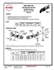
INSTALLATION TOOLS<br />
These tools are not automatically included. Must be specified on order.<br />
AB2000 AITCS AB5000 ABTT<br />
Pulling Block to help pull<br />
conductors in system.<br />
Copper Straightener<br />
to remove bend in<br />
AB125 or higher<br />
copper.<br />
Tom Thumb with<br />
wheels to assist in<br />
installing sealing strip<br />
on long systems.<br />
Tom Thumb without<br />
wheels to assist in<br />
installing sealing strips.<br />
© Aero-Motive<br />
Company<br />
Apr-03
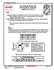
AFC3 AITRC AB600K<br />
Copper Cassette to hold copper<br />
while pulling it in housing.<br />
Copper Holding Turntable for<br />
lengths of copper bigger than the<br />
AFC3 capacity.<br />
Copper End Forming Angle<br />
For making proper “L” shape bend<br />
at splice joints and end feed.<br />
POWER SOURCE CONNECTION<br />
All systems use either Line Feed or End Feed box for connection to power source.<br />
• Line Feed - Installation of feed box at any point along the housing.<br />
• End Feed – Installation at end of system<br />
• Multiple Feeds – Some system lengths require more than one box. Consult factory for proper<br />
installation details.<br />
STEP #1 - MOUNTING<br />
Sliding Hangers and Fixed-Point Clamps support housing.<br />
• Fixed Point Clamp - Rigidly fixes housing to support structure. System expands and contracts from<br />
this point. Install adjacent to power feeding box. Line feed uses one on either side of feed box.<br />
• Sliding Hanger – Allows housing to freely slide from fixed-point clamp as temperature changes.<br />
Install hangers every 5ft. (See diagram below).<br />
Fixed Point<br />
Clamp<br />
AB400K<br />
Sliding<br />
Hanger<br />
AB500K<br />
Joint<br />
Clamp<br />
AB300K<br />
End Feed<br />
Box<br />
ABEB<br />
Line Feed Box & Housing<br />
ABLB-80 or -160<br />
END FEED<br />
LINE FEED<br />
End Cap<br />
AHBEC<br />
Housing x 10 ft.<br />
ABH10<br />
Mounting supports must have slotted holes, or other provision, for horizontal adjustment to properly align<br />
system. If purchased, Universal Support Bracket is adjustable. Make sure supports are long enough for<br />
machinery to clear housing and feed box.<br />
NOTE: Horizontal sliding hanger adjustment must be provided by the mounting support (by customer).<br />
Install all sliding hanger brackets to mounting supports. Do not tighten top two nuts of mounting support<br />
until housings are in brackets. Final alignment adjustments require housings to be in place.<br />
SM6010-06B Page 2 of 13 ©Aero-Motive Company Apr-03
Housing alignment is critical.<br />
Hanger must not be cocked, or otherwise restrict<br />
free movement of housing through hanger.<br />
Sliding hanger comes with long bolt to allow vertical<br />
adjustment. Minimize distance between support and hanger.<br />
STEP #2 – SLIDE IN HOUSINGS<br />
WARNING:<br />
NOTE:<br />
Optional Universal Support Bracket<br />
Proper alignment of system is critical. All housings must butt with each other before taping<br />
and clamping. Housings must follow an a parallel path to trolley tow arm.<br />
Important: systems up to 300 FPM must be within + one inch of trolley tow arm path.<br />
Install first housing. If end feed, housing is 10ft section.<br />
If line feed, single 5 ft. section with slots (clamp type), or two<br />
2.5-ft sections with mating notched ends (splice type).<br />
Install feed box plate(s).<br />
Install fixed point clamp(s). Slide remaining housings into<br />
sliding hangers. All housings must have alignment stripe on<br />
same side. Align brackets as needed. All housings must<br />
meet at joints before installing tape. Failure to do this will<br />
require reinstallation of housings. On splice line feed do not<br />
install joining pins or top plate. Install only after pulling<br />
copper.<br />
Install end collar pieces from line feed box or end feed<br />
box before mounting of housing. These parts are difficult<br />
to install as installation progresses.<br />
STEP #3 – TAPE AND CLAMP ALL JOINTS<br />
WARNING: AT50 tape must be used on all housing joints to maintain 600V rating.<br />
NOTE:<br />
Joints must be taped with AT50 insulating tape after housings<br />
and feed sections are installed. Apply tape around entire<br />
housing, then cut opening for bottom slot. Tape must around<br />
bottom lip of housing Both Indoor and outdoor installations<br />
required this tape.<br />
Before installing joint clamp, make sure tape goes around<br />
lower housing lip to sealing strip slot.<br />
SM6010-06B Page 3 of 13 ©Aero-Motive Company Apr-03
NOTE: Some systems require expansion joints to absorb housing expansion if movement is restricted or<br />
excessive. Tape and joint clamp are not used at some or all joints.<br />
See Special Components section: Expansion Joints.<br />
NOTE:<br />
Place joint clamp halves under lip of housing and squeeze<br />
together top fins, install and tighten screws. Repeat for all<br />
housings. Check that joint clamp does not compress or<br />
spread housing’s opening. Opening “A” at bottom of<br />
housing should be about .39-.59 in. for trolley to freely<br />
pass. To fix, either squeeze clamps together, or twist a<br />
small flat piece of wood in housing to adjust gap.<br />
Before installing conductors check inner trolley path.<br />
Insert trolley in housing and pull by hand through<br />
entire system, checking for restrictions to travel.<br />
This checks for alignment stripes on wrong side, housings<br />
with damaged internals, and locations where bottom slot<br />
constricts trolley travel.<br />
STEP #4 – PULL COPPER CONDUCTORS<br />
NOTE:<br />
CONDUCTOR INSTALLATION<br />
First identify proper conductor<br />
locations based total number.<br />
Trolley can enter housing<br />
only one way. Check that<br />
appropriate brushes will<br />
match your intended<br />
conductor locations.<br />
CAUTION: Conductors in any other configuration will cause premature trolley wear.<br />
NOTE:<br />
Use copper cassette/turntable to<br />
hold conductor when pulling<br />
copper. Proper support of<br />
cassette is required; otherwise<br />
damage to conductor is possible<br />
during installation.<br />
Attach pulling block connector to<br />
conductor<br />
Check minimum towing angle of<br />
pulling block below.<br />
SM6010-06B Page 4 of 13 ©Aero-Motive Company Apr-03
NOTE: Thicker AB125 and AB160 conductors require a copper straightener.<br />
Thread copper end though straightener before attaching pulling block.<br />
Straightener takes bend out of thick copper and assures easy pulling.<br />
NOTE:<br />
NOTE:<br />
End Feed<br />
All feed box plates must be installed prior to conductor<br />
installation. Pull conductors from end feed box end.<br />
Copper bend at center of coil must face out at feed<br />
box end. Carefully choose which side to lay copper in<br />
cassette. See pulling diagram below.<br />
Line Feed – Clamp (Slotted Housing)<br />
Most Line feed systems use a 5-ft. line<br />
feed housing with slots and conductor<br />
clamps. Conductors may be pulled from<br />
either end of system. Position of copper<br />
bend is not critical since ends are cut off<br />
before installing end caps.<br />
Line Feed clamps at the feed box must be<br />
in position before pulling copper. They<br />
cannot be installed after copper is<br />
installed. Check to make sure copper<br />
slides through this clamp, and retains<br />
clamp before pulling copper to end.<br />
125a copper has longer clamp plates.<br />
They must be installed with bus bar<br />
facing out to maintain 600v rating. No<br />
overlapping allowed.<br />
SM6010-06B Page 5 of 13 ©Aero-Motive Company Apr-03
NOTE:<br />
Line Feed – Splice<br />
Some line feed systems use a splice connection. A splice housing is two short 2.5 ft. sections with<br />
mating notched ends. Push sealing slot alignment pins completely into one housing. (After all copper is<br />
pulled and housings aligned, these pins are slid half into adjacent housing.)<br />
Remove one fixed-point clamp and pull housing to side so you can pull conductors like end feed.<br />
Copper bend at center of coil must face<br />
out at line feed box. Carefully choose which<br />
side to lay copper in cassette. See pulling<br />
diagram on previous page.<br />
The AB600K copper bending angle can be<br />
used to quickly make copper bend for splice<br />
feeds. Example: For AB125 use 125 hole.<br />
File down wedges as required by copper<br />
thickness and install at joint, behind<br />
conductor, to align inside facing edges.<br />
After all conductors are installed in both<br />
directions, realign housing, attach fixed-point<br />
clamp, and tap alignment pins into place,<br />
install top bracket, and bolt conductors<br />
together.<br />
If using sealing strips, alignment pins do not<br />
allow engagement of strip. Trim back strip<br />
engagement edge (about 2 in.), and continue<br />
installing.<br />
SM6010-06B Page 6 of 13 ©Aero-Motive Company Apr-03
STEP #5 – MAKE REQUIRED CABLE CONNECTIONS<br />
WARNING:<br />
Fuse size must not be greater than maximum amperage capacity of system.<br />
Hazards or unsafe practices COULD result in severe personal injury or death.<br />
CONNECTING POWER SUPPLY<br />
Connect proper power supply cable<br />
though end plate to conductor<br />
connection bolts. Drill hole in end plate<br />
as needed for conduit connection.<br />
DO NOT OVER TIGHTEN bolts on line<br />
feed clamps. Connection screw may<br />
damage conductor and impact brush<br />
wear.<br />
The plate for end feed box is shown. If<br />
Line feed supply power connects<br />
directly to clamps or conductor splice.<br />
SEALING STRIPS (accessory)<br />
This item is supplied in a dual molded strip with both<br />
sides ready to install simultaneously. A thin web holds<br />
them together and is easily separated during<br />
installation. If splicing of strip is needed, use a<br />
Cyanoacrylate (Super/Krazy glue) to fix strip to housing<br />
at that point. Trim back lip at an angle so trolley does<br />
not catch strip edge.<br />
If strips are dry it is necessary to use a lubricant to aid in<br />
their installation Wipe mineral oil, or diluted siliconewater<br />
solution (20% silicone oil /80% water) on strip<br />
while installing.<br />
Two methods of installation.<br />
HAND (short systems): Begin with end of sealing strip,<br />
insert into housing slot as shown. Engage rest of strip<br />
into slot with fingers. Leave extra on end for end cap(s).<br />
TOM THUMB – AB5000 and ABTT: Feed sealing strips<br />
through Tom Thumb and start into housing. Pull through<br />
system. Adjust pressing feet as needed on AB5000 only.<br />
STEP #6 – INSTALL TROLLEY AND TOW ARM<br />
INSTALLING TROLLEYS AND TOW ARMS<br />
Insert trolley into an open end of system, taking<br />
notice of small polarizing pilot guide on trolley.<br />
Trolleys can be inserted in only one direction<br />
according to anti-reverse slot. Carefully push in<br />
each brush until entire trolley is inside. Hand pull<br />
trolley through housing to make sure conductors<br />
are correctly installed, and joints at a line feed<br />
splice are smooth. If trolley catches on conductor<br />
joint, rework until transition is smooth.<br />
ABSS<br />
AB5000<br />
SM6010-06B Page 7 of 13 ©Aero-Motive Company Apr-03<br />
ABTT
To prolong brush life, and resist serious<br />
trolley wear, trolley must run in-line and<br />
without undue resistance throughout<br />
housing.<br />
• Cable loop must be generous, without<br />
any side pulling of trolley.<br />
• Tow arm chain connection point must be<br />
3/8 to1-1/8 in. lower than trolley<br />
connection.<br />
• When pulling, the chain on the other side<br />
must have a little sag. See picture.<br />
• Tow arm tow chains must be adjusted for<br />
minimum side pulling of trolley.<br />
STEP #7 – INSTALL FEED BOX COVERS AND END CAP(S)<br />
INSTALLING END OR LINE FEED<br />
COVERS<br />
END FEED SYSTEMS – The Clamp plate is<br />
required to secure end feed collar to<br />
housing. Insert clamp plate assembly and<br />
push up against feed box plate before<br />
tightening. With gasket in place, fasten box<br />
cover to end plate collar.<br />
LINE FEED SYSTEMS – Insert gaskets in<br />
line feed box collar plates. Place line feed<br />
box cover between the two plates. Thread<br />
nut on one end of each threaded rod. Insert<br />
rods (with cap nut attached) into end<br />
sections, through cover and into opposite<br />
end collar plate. Align cover and securely<br />
tighten hardware.<br />
INSTALL END CAPS<br />
Trim all protruding conductors to 2 inches<br />
from housing end. Slide end cap over<br />
conductors and into each adjacent slot. Hold<br />
to housing and install insulating tape around<br />
joint to sealing strip slot.<br />
Install joint clamp and tighten all hardware.<br />
STEP #7 – FINAL CHECK<br />
Check These Items<br />
• Trolley is pulled in-line with system and cable pigtail is not affecting trolley posture.<br />
• Housings are aligned within required tolerance specified in step two.<br />
• No interference between feed boxes and equipment<br />
• Hard ware on all sliding hangers, fixed point clamps, and feed boxes is tightened.<br />
• Sliding hangers allow housing to freely slide as temperature changes.<br />
• Sealing strip, if installed, is engaged with slot along total length.<br />
• No squeezing or spreading of housings at joints or hangers.<br />
SM6010-06B Page 8 of 13 ©Aero-Motive Company Apr-03
SPECIAL SYSTEM COMPONENTS<br />
TRANSFER TRUMPET HOUSINGS (ABHT)<br />
NOTE: <strong>AeroBar</strong> transfer trumpets assemblies are made without the anti-reverse rib (no housing stripe)<br />
and can be installed on either end of system. Make sure trolley is installed properly to match main<br />
housing stripe.<br />
Trumpet Housing<br />
Trumpet transfers are mounted with a<br />
fixed point on either side of a line feed<br />
box. Trumpet end half of housing comes<br />
with 125amp copper installed.<br />
The other housing is attached to rest of<br />
system. Conductor joint is handled like<br />
a splice line feed (page 6).<br />
At splice joint conductors must be<br />
aligned for smoothest possible brush<br />
transition. Check with trolley.<br />
There is no stripe on the transfer<br />
housing so it is unpolarized and can be<br />
used at any transfer.<br />
Alignment<br />
ABHT trumpet transfers require horizontal and vertical alignment to be<br />
within .394”. Distance between trumpets can vary.<br />
Trolleys and Tow Arms<br />
Trumpet transfers require a spring loaded tow arm (ABTP) or a trolley tow bar pulled by chains.<br />
Multiple trolleys are commonly needed to maintain power during transfer.<br />
SM6010-06B Page 9 of 13 ©Aero-Motive Company Apr-03
Spring Loaded Tow Arm<br />
Must be separated by “X”<br />
distance to maintain<br />
brush contact on at least<br />
one or more trolleys<br />
during transfer.<br />
Tow bar Trolley<br />
(Special)<br />
Alternative to spring<br />
loaded tow arm is long<br />
bar pulled by chains.<br />
EXPANSION JOINTS (ABEJ)<br />
Expansion joints are used when housings are locked-in and unable to freely expand. Also are used if<br />
length of system and ambient change exceeds allowable limits.<br />
Rule #1: Any housing section with expansion joint must have a corresponding fixed-point clamp.<br />
Each fixed-point clamp replaces one sliding hanger, and section expands and contracts from this fixedpoint<br />
clamp into the expansion joint. A fixed-point clamp is included with each ABEJ.<br />
Rule #2: The ambient temperature range determines how many expansion joints are needed<br />
STEP #1 – Identify Type System<br />
Type #1 – End feed and Transfer on Opposite Ends.<br />
Expansion joints are needed on housing joints between the two feed boxes.<br />
Type #2 – Two Feed Boxes.<br />
Expansion joints are needed on housing joints between the two feed boxes.<br />
Type #3 – Long <strong>Systems</strong><br />
Expansion joints are needed on part of system to reduce expansion to an acceptable range.<br />
Type #1 and #2 require copper to be bent and drilled to mate with adjoining copper end. Copper splice joint<br />
must be smooth. Use conductor wedges behind copper to assist in this process. Check splice with trolley<br />
before putting system into operation. (See page 6)<br />
SM6010-06B Page 10 of 13 ©Aero-Motive Company Apr-03
WARNING:<br />
STEP #2 –Setting the Gap.<br />
Proper gap at expansion joint is critical. Too much and trolley may not work properly.<br />
Too little and housing may deflect at high-end temperatures causing system damage.<br />
Make sure to properly insert the housing into expansion joint. Before installing<br />
adjacent fixed-point clamp, the gap at expansion joint must be set. Gaps are<br />
calculated based on the chart below. Maximum expected temperature and<br />
temperature at time of mounting determine the answer.<br />
A petroleum lubricant on sealing web inside the expansion joint may aid in installation.<br />
Set Gap according to chart intersection of<br />
maximum ambient (horizontal) and mounting temperature (diagonal).<br />
This chart is for use<br />
with expansion joints<br />
at every housing joint,<br />
every 10ft.<br />
If installing at 20 ft.<br />
(every other joint),<br />
then double Set Gap<br />
distance.<br />
Note: Maximum total<br />
gap not to exceed 1”.<br />
Example<br />
ABEJ every: 10ft<br />
Max Ambient: 104 F<br />
Mounting Temp: 50 F<br />
Then Set Gap: .27”<br />
or,<br />
If ABEJ every: 20ft<br />
Then Set Gap: .52”<br />
STEP #3 – Special Trolley<br />
Single gang ABT trolley is not<br />
allowed on expansion systems.<br />
Must use a double or triple<br />
ganged trolley.<br />
SM6010-06B Page 11 of 13 ©Aero-Motive Company Apr-03
INSPECTION UNIT (ABIU)<br />
WARNING AT50 tape must be used on all housing joints to maintain 600V rating.<br />
Inspection unit mounts at joint of two ABH<br />
housings. ABIU length is 8”: and is long<br />
enough to remove a single gang.<br />
If long system, the extra length of the ABIU<br />
might shift successive joint clamps too<br />
close to adjacent sliding hangers.<br />
If so, cut 8” from one ABH so overall<br />
housing length is not affected.<br />
Note: The inspection unit is not required to<br />
for inspection of trolley unless you have<br />
a closed loop system.<br />
Otherwise remove trolley from an end<br />
cap or end feed box end.<br />
ADJUSTMENT<br />
TROLLEY ALIGNMENT<br />
Critical to proper system operation is alignment of housing and trolley tow arm.<br />
If unusual wear is found on trolley, housings and towing may need adjustment.<br />
INSPECTION<br />
WARNING:<br />
Always disconnect electrical power before dismantling any part of system. Fuse size must<br />
not be greater than maximum amperage capacity of system.<br />
Hazards or unsafe practices COULD result in severe personal injury or death.<br />
TROLLEY<br />
• Check brush for any unusual wear grooves.<br />
• Check brush wear-line to edge of worn brush.<br />
• Check wheels for tight bearings and wear.<br />
• Check trolley neck, and body, for wear.<br />
• Check pigtail cable for side pulling.<br />
TOW ARM<br />
• Check tow chains and shackles for wear.<br />
• Check tow chain slack. Cannot be too tight. Chains<br />
must be long enough to allow for some side to side<br />
movement.<br />
• Check tow arm mounting and alignment with track.<br />
HOUSING<br />
• Check housing joints for secure grip between<br />
adjoining housing.<br />
• Check sliding hangers for free movement of housing.<br />
Tilted or cocked hangers must be aligned and<br />
tightened (see diagram).<br />
• Check housing bottom slot for consistent opening.<br />
Pinching by joint clamps or sliding hangers must be<br />
corrected to .39-.59 in. width.<br />
• Check support arms for stability. Must be horizontal<br />
and rigid.<br />
SM6010-06B Page 12 of 13 ©Aero-Motive Company Apr-03
SEALING STRIP<br />
• Check strip engagement over entire length.<br />
• Check condition for open seams, and wear.<br />
• Check trolley-neck wear caused by sealing strip.<br />
COPPER CONDUCTORS<br />
• Check for smooth surface. Uneven pulling force of<br />
trolley may indicate pitting. Gently spread housing and<br />
visually inspect conductors.<br />
MAINTENANCE<br />
TROLLEY<br />
Trolley brushes require changing as they<br />
approach brush wear line. Replace brush by<br />
removing retaining screw. Insert new brush,<br />
being very careful to place replacement<br />
brush over retaining spring and shunt wires<br />
into groves. Reinsert retaining screw and<br />
tighten. Push brush back and forth to check<br />
for free movement.<br />
REPLACEMENT PARTS<br />
Ref<br />
No.<br />
A<br />
SM6010-06B<br />
Part<br />
Number<br />
H44600051 2<br />
H44600041 2<br />
Qty. Description<br />
B N7K91P 3-5 Trolley brush<br />
C R62400002 5.5’ 5c Cable<br />
D H11610006 2 Tow Chain<br />
Not<br />
Shown<br />
Load Wheel Kit No Bearing (2<br />
wheels, 1 shaft , 1 retainer)<br />
Load Wheel Kit Ball Bearing<br />
(2 wheels, 1 shaft , 1 retainer)<br />
C75540112 AR Right Angle Connector<br />
H44600001 2<br />
H44600011 2<br />
Snap on Top Wheel<br />
Assembly No Bearing<br />
Snap on Top Wheel<br />
Assembly Ball Bearing<br />
H44600021 2 Snap on Top Wheel w/ Side Roller No Bearing.<br />
H44600031 2 Snap on Top Wheel w/ Side Roller Ball Bearing.<br />
H18110026 AR Trolley Connector Kit (tow plate and dovetail connection parts.<br />
www.woodhead.com<br />
Page<br />
1 3 o f 1 3<br />
© Aero-Motive<br />
Company<br />
Apr-03