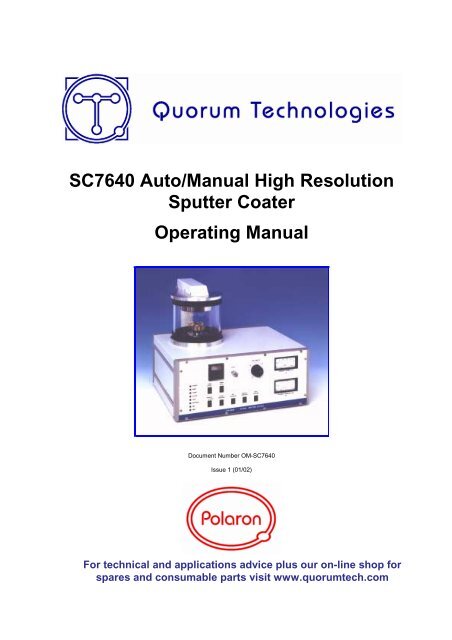
SC7640 Auto/Manual High Resolution Sputter Coater Operating ...
SC7640 Auto/Manual High Resolution Sputter Coater Operating ...
SC7640 Auto/Manual High Resolution Sputter Coater Operating ...

Create successful ePaper yourself
Turn your PDF publications into a flip-book with our unique Google optimized e-Paper software.
<strong>SC7640</strong> <strong>Auto</strong>/<strong>Manual</strong> <strong>High</strong> <strong>Resolution</strong><br />
<strong>Sputter</strong> <strong>Coater</strong><br />
<strong>Operating</strong> <strong>Manual</strong><br />
Document Number OM-<strong>SC7640</strong><br />
Issue 1 (01/02)<br />
For technical and applications advice plus our on-line shop for<br />
spares and consumable parts visit www.quorumtech.com
Quorum Technologies Ltd is the owner and manufacture of the<br />
preparation equipment.<br />
Unit 15A<br />
Euro Business Park<br />
New Road<br />
Newhaven<br />
East Sussex<br />
range of EM<br />
U.K. tel: ++44(0) 1273 510535<br />
BN9 0DQ fax: ++44(0) 1273 510536<br />
Email : sales@quorumtech.com<br />
http:///www.quorumtech.com<br />
For further information regarding any of the other products designed and manufactured by Quorum<br />
Technologies, contact your local representative or directly to Quorum Technologies at the address<br />
above.<br />
• Carbon and <strong>Sputter</strong> <strong>Coater</strong>s<br />
• Plasma Reactor for ashing and etching<br />
• <strong>High</strong> Vacuum Bench Top Evaporators<br />
• Cryo Transfer Systems<br />
• Critical Point Dryers<br />
• Service and Spares<br />
For technical and applications advice plus our on-line shop for spares and<br />
consumable parts visit www.quorumtech.com<br />
Disclaimer<br />
The components and packages described in this document are mutually compatible and<br />
guaranteed to meet or exceed the published performance specifications. No performance<br />
guarantees, however, can be given in circumstances where these component packages are used in<br />
conjunction with equipment supplied by companies other than Quorum Technologies.<br />
Quorum Technologies Ltd. Company No. 4273003. Registered offices 30/34 North Street Hailsham, East Sussex, England, BN27 1DW
OM-<strong>SC7640</strong> Contents<br />
1 Contents<br />
1.1 <strong>Manual</strong> Layout<br />
This <strong>Operating</strong> <strong>Manual</strong> is divided up into the following major section, each chapter dealing with<br />
specific topics, as follows:<br />
Chapter 1 - Contents<br />
Chapter 2 - Health and Safety<br />
General section which applies to all Quorum Technologies Polaron products detailing the<br />
very important issues of Health and Safety applicable when using sample preparation<br />
equipment.<br />
Chapter 3 - Introduction<br />
Introduces this manual.<br />
Chapter 4 - General Description<br />
Identifies each of the equipment items and provides an overview of their functions and<br />
how they work.<br />
Chapter 5 - Installation<br />
Instructions on how this Instrument should be installed and the connections which should<br />
be made between the equipment items.<br />
Chapter 6 - Operation<br />
Instructions on how to start-up and run the instrument.<br />
Chapter 7 - Maintenance<br />
Instructions on how to check the system is functioning correctly, and how to change<br />
consumable items. Details of appropriate spare parts.<br />
Chapter 8 - Fault Finding<br />
Information on how to identify faults in the system and how to rectify these faults.<br />
Chapter 9 - Agents<br />
List of main agents supporting the Quorum Technologies product range.<br />
Chapter 10 - Index<br />
Issue 1 3 <strong>SC7640</strong> <strong>Sputter</strong> <strong>Coater</strong>
Contents OM-<strong>SC7640</strong><br />
1.2 Chapter Contents<br />
Chapter 1 - Contents ................................................................................................ 3<br />
1.1 <strong>Manual</strong> Layout ................................................................................ 3<br />
1.2 Chapter Contents ........................................................................... 4<br />
1.3 Illustrations ..................................................................................... 6<br />
1.4 Tables ............................................................................................ 6<br />
Chapter 2 - Health and Safety ................................................................................. 7<br />
2.1 Control of Substances Hazardous to Health (COSHH) ................. 7<br />
2.2 Safety Policy ................................................................................... 7<br />
2.3 Conformity ...................................................................................... 7<br />
2.4 Servicing ........................................................................................ 8<br />
2.4.1 Disclaimer ............................................................................... 8<br />
2.4.2 Operators and Service Engineers .......................................... 8<br />
2.5 Hazard Signals and Signs .............................................................. 8<br />
2.5.1 Hazard Signal Words ............................................................. 8<br />
2.5.2 Hazard Labels used on Equipment ........................................ 8<br />
2.5.3 Hazard Warning Labels used in Equipment <strong>Manual</strong>s ............ 9<br />
2.5.4 Instrument Functionality Signs ............................................... 9<br />
2.5.5 Serious Damage to Instruments ............................................. 9<br />
2.5.6 Hazard to Operator ................................................................. 9<br />
2.6 Risk Analysis .................................................................................. 10<br />
2.6.1 Personal Operational Risks .................................................... 10<br />
2.6.2 Hazardous Materials ............................................................... 10<br />
2.7 Good Working Practices ................................................................ 11<br />
2.8 <strong>SC7640</strong> <strong>Sputter</strong> <strong>Coater</strong> Specific Safety Hazards ........................... 11<br />
2.8.1 Contamination ........................................................................ 11<br />
Chapter 3 - Introduction............................................................................................ 12<br />
3.1 Return of Goods ............................................................................. 12<br />
3.2 Returns Procedure ......................................................................... 12<br />
Chapter 4 - Description ............................................................................................ 13<br />
4.1 Equipment ...................................................................................... 13<br />
4.1.1 Accessories ............................................................................ 13<br />
4.1.2 Optional Items ........................................................................ 13<br />
4.1.3 Optional Accessories .............................................................. 14<br />
4.2 Overview ........................................................................................ 15<br />
4.3 Technical Specification .................................................................. 15<br />
4.3.1 <strong>SC7640</strong> <strong>Sputter</strong> <strong>Coater</strong> Specification ..................................... 15<br />
4.4 Physical Description ....................................................................... 16<br />
4.4.1 Operational Description .......................................................... 17<br />
4.4.2 Pumping Requirements .......................................................... 17<br />
4.5 Interlocks ........................................................................................ 17<br />
4.6 <strong>SC7640</strong> Panel Details .................................................................... 18<br />
4.6.1 <strong>SC7640</strong>, Front Panel Controls ................................................ 18<br />
4.6.2 <strong>SC7640</strong>, Rear Panel Connections .......................................... 19<br />
Chapter 5 - Installation ............................................................................................. 20<br />
5.1 Unpacking Checklist ...................................................................... 20<br />
5.1.1 Preparation ............................................................................. 20<br />
5.2 <strong>SC7640</strong> Installation ........................................................................ 21<br />
5.2.1 Connections ............................................................................ 21<br />
5.3 Installation of Optional Accessories ............................................... 22<br />
5.3.1 FT7607 Crystal Holder Stage ................................................. 23<br />
5.3.2 RC7606 Rotary Planetary Stage ............................................ 23<br />
5.3.3 WS7608 Water Cooled Stage................................................. 23<br />
<strong>SC7640</strong> <strong>Sputter</strong> <strong>Coater</strong> 4 Issue 1
OM-<strong>SC7640</strong> Contents<br />
Chapter 6 - Operation .............................................................................................. 24<br />
6.1 Test Procedure ............................................................................... 24<br />
6.2 Coating Process ............................................................................. 26<br />
6.3 Coating Specimens ........................................................................ 26<br />
6.3.1 Coating in <strong>Manual</strong> Mode - <strong>High</strong> <strong>Resolution</strong> ............................ 26<br />
6.3.2 Coating in <strong>Manual</strong> Mode - Routine ......................................... 28<br />
6.3.3 Coating in <strong>Auto</strong>matic Mode .................................................... 29<br />
6.4 <strong>Sputter</strong>ing Rates ............................................................................ 30<br />
Chapter 7 - Maintenance .......................................................................................... 31<br />
7.1 Maintenance - General .................................................................. 31<br />
7.2 Cleaning ......................................................................................... 31<br />
7.2.1 Vacuum Chamber Cleaning ................................................... 31<br />
7.3 Target Replacement ...................................................................... 32<br />
7.3.1 Target Removal ...................................................................... 32<br />
7.3.2 Refit New Target .................................................................... 32<br />
7.4 No Plasma Current ........................................................................ 33<br />
7.5 Spare Parts ..................................................................................... 33<br />
Chapter 8 - Fault Finding ......................................................................................... 34<br />
8.1 Trouble Shooting / Fault Finding .................................................... 34<br />
8.2 Fault Prevention ............................................................................. 34<br />
Chapter 9 - Agents ................................................................................................... 35<br />
Chapter 10 - Index .................................................................................................... 36<br />
Issue 1 5 <strong>SC7640</strong> <strong>Sputter</strong> <strong>Coater</strong>
Contents OM-<strong>SC7640</strong><br />
1.3 Illustrations<br />
1.4 Tables<br />
Figure 2.1 - Hazard Warning Symbols ....................................................................... 8<br />
Figure 2.2 - International Warning Symbols ............................................................... 9<br />
Figure 2.3 - Typical Signs as shown in this <strong>Manual</strong> .................................................... 9<br />
Figure 2.4 - Typical Signs as shown in this <strong>Manual</strong> ................................................... 9<br />
Figure 2.5 - Typical Warnings, as shown in this <strong>Manual</strong> ............................................ 9<br />
Figure 4.1 - <strong>SC7640</strong> <strong>Sputter</strong> <strong>Coater</strong> ........................................................................... 16<br />
Figure 4.2 - <strong>SC7640</strong> <strong>Sputter</strong> <strong>Coater</strong> Operation........................................................... 17<br />
Figure 4.3 - <strong>SC7640</strong> <strong>Sputter</strong> <strong>Coater</strong>, Front Panel Controls ........................................ 18<br />
Figure 4.4 - <strong>SC7640</strong> <strong>Sputter</strong> <strong>Coater</strong>, Rear Panel Connections .................................. 19<br />
Figure 5.1 - <strong>SC7640</strong> Connections .............................................................................. 22<br />
Figure 6.1 - <strong>Sputter</strong>ing Rates ..................................................................................... 30<br />
Figure 7.1 - Target Replacement ............................................................................... 32<br />
Table 2.1 - Personal Operational Risks ...................................................................... 10<br />
Table 4.1 - <strong>SC7640</strong> <strong>Sputter</strong> <strong>Coater</strong>, Front Panel Control Descriptions ...................... 18<br />
Table 4.2 - <strong>SC7640</strong> <strong>Sputter</strong> <strong>Coater</strong>, Rear Panel Connection Descriptions ................ 19<br />
Table 7.1 - Spare Parts .............................................................................................. 33<br />
Table 8.1 - Trouble Shooting ...................................................................................... 34<br />
Table 8.2 - Fault Prevention ....................................................................................... 34<br />
Table 9.1 - List of Agents Supporting Quorum Technologies Products ..................... 35<br />
<strong>SC7640</strong> <strong>Sputter</strong> <strong>Coater</strong> 6 Issue 1
OM-<strong>SC7640</strong> Health and Safety<br />
2 Health and Safety<br />
Safety is very important when using any instrumentation and this chapter should be read by all<br />
users of our equipment.<br />
This section of the <strong>Manual</strong> applies to all surface analysis and surface preparation equipment<br />
supplied by Quorum Technologies Polaron range of products, not just the particular instrument for<br />
which the manual refers.<br />
Included in this chapter are details on warning notations, good working practices and information on<br />
European Community (EC) legislation regarding “Control Of Substances Hazardous to Health”<br />
(COSHH) and risk analysis.<br />
2.1 Control of Substances Hazardous to Health (COSHH)<br />
The E.C. legislation regarding the “Control of Substances Hazardous to Health” requires Quorum<br />
Technologies to monitor and assess every substance entering or leaving their premises.<br />
Consequently any returned goods of whatever nature must be accompanied by a declaration form<br />
available from Quorum Technologies, reference number SP-100. Without this declaration Quorum<br />
Technologies reserves the right not to handle the substance/item. Also in accordance with E.C.<br />
regulations we will supply on request hazard data sheets for substances used in our instruments.<br />
2.2 Safety Policy<br />
This section contains important information relating to all health and safety aspects of the<br />
equipment. As such it should be read, and understood, by all personnel using the instrument<br />
whether as an operator or in a service capacity.<br />
Quorum Technologies is committed to providing a safe working environment for its employees and<br />
those that use it's equipment and conducts its business responsibly, and in a manner designed to<br />
protect the health and safety of its customers, employees and the public at large. It also seeks to<br />
minimise any adverse effects that its activities may have on the environment.<br />
Quorum Technologies regularly reviews its operations to make environmental, health and safety<br />
improvements in line with UK and European Community legislation.<br />
The equipment has been designed as free-standing bench mounted instruments. Quorum<br />
Technologies cannot be held responsible for any damage, injury or consequential loss arising from<br />
the use of its equipment for any other purposes, or any unauthorised modifications made to the<br />
equipment.<br />
All service work carried out on the equipment should only be undertaken by suitably qualified<br />
personnel. Quorum Technologies is not liable for any damage, injury or consequential loss resulting<br />
from servicing by unqualified personnel. Quorum Technologies will also not be liable for damage,<br />
injury or consequential loss resulting from incorrect operation of the instrument or modification of<br />
the instrument.<br />
2.3 Conformity<br />
This instrument is supplied in a form that complies with the protection requirements of the EC<br />
Electromagnetic Compatibility Directive 89/336/EEC and the essential health and safety<br />
requirements of the low voltage directive 72/23/EEC both as amended by 92/31/EEC. Any<br />
modifications to the equipment, including electronics or cable layout may affect the compliance with<br />
these directives.<br />
Issue 1 7 <strong>SC7640</strong> <strong>Sputter</strong> <strong>Coater</strong>
Health and Safety OM-<strong>SC7640</strong><br />
2.4 Servicing<br />
2.4.1 Disclaimer<br />
All service work on the equipment should be carried out by qualified personnel. Quorum<br />
Technologies cannot be liable for damage, injury or consequential loss resulting from servicing from<br />
unqualified personnel. Quorum Technologies will also not be liable for damage, injury or<br />
consequential loss resulting from incorrect operation of the instrument or modification of the<br />
instrument.<br />
2.4.2 Operators and Service Engineers<br />
A normal operator of the equipment will not be trained in or qualified for service work on the<br />
equipment and may cause a hazard to himself/herself or others if such work is attempted.<br />
Operators should therefore restrict themselves to the normal operation of the equipment and not by<br />
removing covers from the electronic equipment or dismantling of the instruments.<br />
Service Engineers who are suitably trained to assess and isolate electrical, mechanical and vacuum<br />
hazards should be the only personnel who access the equipment.<br />
2.5 Hazard Signals and Signs<br />
2.5.1 Hazard Signal Words<br />
The standard three hazard signal words are defined as follows:<br />
◆ DANGER - imminently hazardous situation or unsafe practice that, if not avoided, will<br />
result in death or severe injury.<br />
◆ WARNING - potentially hazardous situation or unsafe practice that, if not avoided, could<br />
result in death or severe injury.<br />
◆ CAUTION - potentially hazardous situation or unsafe practice that, if not avoided, may<br />
result in minor or moderate injury or damage to equipment.<br />
2.5.2 Hazard Labels used on Equipment<br />
Several hazard symbols may be found on the equipment, they are shown below with their meaning:<br />
Caution, risk of electric shock<br />
Easily touched higher temperature<br />
parts<br />
Caution (refer to accompanying documents)<br />
Figure 2.1 - Hazard Warning Symbols<br />
Warning, risk of electric shock<br />
<strong>SC7640</strong> <strong>Sputter</strong> <strong>Coater</strong> 8 Issue 1
OM-<strong>SC7640</strong> Health and Safety<br />
2.5.3 Hazard Warning Labels used in Equipment <strong>Manual</strong>s<br />
The international warning signs used in equipment manuals as shown in Figure 2.2.<br />
Figure 2.2 - International Warning Symbols<br />
Where appropriate these are used when a specific identifiable risk is involved in either using or<br />
maintaining the instrument. These take the form of warning triangles or signs with a graphical<br />
description of the hazard.<br />
2.5.4 Instrument Functionality Signs<br />
CAUTION<br />
Do NOT depress button “P” as this will change the program<br />
Figure 2.3 - Typical Warning sign as shown in this <strong>Manual</strong><br />
This typical sign applies to cautions where there is a risk to the functionality of equipment due to<br />
incorrect operation. These cautions or warnings will be contained in a box and be accompanied by<br />
a circular warning symbol as shown in Figure 2.3.<br />
2.5.5 Serious Damage to Instruments<br />
WARNING<br />
Do NOT operate without first filling the reservoir with water as<br />
this will damage both the pump and the heater.<br />
Figure 2.4 - Typical Warning sign as shown in this <strong>Manual</strong><br />
This typical caution sign is used where serious damage will be caused by incorrect operation of<br />
instrumentation. They will follow the same form as functionality warnings but with a triangular<br />
warning symbol as shown in Figure 2.4.<br />
2.5.6 Hazard to Operator<br />
WARNING<br />
HAZARD TO HEALTH!<br />
Potentially lethal voltages are used in this equipment.<br />
Before making / breaking connections to the equipment, ensure power<br />
is off and that it is safe to proceed.<br />
Figure 2.5 - Typical Warning as shown in this <strong>Manual</strong><br />
These warnings will generally occur in relevant installation and maintaining sections where there<br />
exists a potential hazard to the engineer working on the instrument. They will take the form of the<br />
triangular warning symbol accompanied by an international warning sign and bold type lettering<br />
beginning with “WARNING-HAZARD TO HEALTH!” as shown in Figure 2.5.<br />
Issue 1 9 <strong>SC7640</strong> <strong>Sputter</strong> <strong>Coater</strong>
Health and Safety OM-<strong>SC7640</strong><br />
2.6 Risk Analysis<br />
2.6.1 Personal Operational Risks<br />
The following is a list of tasks carried out by both the operator and service engineer where<br />
recognised risks have been observed, listed is the personnel protection equipment (PPE) which is<br />
suggested for use for various tasks on any surface analysis equipment and systems:<br />
Task Carried out by Nature of Hazard Recommended PPE<br />
Cleaning of parts /<br />
samples with<br />
isopropanol (IPA)<br />
Use of Liquid<br />
Nitrogen in sample<br />
cooling etc.<br />
Operator / Service<br />
engineer<br />
Operator / Service<br />
engineer<br />
Splash hazard to<br />
eyes, drying of skin<br />
Protective goggles,<br />
protective gloves.<br />
Burn risk Thermally protective gloves<br />
and goggles should be worn.<br />
Lifting of Heavy Items Service engineer Dropping on foot. Protective footware.<br />
2.6.2 Hazardous Materials<br />
Table 2.1 - Personal Operational Risks<br />
◆ Isopropanol (IPA)<br />
For certain service tasks isopropanol is suggested for cleaning components before use in the<br />
vacuum system. It should be noted that isopropanol is a flammable liquid and as such should<br />
not be used on hot surfaces. In addition it is recommended that protective gloves are worn<br />
when using isopropanol.<br />
◆ Compressed Air<br />
Compressed air can be a potential hazard if handled inappropriately. A compressed air line<br />
may be fed from some instruments to the customers supply, and the customer should ensure<br />
that this and any other service pipes and cables are maintained in good condition.<br />
◆ Nitrogen, Argon and Helium Gas Supplies<br />
Instruments may use nitrogen, argon or helium gas supplies for their operation, the customer<br />
is responsible for maintaining the supply to the instrument. This supply should be regulated<br />
and kept to the lowest pressure and flow rate as is practical to minimise the effects of any<br />
leaks.<br />
◆ Hazardous Gases<br />
Quorum Technologies has no control over the gases used within the system. It is therefore<br />
viewed as the customers responsibility to assess the hazards involved and take appropriate<br />
precautions when using explosive, toxic or corrosive gases or gases which may result in<br />
hazardous products as a result of a chemical reaction.<br />
<strong>SC7640</strong> <strong>Sputter</strong> <strong>Coater</strong> 10 Issue 1
OM-<strong>SC7640</strong> Health and Safety<br />
2.7 Good Working Practices<br />
It is essential that good hygienic working practices are adopted at all times especially in an ultra<br />
high vacuum or cleanroom environment and are generally of the “Common sense” type. Some<br />
simple good practice rules are:<br />
◆ If in doubt don't.<br />
◆ If in doubt ask.<br />
◆ When handling solvents wear face mask, gloves, apron and work only in a well ventilated<br />
area.<br />
◆ Mop up any spillages immediately.<br />
◆ When handling or decanting mineral oils wear protective clothing.<br />
◆ Aerosols of mineral oils, such as that produced by gas ballasting, can prove to be hazardous<br />
and an exhaust is recommended.<br />
◆ Before attempting to service electrical apparatus, isolate from the mains.<br />
◆ Treat all unknown substances as hazardous.<br />
◆ Dispose of substances in an appropriate manner.<br />
◆ Use the correct tool for the job.<br />
◆ Keep a straight back and bend from the knees when lifting heavy objects.<br />
◆ Wear protective clothing when using liquid nitrogen.<br />
◆ Affix pressurised gas cylinders firmly to walls or racks. Use the correct regulating valves on<br />
gas cylinders and always transport cylinders using the appropriate specialist trolley.<br />
◆ Obey safety regulations regarding lifts, hoists and machine tools.<br />
◆ Always make sure you understand a procedure well before attempting it for the first time.<br />
2.8 <strong>SC7640</strong> Specific Safety Hazards<br />
The following Safety Hazards are specific to the <strong>SC7640</strong> <strong>Sputter</strong> <strong>Coater</strong>.<br />
2.8.1 Contamination<br />
WARNING<br />
HAZARD TO HEALTH!<br />
The Power Supply used in the Model <strong>SC7640</strong> unit can<br />
operate at up to 3000V D.C<br />
HAZARDOUS VOLTAGE OUTPUTS of up to 3000V. D.C.<br />
Contamination can seriously affect the sputtering process. To reduce the possibility of<br />
contamination by airborne particles, minimise the time the vacuum chamber is open to the<br />
atmosphere.<br />
Issue 1 11 <strong>SC7640</strong> <strong>Sputter</strong> <strong>Coater</strong>
Introduction OM-<strong>SC7640</strong><br />
3 Introduction<br />
This manual is intended for all users of the <strong>SC7640</strong> <strong>Sputter</strong> <strong>Coater</strong> manufactured by Quorum<br />
Technologies from the POLARON range and provides information on the installation, operation and<br />
maintenance of the instrument.<br />
Please note that the servicing and maintenance procedures should only be carried out by qualified<br />
service personnel and it is essential that all users should read the Health and Safety section of this<br />
manual.<br />
3.1 Return of Goods<br />
If goods are to be returned to Quorum Technologies for repair or servicing the customer should contact<br />
their local distributor or the factory direct before shipment. A "Returns Authorisation Number" should be<br />
obtained in advance of any shipment. This number is to be clearly marked on the outside of the<br />
shipment. Complete the returned equipment report form, number SP106 with as much detail as<br />
possible and return with the goods.<br />
All returned goods are to be accompanied by a completed "Returned Goods Health and Safety<br />
Clearance" form SP-100 attached to the outside of the package (to be accessible without opening the<br />
package) and a copy of the forms should be faxed in advance to the factory.<br />
When goods are to be returned under warranty refer to the “Warranty Claim, Repair and Returns<br />
Procedure” form number SP-105<br />
Copies of all these forms can be found in the documentation pack supplied with the instrument or<br />
direct from Quorum Technologies, the details can be found on page two of this document.<br />
3.2 Returns Procedure<br />
Warranty Claim<br />
Electronic and basic servicing capabilities exist at most in-country appointed agents, however all<br />
components are sold with a return to factory warranty (unless otherwise stated) which covers<br />
failure during the first 12 months after delivery. In addition to the statutory 12 months warranty this<br />
model carries an additional four year warranty when registered at the time of purchase, for details<br />
refer to form SP-105 in the Service Pack.<br />
Returns must be sent carriage paid, Quorum Technologies will cover the return carriage costs. This<br />
covers defects which arise as a result of a failure in design or manufacturing. It is a condition of<br />
warranty that equipment must be used in accordance with the manufacturers instructions and not<br />
have been subjected to misuse. This warranty does not cover consumable items such as sputter<br />
coating targets and carbon evaporation material. To make a claim under the terms of this warranty<br />
provision contact the Customer Service Department at your local Quorum Technologies<br />
Representative in the first instance.<br />
Chargeable Repairs<br />
Always contact your in-country Quorum Technologies Representative in the first instance. They will<br />
be pleased to assist you and will be able to provide an estimate of repair costs, many offer local<br />
repair facilities.<br />
For routine repairs where down-time is not critical. The target standard return time at Quorum<br />
Technologies is 20 working days.<br />
Returns<br />
All returns to Quorum Technologies require the following procedure to be followed:<br />
1. Contact the local Quorum Technologies Representative and request a Returns Authorisation<br />
Number.<br />
2. Complete a Returned Goods Health and Safety form and returned equipment fault report form.<br />
3. Attach a copy of the completed form to the outside of the package with the usual shipping<br />
documents.<br />
Packaging and Carriage<br />
All goods shipped to the factory must be sealed inside a clean plastic bag and packed in a suitable<br />
carton. If the original packaging is not available Quorum Technologies should be contacted for<br />
advice. Quorum Technologies will not be responsible for damage resulting from inadequate returns<br />
packaging or contamination of delicate structures by stray particles under any circumstances. All nonwarranty<br />
goods returned to the factory must be sent carriage pre-paid, (Free Domicile). They will be<br />
returned carriage forward (Ex-Works).<br />
<strong>SC7640</strong> <strong>Sputter</strong> <strong>Coater</strong> 12 Issue 1
OM-<strong>SC7640</strong> Description<br />
4 Description<br />
4.1 Equipment<br />
Each <strong>SC7640</strong> <strong>Sputter</strong> <strong>Coater</strong> when supplied as a complete package, includes the basic unit, a Gold<br />
Palladium target, a start up kit and operation manual. Items can be ordered as a full package or<br />
separately against the following numbers:<br />
<strong>SC7640</strong> <strong>Sputter</strong> <strong>Coater</strong> 220-240V complete, consisting of the following:<br />
LA764001D <strong>Sputter</strong> <strong>Coater</strong> 220-240V. With Gold/Palladium target<br />
<strong>SC7640</strong>-STARTUP Start up Kit<br />
OM-<strong>SC7640</strong> Operation <strong>Manual</strong><br />
<strong>SC7640</strong>/110V <strong>Sputter</strong> <strong>Coater</strong> 110-120V complete, consisting of the following:<br />
4.1.1 Accessories<br />
LA764002D <strong>Sputter</strong> <strong>Coater</strong> 110-120V. With Gold/Palladium target<br />
<strong>SC7640</strong>-STARTUP Start up Kit<br />
OM-<strong>SC7640</strong> Operation <strong>Manual</strong><br />
The following accessories are available from Quorum Technologies:<br />
E5005G Rotary Pump, 90 1/m, 110/240 Volt, 50/60Hz, fitted with E5004 rotary pump<br />
exhaust filter.<br />
CA7625 A Carbon Coating Accessory which can be associated with either of the<br />
following sputter coaters manufactured by Quorum Technologies is available:<br />
SC7620 or <strong>SC7640</strong>.<br />
This accessory which makes use of the vacuum pump and vacuum control<br />
facilities of the associated sputter coaters, utilises either carbon fibre or carbon<br />
rods in the evaporation process.<br />
A 110 volt version is available as part number CA7625/110V<br />
CA076R Carbon Rod Head for use with the CA7625.<br />
CA076F Carbon Fibre Head for use with the CA7625.<br />
For further information about the CA7625 Carbon Coating Accessory refer to operating manual<br />
OM-CA7625.<br />
4.1.2 Optional items<br />
The following optional items are available from Quorum Technologies:<br />
SC510-314A Gold Target<br />
SC510-314B Gold/Palladium Target (1 off supplied with <strong>Sputter</strong> <strong>Coater</strong>)<br />
SC510-314C Platinum Target<br />
SC510-314D Nickel Target<br />
SC510-314E Silver Target<br />
SC510-314G Palladium Target<br />
Issue 1 13 <strong>SC7640</strong> <strong>Sputter</strong> <strong>Coater</strong>
Description OM-<strong>SC7640</strong><br />
4.1.3 Optional Accessories<br />
The <strong>SC7640</strong> <strong>Sputter</strong> <strong>Coater</strong> is available with three optional stage accessories, only one of which<br />
may be fitted at a time. These accessories will normally be factory fitted at the time of ordering, the<br />
required option must be stated at this time. If more than one of these options are ordered the others<br />
will be supplied as kits. Alternatively, the <strong>Sputter</strong> <strong>Coater</strong> can be returned to the factory for<br />
upgrading. Methods of fitting these units can be found in the Installation Section, Paragraph 5.3.<br />
Film Thickness Monitor<br />
The standard stage can be replaced with an adjustable height stage incorporating a crystal<br />
holder. This enables the user to monitor and control the coating thickness with the optional<br />
FT7690 Film Thickness monitor.<br />
The optional FT7690 Film Thickness Monitor monitors and controls thickness of the sputter<br />
coater by over-riding the timer when plugged into the unit. The deposition thickness is<br />
selected and controlled to 0.1 nm with a range of 999.9 nm. The density of the evaporant is<br />
selected and the percentage of the crystal useful life can be displayed. The crystal life is<br />
typically 2-4 microns for gold. The unit operates using an oscillating 5MHz crystal and<br />
monitoring the change of resonant frequency as the crystal becomes loaded with evaporant.<br />
The Film Thickness Monitor is supplied as two packages:<br />
FT7690 Film Thickness Monitor complete with Oscillator.<br />
FT7607 Crystal Holder Stage.<br />
Rotary Planetary Stage<br />
The standard stage can be replaced with a rotary planetary stage. This is of particular<br />
interest for users with open pore high surface area samples and for carbon evaporation. The<br />
power supply for the rotary stage is built into the system as standard.<br />
RC7606 A kit of parts to add a rotary planetary specimen stage to a <strong>SC7640</strong> <strong>Sputter</strong><br />
<strong>Coater</strong>, the kit contains: Rotary Planetary Stage, Motor, Drive Components and<br />
Fixings.<br />
Water Cooled Stage<br />
The standard stage can be replaced with a water cooled stage. Cooled water can be<br />
circulated to lower the stage temperature. This reduced temperature should be kept above<br />
the Dew point to avoid condensation of atmospheric moisture whilst the stage is open to the<br />
atmosphere. This will result in excessive pump down times on re-evacuation and possible<br />
sample damage.<br />
WS7608 A kit of parts to add a water cooled specimen stage to a <strong>SC7640</strong> <strong>Sputter</strong> <strong>Coater</strong>,<br />
the kit contains: Water Cooled Stage, Inlet and Outlet Connectors, Piping and<br />
Fixings.<br />
<strong>SC7640</strong> <strong>Sputter</strong> <strong>Coater</strong> 14 Issue 1
OM-<strong>SC7640</strong> Description<br />
4.2 Overview<br />
The <strong>SC7640</strong> <strong>Sputter</strong> <strong>Coater</strong> is a extremely versatile sputter coater designed to produce fine grain<br />
“cool” coatings. At the heart the <strong>SC7640</strong> has an advanced annular style magnetron head which is<br />
designed to ensure even coatings over a wide area it is fitted with a simple to replace disc target<br />
(gold/palladium is supplied as standard, but others metals are available as options). This enables<br />
thin sample coatings of 2-3 nm to be achieved without charging effects being experienced in the<br />
SEM.<br />
The sputter head when operated at 800V DC gives high resolution coatings. Alternatively standard<br />
coatings with rapid deposition can be achieved at high voltages. Coating time is controlled with a<br />
999 second timer. Pressure levels and plasma currents are monitored by analogue meters. The<br />
standard system has an adjustable height sample stage; a water cooled stage, rotary planetary<br />
stage or a film thickness monitor are optional.<br />
The <strong>SC7640</strong> can be used in two modes: automatic for standard coatings or manual operation with<br />
complete control of all parameters – essential for the production of high resolution films.<br />
The 150mm (6") diameter Pyrex cylinder is mounted on an aluminium collar and sealed “L” shaped<br />
seals. The small vacuum chamber means pump down times and cycle times are fast; it also allows<br />
a small economical rotary to be used. The sample stage is height adjustable over a large range and<br />
can easily be removed to accommodate large samples.<br />
When the <strong>SC7640</strong> is operated in manual mode, pump down, purge and flush are still carried out<br />
automatically, this maintains system versatility bet releases the user from time consuming mundane<br />
operations. For Field Emission SEM and high resolution studies the platinum target (SC510-314C)<br />
is recommended.<br />
For SEM X-ray microanalysis applications the <strong>SC7640</strong> can be simply converted to deposit carbon<br />
by the addition of an optional carbon evaporation attachment, consisting of a switchable Voltage<br />
power supply (CA7625) and a Carbon fibre head (CA076F) or Carbon rod head (CA076R).<br />
The <strong>SC7640</strong> comes complete with a one metre of 20mm bore vacuum hose and fittings and<br />
requires only the addition of a rotary pump with a capacity of 50 litres / minute or greater (see<br />
"options and accessories”).<br />
4.3 Technical Specification<br />
4.3.1 <strong>SC7640</strong> <strong>Sputter</strong> <strong>Coater</strong> Specification<br />
Unit dimensions: 455mm wide x 375mm deep x 375mm high (including vacuum chamber).<br />
Vacuum chamber: 150mm internal diameter x 135mm high.<br />
Weight: 35 kg (77lbs).<br />
Power requirement: Available for either 230V (13 amp) or 110V (20 amp) operation at<br />
50/60Hz.<br />
Target distance: Normally 45mm (adjustable).<br />
Power supply output: Normal operation is up to 2400V D.C. at 20mA. or 800V D.C at 10mA.<br />
Maximum output 2800V D.C.<br />
System control: <strong>Auto</strong>matic or manually by a 999 second timer with 1second resolution.<br />
Pumping requirements: Pump to evacuate >10 -3 mbar.<br />
<strong>Sputter</strong>ing rates: Refer to Table 6.1, example with a gold/palladium target and current of<br />
20mA and current of 2.5kV a rate of 10nm per minute is achieved.<br />
Coating thickness: Dependant on time and current, normally between 50 and 300 Angstrom<br />
(∑) units for SEM investigations, but will typically be in the region of 1 - 20<br />
nanometers, thin coatings of 2-3 nm can be achieved without charging<br />
effects being experienced in the SEM.<br />
Coating uniformity: Better than 10%.<br />
Gas medium: Argon.<br />
Issue 1 15 <strong>SC7640</strong> <strong>Sputter</strong> <strong>Coater</strong>
Description OM-<strong>SC7640</strong><br />
4.4 Physical Description<br />
The <strong>SC7640</strong> <strong>Sputter</strong> <strong>Coater</strong> is a simple to operate magnetron sputtering system designed to be<br />
used for coating Scanning Electron Microscopy (SEM) specimens. The system can be operated in<br />
manual or automatic mode. In the manual mode, pump down, purge and flush are still carried out<br />
automatically. The manual control of sputtering simplifies the control of the parameters essential<br />
for the production of high resolution films.<br />
The <strong>SC7640</strong> <strong>Sputter</strong> <strong>Coater</strong> is comprised of two main parts:<br />
The Cabinet assembly<br />
The Vacuum chamber<br />
The cabinet assembly, which contains a high voltage power supply, vacuum gauging and manifold,<br />
supports the vacuum chamber. Mounted on the front panel of the cabinet are switches and meters,<br />
which provide the operator interface to the system. All service connections to the system are made<br />
via the rear panel. The cabinet is constructed in a manner to comply with the European EMC<br />
regulations.<br />
The vacuum chamber is formed by the top plate assembly, the glass work chamber and the<br />
baseplate assembly mounted on the top panel of the cabinet. The integrity of the vacuum is<br />
maintained by circular "L" gaskets either end of the work chamber.<br />
The top plate supports the cathode (target) and magnetic deflection system incorporating a dark<br />
space shield, which confines the plasma below the target. Flying leads (secured to the top plate),<br />
provide the necessary electrical and gas connections between the top plate and the rear panel<br />
connectors of the cabinet. The top plate is supported from a hinged pillar fixed to the rear panel.<br />
The hinging facilitates the loading and removal of samples from the work chamber and also aids the<br />
changing and replacement of targets.<br />
The <strong>SC7640</strong> <strong>Sputter</strong> <strong>Coater</strong> produces fine grain coating with maximum versatility. The annular<br />
design of the magnetron sputter head ensures even coating over a wide area, which enables thin<br />
coatings of 2-3 nm to be achieved without charging effects being experienced in the SEM. The<br />
<strong>SC7640</strong> sputter head, when operated at 800V DC gives high resolution coatings or standard<br />
coatings deposited rapidly at 2400V DC. Coating time is controlled by a three digit electronic timer<br />
with 1 second resolution. The vacuum level and plasma current are monitored by analogue meters.<br />
The standard adjustable height specimen stage can be replaced by an optional water cooled stage<br />
(WC7608), a rotary planetary stage (RC7606) or a FTM stage (FT7607). With the optional FTM<br />
stage, the coating thickness can be controlled by an optional FTM (FT7690 Film Thickness<br />
Monitor/controller)<br />
Figure 4.1 <strong>SC7640</strong> <strong>Sputter</strong> <strong>Coater</strong><br />
<strong>SC7640</strong> <strong>Sputter</strong> <strong>Coater</strong> 16 Issue 1
OM-<strong>SC7640</strong> Description<br />
4.4.1 Operational Description<br />
The <strong>SC7640</strong> operates at a potential of up to 3000 Volts dc.<br />
An HV voltage is applied between the Target (cathode) and Baseplate (anode) which is at earth<br />
potential. A pressure interlock ensures that the HV supply cannot be activated until vacuum<br />
chamber pressure is reduced to 10 -1 mbar or better. Low pressure gas (argon is preferred) is<br />
leaked into the vacuum chamber to provide a medium for ionisation. Figure 4.2 shows the principles<br />
of operation of the <strong>SC7640</strong>.<br />
Electrons emitted by the cathode, concentrated in the vicinity of the target by the magnetic field,<br />
collide with the gas molecules, producing positive ions (due to secondary electron emission).<br />
Positive ions attracted by the negative potential of the cathode, bombard the target, causing erosion<br />
of the target material. The dislodged target atoms falling toward the sample follow multiple paths<br />
due to collisions with the ionized gas, coating the sample on all exposed faces.<br />
A gas discharge glow centered about the cathode is visible.<br />
4.4.2 Pumping Requirements<br />
Figure 4.2 <strong>Sputter</strong> <strong>Coater</strong> Operation<br />
The work chamber has to be evacuated to
Description OM-<strong>SC7640</strong><br />
4.6 <strong>SC7640</strong> Panel Details<br />
The <strong>SC7640</strong> <strong>Sputter</strong> <strong>Coater</strong> is designed to be bench mounted, it provides 0 - 2.8 kV D.C. output.<br />
Process current of up to 0 - 50 mA is available with a 999 second timer to control the process.<br />
The front panel, incorporates the chamber pressure and plasma current analogue meters, the<br />
manual/auto select switch, sequence start switch, set HT switch, repeat coating switch, and<br />
vent/stop switch. For manual operation, there are timer start and stop switches. The digital timer<br />
sets the coating time for both the manual and automatic sequences. The voltage applied to the<br />
sputter head is also selected on the front panel. The logic state in the operating sequence is also<br />
displayed by a series of LED indicating lamps. The gas pressure is controlled by the argon leak<br />
valve.<br />
4.6.1 <strong>SC7640</strong> Front Panel Controls<br />
The controls and indicators mounted on the <strong>SC7640</strong> <strong>Sputter</strong> <strong>Coater</strong> front panel are described below<br />
and identified in Figure 4.3 and described in Table 4.1.<br />
CONTROL or<br />
INDICATOR<br />
TIMER<br />
LEAK<br />
VOLTAGE kV<br />
INDICATOR<br />
LIGHTS<br />
TIMER START<br />
DESCRIPTION<br />
Figure 4.3 – <strong>SC7640</strong> <strong>Sputter</strong> <strong>Coater</strong>, Front Panel Controls<br />
Multifunctional timer.<br />
This valve leaks gas into the vacuum chamber to control the plasma current. Turn the valve fully<br />
clockwise to close the valve.<br />
This rotary control adjusts the output voltage of the high voltage power supply in the range, 0 - 3 kV dc.<br />
POWER When illuminated (red), indicates mains power is connected to the unit, the system is ON.<br />
PUMP When illuminated (red), indicates power is connected to the rotary pump, the system is<br />
pumping.<br />
FLUSH When illuminated (red), indicates the chamber is being purged with gas.<br />
I/LOCK When illuminated (red), indicates that HT power supply has been enabled by the vacuum<br />
interlock.<br />
LEAK When illuminated (red), indicates that a 30 second delay is taking place. During this delay<br />
gas is leaked into the chamber to establish a stable vacuum. If the pressure rises above<br />
the safety interlock threshold the indicator is illuminated (flashing) and the delay is reset.<br />
COATING When illuminated (red), indicates that the plasma discharge is ON.<br />
END When illuminated (red), indicates that the sputtering process is complete.<br />
VENT When illuminated (red), indicates that the vacuum chamber is being vented.<br />
This press to operate switch, starts the timer when in manual mode.<br />
TIMER STOP This press to operate switch, resets the timer and terminates the sputtering process in both manual and<br />
automatic modes.<br />
MANUAL AUTO This press to operate switch, controls the mode of operation of the system. The mode selected, <strong>Manual</strong><br />
or <strong>Auto</strong> is indicated by the illumination of an integral LED.<br />
START SEQUENCE This press to operate switch, starts the sputtering process in both <strong>Manual</strong> and <strong>Auto</strong> modes.<br />
SET HT This non-latching (press and hold to operate) switch, allows the user to set the sputtering parameters<br />
(voltage, current and chamber pressure) in manual mode.<br />
REPEAT COATING This press to operate switch, starts the repeat sputtering process.<br />
VENT/STOP This press to operate switch, stops the sputtering process and starts to vent the system.<br />
PLASMA<br />
CURRENT mA<br />
CHAMBER<br />
PRESSURE mbar<br />
This meter provides an indication of plasma current flow. Under the recommended operating conditions:<br />
Plasma current approx. 18 mA.<br />
This meter provides an indication of pressure within the chamber. The normal readings are:<br />
Pressure with no gas input 0.01 mbar or better.<br />
Pressure with gas input 0.04 - 0.06 mbar<br />
Table 4.1 – <strong>SC7640</strong> Front Panel Control Descriptions<br />
<strong>SC7640</strong> <strong>Sputter</strong> <strong>Coater</strong> 18 Issue 1
OM-<strong>SC7640</strong> Description<br />
4.6.2 <strong>SC7640</strong> Rear Panel Connections<br />
The connection points and other components mounted on the rear panel of the <strong>SC7640</strong> <strong>Sputter</strong><br />
<strong>Coater</strong> are described below and identified in Figure 4.4 and described in Table 4.2.<br />
The rear panel, includes the necessary fuses F1-F4, the HT outlet which is connected to the sputter<br />
head, the vacuum interlock socket for the sputter head (which prevent the operation of the HV<br />
power supply without vacuum being applied to the head), the Mains ON/OFF switch, the rotary<br />
pump socket, argon gas inlet nipple, and the ground (earthing) terminal for the sputter head. There<br />
are two 4mm sockets which enables the user to measure the actual voltage being applied to the<br />
head using a standard DVM in a ratio of 10,000:1 (i.e. 100mV = 1000V).<br />
Figure 4.4 – <strong>SC7640</strong> <strong>Sputter</strong> <strong>Coater</strong>, Rear Panel Connections.<br />
CONNECTION DESCRIPTION<br />
MOTOR This toggle switch sets the rotating sample stage motor ON/OFF, when set down the<br />
motor is ON. On systems not equipped with a Rotary Planetary Stage (RC7606),<br />
this switch has no effect.<br />
FTM A six way DIN socket provides for the connection of the controlling function of the<br />
Film Thickness Monitor (FT7690).<br />
XTAL This BNC fixed socket provides a connection point to the FTM oscillator and<br />
internally to the crystal holder stage (FT7607).<br />
GAS<br />
A 3 mm nipple provides the gas (argon) input connection point.<br />
DVM+/- Two sockets provide for the connection of a Digital Voltmeter Meter to enable an<br />
accurate measurement of the HT voltage.<br />
(DVM output 1 volt = 10 kV dc).<br />
HT <strong>High</strong> voltage socket, connects a negative supply to the cathode mounted in the top<br />
plate assembly.<br />
VACUUM A 20 mm vacuum hose connection point, connects to the vacuum pump.<br />
F1 Rotary Pump fuse, (240 Volt, 10 Amp), (110 Volt, 15 Amp).<br />
F2 Main supply fuse, (240 Volt, 1 Amp), (110 Volt, 2 Amp).<br />
F3 HT fuse, 630 mA.<br />
F4 Pirani timer supply fuse, 2 Amp.<br />
I/LOCK A three way socket connects the top plate pressure switch to the control unit.<br />
POWER ON/OFF A vertically operated rocker switch acts as a mains isolator.<br />
POWER IN A flying lead provides the connection of power to the system.<br />
ROTARY PUMP A three way mains outlet socket provides power to the rotary pump.<br />
GROUND Earth connecting point, from the top plate assembly.<br />
WATER Inlet and outlet connections for cooling water supplies. On systems not equipped<br />
with water cooling, panel cut-outs are fitted with blind grommets.<br />
Table 4.2 – <strong>SC7640</strong> Rear Panel Components<br />
Issue 1 19 <strong>SC7640</strong> <strong>Sputter</strong> <strong>Coater</strong>
Installation OM-<strong>SC7640</strong><br />
5 Installation<br />
Quorum Technologies has carefully packed the <strong>SC7640</strong> <strong>Sputter</strong> <strong>Coater</strong> instrument so that it will<br />
reach its destination in perfect operating order. Do NOT discard any packing materials until the unit<br />
has been inspected for any transit damage and the instrument has been used to the customers<br />
satisfaction.<br />
If any damage is found, notify the carrier and Quorum Technologies (or local agent) immediately. If<br />
it is necessary to return the shipment, use the packaging as supplied and follow the instructions in<br />
this manual for return of goods paragraph 3.1.<br />
5.1 Unpacking Checklist<br />
The Equipment package will normally be despatched from the factory in one box. Inside the box the<br />
following will be found, refer and check each item off against the supplied packing list.<br />
5.1.1 Preparation<br />
◆ <strong>SC7640</strong> <strong>Sputter</strong> <strong>Coater</strong> - packed in its own internal packaging. (Target fitted to the Top<br />
Plate).<br />
◆ <strong>SC7640</strong> Glass Cylinder – packed separately.<br />
◆ <strong>SC7640</strong> START-UP kit - packed in a polythene bag.<br />
◆ Optional Spares - packed individually.<br />
◆ Documentation - Inserted in a folder, containing the operating manual and a standard<br />
forms pack.<br />
(a) Ensure that a suitable mains electricity supply (110 Vac - 20amps or 240 Vac - 13amps,<br />
frequency 50/60 Hz) is available. Check that the voltage label attached to the side of the<br />
cabinet is suitable for the local voltage and frequency.<br />
The units are supplied for either 230V or 110V operation at 50/60Hz. The power rating is<br />
250VA excluding the rotary pump. The rotary pump outlet is rated at 230V 10A or 110V at<br />
16A. The 240V pump outlet uses a 3-pin plug (404440310) which is supplied or 110V<br />
standard US plug (not supplied).<br />
(b) Ensure that a suitable gas supply is available.<br />
Typically: A commerical cylinder of Argon Gas (Zero Grade), fitted with a two stage regulator,<br />
in order to deliver gas at a pressure around 5-10 psi (0.7bar).<br />
(c) Ensure that a suitable cooling water supply is available.<br />
This service is not required, unless the water-cooled stage option is fitted.<br />
Ensure that a suitable supply of cooling water is available, a flow rate of 1 - 3 litres / minute of<br />
clean water is required. If a closed circuit recirculating chiller is used, avoid operating below<br />
dew point.<br />
(d) Ensure that a suitable vacuum pump is available.<br />
Where a rotary pump is used, ensure that the rotary pump has been filled with oil, in<br />
accordance with the manufacturers instructions. The exhaust should be filtered or expelled to<br />
a safe area. All pumps supplied by Quorum Technologies are fitted with an exhaust filter.<br />
<strong>SC7640</strong> <strong>Sputter</strong> <strong>Coater</strong> 20 Issue 1
OM-<strong>SC7640</strong> Installation<br />
5.2 <strong>SC7640</strong> Installation<br />
WARNING<br />
HAZARD TO HEALTH!<br />
Potentially lethal voltages are used in this equipment.<br />
Before making / breaking connections to the equipment, ensure<br />
power is switched off and that it is safe to proceed.<br />
WARNING<br />
HAZARD TO HEALTH!<br />
Precautions to be taken when lifting this equipment.<br />
Weight of unit is 35 Kilograms (77lbs)<br />
(a) Position the <strong>Sputter</strong> <strong>Coater</strong> Cabinet on a suitable level working surface, Access to both front<br />
and rear of the cabinet are required.<br />
(b) Clean the ‘L’ section gaskets using a cloth moistened with isopropanol Fit to the glass<br />
cylinder, then position the cylinder centrally on the base plate (mounted on top of the<br />
cabinet).<br />
(c) Position the top plate assembly on the glass cylinder.<br />
(d) Position the vacuum pump as close as possible to the <strong>Sputter</strong> <strong>Coater</strong>.<br />
5.2.1 Connections<br />
The connections to be made are described below and illustrated in figure 5.1.<br />
(a) Make the following hose connections to the rear panel of the cabinet:<br />
(i) Connect from argon cylinder regulator to GAS hose nipple.<br />
(ii) Connect the rotary pump to the (VACUUM) connector using 20 mm bore vacuum<br />
tubing, secure using hose clips or tie-wraps. Ensure the minimum length of hose is<br />
used.<br />
(iii) If the system is fitted with water cooling make connections to the WATER hose nipples<br />
using 6 mm bore tubing.<br />
(b) Connect the Top Plate assembly to the rear panel of the cabinet using the attached<br />
connectors:<br />
(i) Connect the HT cable, to the HT socket on rear panel.<br />
(ii) Connect the 3-way connector to the I/LOCK connector on the rear panel.<br />
(c) Make the following electrical connections to the rear panel of the cabinet:<br />
(i) Connect (ROTARY PUMP) power out to the vacuum pump. If a rotary pump is<br />
supplied with the <strong>Sputter</strong> <strong>Coater</strong> a suitable connecting cable is supplied with the pump,<br />
otherwise a suitable 3-way plug (which can be wired by the user) is supplied.<br />
(ii) Connect the mains (POWER IN) cable via a suitable plug to the local supply, in<br />
accordance with the cable colour coding:<br />
Brown - Live<br />
Blue - Neutral<br />
Green/Yellow - Earth<br />
Issue 1 21 <strong>SC7640</strong> <strong>Sputter</strong> <strong>Coater</strong>
Installation OM-<strong>SC7640</strong><br />
Figure 5.1 – <strong>SC7640</strong> Connections<br />
5.3 Installation of Optional Accessories<br />
The <strong>SC7640</strong> <strong>Sputter</strong> coater is available with three optional stage accessories, only one of which<br />
may be fitted at a time. These accessories will normally be factory fitted at the time of order in the<br />
priority:<br />
(1) FT7607 Crystal Holder stage<br />
(2) RC7606 Rotary Planetary stage<br />
(3) WS7608 Water Cooled stage<br />
Any of the stage options may be retro-fitted by a user as follows:<br />
(a) Isolate the <strong>SC7640</strong> <strong>Sputter</strong> <strong>Coater</strong> from the mains power by removing the power lead from<br />
the laboratory supply.<br />
(b) Remove all services and connections to the rear panel.<br />
(c) Remove the rear panel by unscrewing 8 x M2.5 captive screws along the top and bottom<br />
edges of the panel. Unscrew and remove 4 x M4 screws at the left and right hand edges of<br />
the panel. Unscrew and remove 2 x M4 screws around the vacuum connection. The rear<br />
panel will be captive to the control unit by the wiring loom, move the panel to allow access<br />
into the control unit.<br />
<strong>SC7640</strong> <strong>Sputter</strong> <strong>Coater</strong> 22 Issue 1
OM-<strong>SC7640</strong> Installation<br />
5.3.1 FT7607 Crystal Holder Stage<br />
(a) Remove the standard adjustable height stage from the base plate by unscrewing and<br />
removing 3 x M4 cap head screws. The stage may now be lifted from the base plate, a<br />
compressed ‘O’ ring in the stage flange provides the vacuum seal.<br />
(b) Insert the FT7607 Crystal Holder Stage into the base plate ensuring the ‘O’ ring seal is clean<br />
and lightly greased. Retain the FT7607 stage to the base plate using the 3 x M4 screws<br />
provided. Connect the supplied BNC-BNC cable between the stage fitting and the rear panel<br />
XTAL fitting.<br />
(c) Re-fit the rear panel and connect all the removed services. The FT7690 Film Thickness<br />
Monitor will be required to complete the installation. The FT7690 is fitted external to the<br />
<strong>SC7640</strong> <strong>Sputter</strong> <strong>Coater</strong> and is connected to the FTM socket and a suitable mains supply.<br />
5.3.2 RC7606 Rotary Planetary Stage<br />
(a) Remove the standard adjustable height stage from the base plate by unscrewing and<br />
removing 3 x M4 cap head screws. The stage may now be lifted from the base plate, a<br />
compressed ‘O’ ring in the stage flange provides the vacuum seal.<br />
(b) Insert the RC7606 Rotary Planetary Stage into the base plate ensuring the ‘O’ ring seal is<br />
clean and lightly greased. Retain the RC7606 stage to the base plate using the 3 x M4<br />
screws provided. (c) Connect the flying lead from the RC7606 motor to the coiled flying lead<br />
located on the control unit chassis below the base plate.<br />
(c) Re-fit the rear panel and connect all the removed services. On/off control of the RC7606<br />
stage is provided by the MOTOR switch located on the rear panel.<br />
5.3.3 WS7608 Water Cooled Stage:<br />
(a) Remove the standard adjustable height stage from the base plate by unscrewing and<br />
removing 3 x M4 cap head screws. The stage may now be lifted from the base plate, a<br />
compression ‘O’ ring in the stage flange provides the vacuum seal.<br />
(b) Insert the WS7608 Water Cooled stage into the base plate ensuring the ‘O’ ring seal is clean<br />
and lightly greased. Retain the WS7608 stage to the base plate using the 3 x M4 screws<br />
provided. Remove 2 x blanking covers located on the rear panel ‘WATER’ legend. Insert the<br />
two water fittings into the exposed holes and retain with the nuts provided.<br />
(c) Prior to re-fitting the rear panel and services, test the liquid path of the stage to ensure there<br />
are no leaks by connecting the water fittings to a water supply.<br />
(d) Re-fit the rear panel and connect all the removed services.<br />
Issue 1 23 <strong>SC7640</strong> <strong>Sputter</strong> <strong>Coater</strong>
Operation OM-<strong>SC7640</strong><br />
6 Operation<br />
The <strong>SC7640</strong> <strong>Sputter</strong> <strong>Coater</strong> is designed to be durable and has a long lifetime. The<br />
instrument does contain items, primarily the Target that has finite lifetimes, in order to<br />
sustain optimum performance it will need replacing periodically. The lifespan of the Target is<br />
dependent on a number of factors, including operating in good vacuum levels, contamination<br />
and the purity of the gas being used. The Target should be replaced when it starts to become<br />
perforated.<br />
6.1 Test Procedure<br />
CAUTION<br />
Contamination can seriously affect the sputtering process<br />
To reduce the possibility of contamination by airborne particles, minimise the<br />
time the vacuum chamber is open to the atmosphere.<br />
This test procedure, which checks the system is operating correctly, should be performed at<br />
the following times:<br />
After the installation process has been completed.<br />
After any operation that could lead to contamination of the vacuum chamber.<br />
(a) Preparation<br />
(i) Check that LEAK valve is closed, (fully clockwise) do not over-tighten.<br />
(ii) Check the argon cylinder regulator is open. Set pressure to 0.7 bar (5-10psi).<br />
(iii) Check that mains power is available, set the rear panel mounted POWER<br />
ON/OFF switch to the down position (ON). The POWER indicator and MANUAL<br />
/ AUTO switch indicator will indicate AUTO.<br />
(b) Set vacuum pressure.<br />
(i) Operate MANUAL / AUTO button, the MANUAL indicator will illuminate.<br />
(ii) Set TIME control to 10 seconds.<br />
(iii) Set VOLTAGE control to 0 volts (fully counter-clockwise).<br />
(iv) Press the START SEQUENCE button, The rotary pump will start (the PUMP<br />
indicator will illuminate), the CHAMBER PRESSURE meter will indicate a falling<br />
pressure. When pressure falls to 10 -1 mbar (approx.), the flush valve will open<br />
(the FLUSH indicator will illuminate) for 5 seconds, purging the system with<br />
process gas. The system will continue to pump down. When the pressure falls<br />
below < 10 -1 mbar the I/LOCK indicator will illuminate. Wait until the system<br />
reaches ultimate pressure, typically
OM-<strong>SC7640</strong> Operation<br />
(c) Set process current<br />
(i) Set the VOLTAGE control to 2.2 kV.<br />
(ii) Press and hold the SET HT button, no current should be indicated on the<br />
PLASMA CURRENT meter. If current is indicated (a plasma discharge will be<br />
seen in the vacuum chamber), release SET HT button, wait for system to pump<br />
down further.<br />
(iii) With the SET HT button held and no current indicated, open the LEAK valve<br />
until the chamber pressure begins to rise. Whilst monitoring the PLASMA<br />
CURRENT meter, adjust the LEAK valve for a current of 10 - 20 mA, (a strong<br />
plasma discharge will be seen in the chamber). Release the SET HT button, the<br />
plasma discharge will extinguish.<br />
(d) Timer operation<br />
(i) Operate the timer START button, the plasma will strike and the sputtering<br />
process will deposit target material on the base plate. The COATING indicator<br />
will illuminate (flashing).<br />
(ii) After 10 seconds the plasma discharge will terminate, the COATING indicator<br />
will cease flashing and the END indicator will illuminate.<br />
(iii) The rotary vacuum pump will continue to operate maintaining the chamber<br />
pressure at the level set by the LEAK valve.<br />
(e) Vent system to process gas.<br />
(i) Press and hold the VENT/STOP button. The VENT indicator will illuminate, the<br />
rotary vacuum pump will stop and the chamber will be vented to process gas<br />
(argon). All the indicators except POWER and VENT will be extinguished.<br />
(ii) When sufficient gas has entered the vacuum chamber, positive pressure will<br />
‘pop’ the vacuum chamber open (typically, after 30 seconds). To close the vent<br />
valve, release the VENT button.<br />
(iii) Do not disturb the VOLTAGE and LEAK control settings.<br />
(f) <strong>Auto</strong>matic mode of operation<br />
The automatic mode of operation relies on the settings of VOLTAGE and LEAK<br />
controls set in the manual mode (as above)<br />
(i) Operate the MANUAL /AUTO button the integral AUTO indicator will illuminate.<br />
(ii) Operate the START SEQUENCE button. An automatic sputtering process will<br />
be completed (as tested in the manual mode above), the indicators will mimic<br />
the sequence of operations.<br />
(iii) When the sputtering process is complete, (END indicator illuminated), vent the<br />
system to process gas, see (e) above.<br />
(g) System shut down.<br />
After completion of a work schedule, close down as follows:<br />
(i) Close the LEAK valve (turn fully clockwise).<br />
(ii) Turn POWER (rear panel of 7640) to OFF, all indicators will extinguish.<br />
(iii) Turn OFF process gas cylinder.<br />
Issue 1 25 <strong>SC7640</strong> <strong>Sputter</strong> <strong>Coater</strong>
Operation OM-<strong>SC7640</strong><br />
6.2 Coating Process<br />
A metal film of uniform thickness between 50 and 300 Å is generally used for SEM<br />
investigations.<br />
Care must be taken to ensure the vacuum chamber is kept clean and free from<br />
contamination. Contamination which can arise from the out-gassing of specimens, adhesives<br />
(especially Chlorohydrocarbon based solvents) and rubber gaskets will adversely affect the<br />
quality and rate of sputtering.<br />
A measure of thickness can be obtained using the following equation: d = KIVt<br />
d The coating thickness in Angstrom units.<br />
K An experimentally determined constant based on:<br />
The metal being sputtered,<br />
The gas being used,<br />
45 mm (approx.) target to sample distance.<br />
For gold used with argon, K = 0.17 approx.<br />
For gold used with air, K = 0.07 approx.<br />
I is plasma current, in mA.<br />
V is the applied voltage, in kV, (1 kV).<br />
t is the sputtering time, in seconds.<br />
For a typical sputtering, using gold in argon with a plasma current of 18 mA for 120 seconds:<br />
d = KIVt = 0.17 x 18 x 1 x 120<br />
= 367 Å (approx. 3 Å / second)<br />
The uniformity of the coating thickness within the area of the specimen holder is better than<br />
10%.<br />
6.3 Coating Specimens<br />
6.3.1 Coating in <strong>Manual</strong> Mode – <strong>High</strong> <strong>Resolution</strong><br />
(a) Mount specimens<br />
(i) Prepare specimens on stubs, using an approved method.<br />
(ii) Raise the vacuum chamber Top Plate.<br />
(iii) If necessary adjust the height of the sample stage. Whilst the most suitable<br />
height for a particular application can best be established empirically, 50mm<br />
between top of the sample and the target provides a satisfactory general<br />
purpose setting. Access to the sample stage can be improved by lifting the glass<br />
cylinder clear of the system.<br />
(iv) Mount the stubs (with attached samples) on the sample stage.<br />
(v) Lower the hinged top plate to close the vacuum chamber, ensure the surfaces<br />
are clean.<br />
(b) Preparation<br />
(i) This procedure assumes that the test procedure (4.1) has been completed and<br />
that the LEAK valve and VOLTAGE controls have been set.<br />
(ii) Check the process gas (argon) cylinder regulator is open. Set pressure to 0.7<br />
bar (5psi).<br />
(iii) Check that mains power is available, set the rear panel mounted POWER<br />
ON/OFF switch to the down position (ON). The POWER indicator and MANUAL<br />
/ AUTO switch indicator will indicate AUTO.<br />
<strong>SC7640</strong> <strong>Sputter</strong> <strong>Coater</strong> 26 Issue 1
OM-<strong>SC7640</strong> Operation<br />
(c) Set vacuum pressure<br />
(i) Operate MANUAL / AUTO button, the MANUAL indicator will illuminate.<br />
(ii) Press the START SEQUENCE button, The rotary pump will start (the PUMP<br />
indicator will illuminate), the CHAMBER PRESSURE meter will indicate a falling<br />
pressure. When pressure falls to 10 -1 mbar (approx.), the flush valve will open<br />
(the FLUSH indicator will illuminate) for 5 seconds, purging the system with<br />
process gas. The system will continue to pump down until the lowest pressure<br />
is reached.<br />
(If the leak valve is closed the system will reach its lowest pressure, typically
Operation OM-<strong>SC7640</strong><br />
6.3.2 Coating in <strong>Manual</strong> Mode - Routine<br />
(a) Mount specimens<br />
(i) Prepare specimens on stubs, using an approved method.<br />
(ii) Raise the vacuum chamber Top Plate.<br />
(iii) If necessary adjust the height of the sample stage. Whilst the most suitable height for<br />
a particular application can best be established empirically, 50mm between top of the<br />
sample and the target provides a satisfactory general purpose setting. Access to the<br />
sample stage can be improved by lifting the glass cylinder clear of the system.<br />
(iv) Mount the stubs (with attached samples) on the sample stage.<br />
(v) Lower the hinged top plate to close the vacuum chamber, ensure the surfaces are<br />
clean.<br />
(b) Preparation<br />
(i) This procedure assumes that the test procedure (4.1) has been completed and that<br />
the LEAK valve and VOLTAGE controls have been set.<br />
(ii) Check the process gas (argon) cylinder regulator is open. Set pressure to 0.7 bar<br />
(5psi).<br />
(iii) Check that mains power is available, set the rear panel mounted POWER ON/OFF<br />
switch to the down position (ON). The POWER indicator and MANUAL / AUTO<br />
switch indicator will indicate AUTO.<br />
(c) Set vacuum pressure<br />
(i) Operate MANUAL / AUTO button, the MANUAL indicator will illuminate.<br />
(ii) Press the START SEQUENCE button, The rotary pump will start (the PUMP<br />
indicator will illuminate), the CHAMBER PRESSURE meter will indicate a falling<br />
pressure. When pressure falls to 10 -1 mbar (approx.), the flush valve will open (the<br />
FLUSH indicator will illuminate) for 5 seconds, purging the system with process<br />
gas. The system will continue to pump down until the lowest pressure is reached.<br />
(If the leak valve is closed the system will reach its lowest pressure, typically
OM-<strong>SC7640</strong> Operation<br />
(f) Vent system to process gas.<br />
(i) Press and hold the VENT/STOP button. The VENT indicator will illuminate, the rotary<br />
vacuum pump will stop and the chamber will be vented to process gas (argon). All<br />
the indicators except POWER and VENT will be extinguished.<br />
(ii) When sufficient gas has entered the vacuum chamber, positive pressure will ‘pop’<br />
the vacuum chamber open. Release the VENT/STOP button, the vent valve will<br />
close and the VENT indicator will extinguish.<br />
(iii) Do not disturb the VOLTAGE and LEAK control settings.<br />
(g) Remove Specimens<br />
(i) Raise the Top Plate to open the vacuum chamber. Remove the coated samples.<br />
(ii) If the system is not to be reused immediately, lower the Top Plate to protect the<br />
vacuum chamber against air borne contaminants.<br />
6.3.3 Coating in <strong>Auto</strong>matic Mode<br />
When operating in automatic mode, satisfactory coating will only be achieved if the front panel<br />
controls, LEAK valve and VOLTAGE , are correctly set in manual mode (see above). It is<br />
essential that prior to operation in the automatic mode, a single manual process is completed, to<br />
ascertain suitable settings for LEAK and VOLTAGE controls.<br />
(a) Mount specimens.<br />
(i) Prepare specimens on stubs, using an approved method.<br />
(ii) Raise the vacuum chamber Top Plate.<br />
(iii) Mount the stubs (with attached samples) on the sample stage.<br />
(iv) Lower the hinged top plate to close the vacuum chamber, ensure the surfaces are<br />
clean.<br />
(b) <strong>Auto</strong>matic <strong>Sputter</strong> Coating<br />
(i) Operate the MANUAL /AUTO button the integral AUTO indicator will illuminate.<br />
(ii) Set the TIMER to the required duration, (typically 60 seconds).<br />
(iii) Operate the START SEQUENCE button. An automatic sputtering process will be run,<br />
the indicators will mimic the sequence of operations. When the sputtering process<br />
has been completed the END indicator will illuminate.<br />
(iv) If a thicker coating is required, operate the REPEAT COATING button, (the timer can<br />
be reset if required).<br />
(c) Recover Specimens<br />
(i) Press and hold the VENT/STOP button. The VENT indicator will illuminate, the rotary<br />
vacuum pump will stop and the chamber will be vented to process gas (argon). All<br />
the indicators except POWER and VENT will be extinguished.<br />
(ii) When sufficient gas has entered the vacuum chamber, positive pressure will ‘pop’<br />
the vacuum chamber open. Release the VENT/STOP button, the vent valve will<br />
close and the VENT indicator will extinguish.<br />
(iii) Raise the Top Plate to open the vacuum chamber. Remove the coated samples.<br />
(iv) If the system is not to be reused immediately, lower the Top Plate to protect the<br />
vacuum chamber against airborne contaminants.<br />
Issue 1 29 <strong>SC7640</strong> <strong>Sputter</strong> <strong>Coater</strong>
Operation OM-<strong>SC7640</strong><br />
6.4 <strong>Sputter</strong>ing Rates<br />
The following curves give experimentally determined sputtering rates for various metals as a<br />
function of voltage and current. It is noted that at low voltages and high currents, the rate of<br />
coating is lower than that at higher currents. This is as a result of the gas pressure being<br />
excessively high to achieve the current at the particular voltage.<br />
Rate (nm/min)<br />
Rate (nm/min)<br />
15<br />
10<br />
5<br />
0<br />
0 5 10 15 20 25<br />
10<br />
9<br />
8<br />
7<br />
6<br />
5<br />
4<br />
3<br />
2<br />
1<br />
<strong>Sputter</strong>ing rate <strong>SC7640</strong><br />
GOLD<br />
Plasma Current (mA)<br />
2500V 2000V 1500V 1000V 800V<br />
<strong>Sputter</strong>ing rate <strong>SC7640</strong><br />
NICKEL<br />
0<br />
0 5 10 15 20 25<br />
Plasma Current (mA)<br />
2500V 2000V 1500V 1000V 800V<br />
Figure 6.1 <strong>SC7640</strong> <strong>Sputter</strong> Rates<br />
0<br />
0 5 10 15 20 25<br />
<strong>SC7640</strong> <strong>Sputter</strong> <strong>Coater</strong> 30 Issue 1<br />
Rate (nm/min)<br />
10<br />
9<br />
8<br />
7<br />
6<br />
5<br />
4<br />
3<br />
2<br />
1<br />
Rate (nm/min)<br />
15<br />
10<br />
5<br />
<strong>Sputter</strong>ing rate <strong>SC7640</strong><br />
PLATINUM<br />
Plasma Current (mA)<br />
2500V 2000V 1500V 1000V 800V<br />
<strong>Sputter</strong>ing rate <strong>SC7640</strong><br />
GOLD/ PALLADIUM<br />
0<br />
0 5 10 15 20 25<br />
Plasma Current (mA)<br />
2500V 2000V 1500V 1000V 800V
OM-<strong>SC7640</strong> Maintenance<br />
7 Maintenance<br />
For technical and applications advice plus our on-line shop for<br />
spares and consumable parts visit www.quorumtech.com<br />
7.1 Maintenance - General<br />
WARNING<br />
HAZARD TO HEALTH!<br />
Potentially lethal voltages are used in this equipment.<br />
Before making / breaking connections to the equipment, ensure power<br />
is switched off on the the Electronics unit.<br />
(a) The procedures listed in this chapter should only be done by persons who have had training<br />
and who have achieved a satisfactory knowledge of the necessary skills and techniques.<br />
(b) If repairs entail the dismantling of any part of the vacuum system, care must be taken to<br />
ensure that it is not contaminated (by dust or fingerprints).<br />
(i) Always wear disposable plastic gloves.<br />
(ii) Do NOT handle internal surfaces.<br />
(iii) Whenever possible, cover to protect against dust.<br />
7.2 Cleaning<br />
Use a damp cloth or proprietary equipment cleaner to remove surface grime from the outer<br />
surfaces of the cabinet and vacuum chamber. Finish with a dry lint free cloth to remove smearing.<br />
7.2.1 Vacuum Chamber Cleaning<br />
Cleaning of the vacuum chamber is required if the interior of the chamber becomes contaminated,<br />
cleaning on a regular basis is unnecessary. The fact that the glass walls of the chamber becomes<br />
coated with target material and the sample cannot be seen, should not normally be considered<br />
reason to clean the system.<br />
If the system is contaminated by handling or air-bourne pollution, carry out the following procedure.<br />
For cleaning use a nylon abrasive pad (Scotchbrite or similar) and Cleaning fluid (Isopropanol or<br />
menthyl alchol).<br />
(a) Ensure power, water and gas supplies to the sputter coater are set to OFF.<br />
(b) Remove all electrical, gas, water and vacuum connections from the rear of the instrument.<br />
Move the sputter coater to a clean working area.<br />
(c) Raise the top plate to expose the target. Disassemble the glass cylinder and ‘L’ gaskets from<br />
the cabinet assembly.<br />
(d) Lightly abrade all the accessible interior surfaces of the vacuum chamber to remove any<br />
deposits (not the target) and the glass cylinder, to remove any deposits. Finish with a lint free<br />
tissue moistened with isopropanol. Cover cleaned components to prevent further<br />
contamination.<br />
(e) The target is self cleaning in use and should not require attention. If the target is damaged,<br />
replace the target, see section 7.3.<br />
(f) The vacuum and gas tubing cannot be readily cleaned, if these items are suspect or showing<br />
signs of ageing they should be replaced.<br />
(g) Reassemble the vacuum chamber components.<br />
(h) Reconnect the electrical and gas tubing connections from the Top Plate assembly at the rear<br />
of the cabinet.<br />
(i) Return the sputter coater to its working position. Reconnect the electrical, vacuum, gas and<br />
water connectors to the cabinet rear panel.<br />
(j) When taking the system back into service carry out the Test Procedure (see chapter 6.1),<br />
this will ensure the system is thoroughly dried out.<br />
Issue 1 31 <strong>SC7640</strong> <strong>Sputter</strong> <strong>Coater</strong>
Maintenance OM-<strong>SC7640</strong><br />
7.3 Target Replacement<br />
In normal use, erosion of the target will occur. Initally this will be seen as a ring on the surface of the<br />
target. With further use, holes will be worn through the target material (generally in a circular<br />
pattern) exposing the aluminium. When this occurs the target should be replaced.<br />
7.3.1 Target Removal<br />
Figure 7.1 – Target Replacement<br />
(a) Ensure power supplies to the <strong>Sputter</strong> <strong>Coater</strong> are set to OFF.<br />
(b) Open the top plate to obtain access to the target.<br />
(c) Unscrew and discard the old target ring, if the target has seized tight and cannot be<br />
unscrewed, lubricate lightly with isopropanol.<br />
(d) If necessary clean vicinity of the target, using a gentle abrasive material (Scotchbrite) and lint<br />
free tissue moistened with isopropanol.<br />
7.3.2 Refit New Target<br />
For replacement Target type and number, refer to Spares list Paragraph 7.5<br />
(a) Screw the new target ring onto the target support.<br />
(b) Clean the target and surrounding area using a lint free tissue moistened with isopropanol.<br />
(c) Lower the top plate onto the vacuum chamber and reconnect any services previously<br />
removed.<br />
<strong>SC7640</strong> <strong>Sputter</strong> <strong>Coater</strong> 32 Issue 1
OM-<strong>SC7640</strong> Maintenance<br />
7.4 No Plasma Current<br />
If when SET HT is operated and the VOLTAGE control is turned clockwise there is no indication on<br />
the PLASMA CURRENT meter, check the following:<br />
(a) If I/LOCK indicator is not illuminated, check the vacuum pressure. Until the vacuum pressure<br />
has reduced to 10 -1 mbar, the interlock will inhibit the HT.<br />
(b) If I/LOCK indicator is illuminated, check fuse F3 (HT fuse, fitted to <strong>Sputter</strong> <strong>Coater</strong> rear panel).<br />
If fuse is blown replace with the correct fuse F3, 630mA anti-surge (405020230).<br />
7.5 Spare Parts<br />
Those parts, which due to wear and tear are more commonly required, are listed in the table as<br />
follows.<br />
PART NUMBER DESCRIPTION QTY<br />
E5004 Oil Mist Filter 1<br />
SC510-314A Gold Target<br />
1<br />
SC510-314B Gold/Palladium Target<br />
1<br />
SC510-314C Platinum Target<br />
1<br />
SC510-314D Nickel Target<br />
1<br />
SC510-314E Silver Target<br />
1<br />
SC510-314G Palladium Target<br />
1<br />
351270380A<br />
351270320<br />
<strong>SC7640</strong>/FUSEKIT<br />
comprising of:-<br />
405150310<br />
405100310<br />
405020210<br />
405010211<br />
405006210<br />
Argon Gas Tubing<br />
Vacuum Tubing<br />
<strong>SC7640</strong> Fuse Kit<br />
Fuse – 15A Type T 1 1 /4” (F1- 110V)<br />
Fuse – 10A Type T 1 1 /4” (F1- 240V)<br />
Fuse – 2A Type T 20mm (F2, - 110V)<br />
– 2A Type T 20mm (F4)<br />
Fuse – 1A Type T 20mm (F2 - 240V)<br />
Fuse – 630mA Type T (F3)<br />
Table 7.1 - Spare Parts<br />
2 metres<br />
1metre<br />
Issue 1 33 <strong>SC7640</strong> <strong>Sputter</strong> <strong>Coater</strong><br />
1<br />
2<br />
2<br />
2<br />
2<br />
2
Fault Finding OM-<strong>SC7640</strong><br />
8 Fault Finding<br />
We hope that you experience the minimum of problems throughout the lifespan of the instrument but<br />
inevitably problems may occur. Any known problems associated with this type of instrument have<br />
been listed below with the possible cause and suggestions to what to do. If problems continue to<br />
occur, for example the fuse blows immediately when a new one is fitted, contact the Sales<br />
Department at Quorum Technologies or your local agent, see Section 9 for list of agents<br />
8.1 Trouble Shooting / Fault Finding<br />
OBSERVATION POSSIBLE CAUSE REMEDY PARA<br />
Unit appears dead - Cable connections not<br />
made<br />
Rotary Pump not Working<br />
When START SEQUENCE<br />
control is operated, the<br />
PUMP indicator is<br />
illuminated<br />
When START SEQUENCE<br />
control is operated, the<br />
PUMP indicator is not<br />
illuminated<br />
Timer/Controller not working<br />
When switching on, AUTO<br />
indicator is not illuminated<br />
Ring patterns or holes on<br />
Target<br />
No Plasma Current<br />
If I/LOCK indicator is not<br />
illuminated<br />
If I/LOCK indicator is<br />
illuminated<br />
8.2 Fault Prevention<br />
- Fuse blown (if new fuse<br />
blows immediately contact<br />
the customer care dept at<br />
Quorum Technologies)<br />
- Interlock not activating<br />
- Unit not switched on<br />
- Cable connections not<br />
made<br />
- Fuse blown<br />
- Check all cable connections<br />
- Replace fuse (F1) on back panel<br />
10A 1 1 /4 “ Anti-surge. - 240V supply or<br />
15A 1 1 /4 “ Anti-surge. - 120V supply<br />
- Check interlock is operating<br />
Check switch on Rotary Pump<br />
- Check all cable connections<br />
- Replace fuse (F2) on back panel<br />
1A 20mm Anti-surge. - 240V supply or<br />
2A 20mm Anti-surge. - 120V supply<br />
<strong>SC7640</strong> <strong>Sputter</strong> <strong>Coater</strong> 34 Issue 1<br />
5.2.1<br />
4.6.2<br />
-<br />
-<br />
5.2.1<br />
4.6.2<br />
- Fuse blown<br />
- Replace fuse (F4) on back panel<br />
2A 20mm Anti-surge. – 120/240V<br />
supply<br />
4.6.2<br />
- Target at end of life - Replace Target 7.3<br />
- Low or No Vacuum<br />
Pressure<br />
(Above 10 -1 the interlock<br />
will inhibit HT)<br />
- Fuse blown<br />
Table 8.1 - Trouble Shooting<br />
- Leaks in System or Pipework<br />
- Vent in Open<br />
- Replace fuse (F3)<br />
630mA 20mm Anti-surge.<br />
It is assumed that with a system in regular use and that the system was installed in a suitable<br />
environment and in regular use, faults will be repaired as they occur. To maintain the equipment to<br />
the best operating conditions a maintenance schedule is suggested as part of a fault prevention<br />
programme, the following items are suggested to be included in such a programme. The frequency of<br />
checking will depend on the usage of the equipment.<br />
ITEM REGULARLY OCCASIONALLY<br />
Inspect all connections (vacuum, gas and electric) for signs of wear and<br />
that they are securely retained in position.<br />
Check all control knobs are secure and operate correctly X<br />
Check that the lid interlock is operating correctly X<br />
Check all earthing cables and connections are secure X<br />
Cleaning X<br />
Table 8.2 - Fault Prevention<br />
X<br />
6.3<br />
4.6.1<br />
7.4
OM-<strong>SC7640</strong> Agents<br />
9 Agents<br />
List of Agents Supporting Quorum Technologies products.<br />
Oxford Instruments Pty. Ltd<br />
P O Box 7<br />
Pennant Hills NSW 1715<br />
AUSTRALIA<br />
Tel: 61 2 9484 6108<br />
Fax: 61 2 9484 1667<br />
Email: keith.murray@oxinst.com.au<br />
Labco GmbH<br />
Dr - Tritemmel - Gasse 8<br />
A3013 PRESSBAUM<br />
AUSTRIA<br />
Tel: 43 2233 53838<br />
Fax: 43 2233 53176<br />
www.jeoleuro.com<br />
Altmann S/A<br />
Importação.e Comércio.Av<br />
Nacoes Unidas 13771<br />
Bl.1-7°andar 04794-000<br />
Sao Paulo -SP<br />
BRAZIL<br />
Tel: 55 11 550 73302<br />
Fax: 55 11 550 74196<br />
www.altmann.com.br<br />
Soquelec Limited<br />
5757 Cavendish Building<br />
Suite 101 MONTREAL<br />
QUEBEC H4W 2W8<br />
CANADA<br />
Tel: 1 514 482 6427<br />
Fax: 1 514 482 1929<br />
www.soquelec.com<br />
Edlin s.r.o<br />
Kon vova 141<br />
130 83 PRAHA 3<br />
CZECH REPUBLIC<br />
Tel: 42 2671 08255<br />
Fax: 42 2671 08335<br />
Email:zemek@edlin.cz<br />
Ax Lab A/S<br />
Srandboulavarden 64<br />
DK-2100 COPENHAGEN<br />
DENMARK<br />
Tel: 45 3543 1881<br />
Fax: 45 3543 0073<br />
Email:bodil@ax-lab.dk<br />
Elexience<br />
9 Rue Des Petits-Ruisseaux<br />
91371 VERRIERS-le-BUISSON<br />
FRANCE<br />
Tel: 33 1695 38000<br />
Fax: 33 1601 19809<br />
www.elexience.fr<br />
GaLa Instrumente GmbH<br />
An der Schalmuch 42<br />
BAD SCHWALBACH D-65307<br />
GERMANY<br />
Tel: 49 6124 77952<br />
Fax: 49 6124 60274<br />
www.gala-instrumente.de<br />
Asteriadis S.A<br />
56 - 58 Spirou Trikoupi<br />
PO Box 26140<br />
GR-100 22<br />
ATHENS<br />
GREECE<br />
Tel: 30 1 823 5383<br />
Fax: 30 1 823 9567<br />
www.asteriadis.com<br />
Goffin Meyvis<br />
P O Box 251,<br />
NI-4870 AG ETTEN LEUR<br />
THE NETHERLANDS<br />
(Also covers, BELGIUM &<br />
LUXEMBOURG)<br />
Tel: 31 (0)76 508 6000<br />
Fax: 31 (0)76 508 6086<br />
www.goffinmeyvis.com<br />
OED Technology Limited<br />
15F Beltrade Commercial Building<br />
3 Burrows Street<br />
WANCHAI<br />
HONG KONG, CHINA<br />
Tel: 852 2838 2377<br />
Fax: 852 2838 0091<br />
Email:pjcoomb@HK.Super.NET<br />
Auro-Science Consulting KFT<br />
H-1031 Budapest Varosfal Kos 5<br />
Mail:H1300 Budapest PF 234<br />
HUNGARY<br />
Tel: 361 242 1390<br />
Fax: 361 242 1391<br />
Email dobak@auroscience.hu<br />
Harley Instruments<br />
Plot No. 4, Survey No. 47<br />
Poona Satara Road<br />
POONA 411009<br />
INDIA<br />
Tel: 91 2042 20602<br />
Fax: 91 2042 20843<br />
Email: harleyinstruments@vsnt.net<br />
AVBA<br />
P.O Box 690,<br />
Ramat Gabriel Industrial Park,<br />
Migdal Haemek, 10500<br />
ISRAEL<br />
Tel: 972 (0) 4 644 2575 ext.240<br />
Fax: 972 (0) 4 644 2577<br />
Eisenberg Brothers<br />
13 Gush Etzion St<br />
GIVAT SHUMEL 54030<br />
ISRAEL<br />
Tel: 972 3 532 1715<br />
Fax: 972 3 532 5696<br />
www.eisenbros.co.il<br />
Jeol (Italia) S.p.A.<br />
Centro Direzionale Ripamonti<br />
Via Dei Tulipani 1<br />
PIEVE EMANUELE (MI) 20090<br />
ITALY<br />
Tel: 39 02904 1431<br />
Fax: 39 02904 14303<br />
Email: quill@jeol.it<br />
Nanovision s.r.l<br />
Via Santa Margherita, 115<br />
20047 BRUGHERIO<br />
ITALY<br />
Tel: 039 287 8358<br />
Fax: 039 287 2197<br />
Email : nanovision@mclink.it<br />
www.nanovision.it<br />
Topcon Electron Beam Services Corp<br />
75 - 1 Hasunuma - Cho<br />
Itabashi - KU<br />
TOKYO 174<br />
JAPAN<br />
Tel: 813 3558 2588<br />
Fax: 813 5392 4992<br />
www.topcon-ebs.co.jp<br />
Hi-Tech Instruments Sdn Bhd<br />
60 Jalan Ind. PBP 3<br />
Taman Ind Pusat, Bandar, Puchong<br />
47100 PUCHONG, Selangor.<br />
MALAYSIA<br />
Tel: 60 3589 11638<br />
Fax: 60 3589 11639<br />
Ellipsiz Malaysia SDN BHD<br />
No.15B/15C Jalan Kenari 8<br />
Puchong Jaya<br />
Selangor Darul Ehsan<br />
PUCHONG 47100<br />
MALAYSIA<br />
Tel: 60 3807 52035<br />
Fax: 60 3807 53104<br />
Global Science & Technology Ltd<br />
PO Box 101253<br />
North Shore Mail Centre<br />
Auckland<br />
NEW ZEALAND<br />
Tel: 0800 734 100<br />
Fax: 0800 999 002<br />
Email: jsmall@globalscience.co.nz<br />
www.globalscience.co.nz<br />
Nerliens Meszansky AS<br />
Kampengaten 18<br />
PO Box 2955 Toyen<br />
N-0608 OSLO<br />
NORWAY<br />
Tel: 47 2268 5070<br />
Fax: 47 2267 6506<br />
www.nerliens.no<br />
ELO SERWIS<br />
Grazyna B. Dudzinksa<br />
Ul.Sotta K. “Sokola” 7/2A<br />
Pl-02-796 Warszawa<br />
POLAND<br />
Tel: 48 004822 649 8690<br />
Fax: 48 (22) 649 11 85<br />
Email: S.Dudzinkski@medianet.pl<br />
Labometer Lda<br />
Rue Duque de Palmela<br />
No. 30-1°<br />
1200 LISBOA<br />
PORTUGAL<br />
Tel: 351 1353 7284<br />
Fax: 351 1332 4304<br />
Email : Labometeri@mail.telepac.pt<br />
Ellipsiz Singapore<br />
29 Woodlands Industrial Park E1<br />
#04-01/06 Northtech Lobby 1<br />
SINGAPORE 757716<br />
Tel: 65 6311 8500<br />
Fax: 65 6269 2628<br />
www.ellipsiz.com<br />
Set-Point Instruments<br />
PO Box 11400,<br />
VORNA VALLEY<br />
Gauteng<br />
SOUTH AFRICA 1686<br />
Tel: 27 11540 6000<br />
Fax: 27 11466 1315<br />
www.setpoint.co.za<br />
DAE IL Commerce<br />
2F Jinsung B/D<br />
326-34 Magoek-dong<br />
Kangseo-gu<br />
SEOUL<br />
SOUTH KOREA<br />
Tel: 82 2366 58056<br />
Fax: 82 2366 58059<br />
www.daeilcm.co.kr<br />
UNITED KINGDOM<br />
Quorum Technologies Ltd, Unit 15a Euro Business Park<br />
New Road, NEWHAVEN, East Sussex. England, BN9 0DQ<br />
Tel: (0) 1273 510535. Fax: (0)1273 510536<br />
Email: Support@quorumtech.com<br />
Monocomp Instrumentacion S.A.<br />
C/Virgen de la Fuencisla 25<br />
28027 Madrid<br />
SPAIN<br />
Tel: 34 91 326 74 97<br />
Fax: 34 91 326 76 08<br />
Email: Mi@monocomp.jazztel.es<br />
Leica Microsistemas SA<br />
Nicaragua 46<br />
BARCELONA 08029<br />
SPAIN<br />
Tel: 34 93 49 49530<br />
Fax: 34 93 49 49532<br />
Email: ana.alrcon@leicamicrosystems.com<br />
Aname<br />
C/Jose Fernandex Cuevas<br />
14-B-282244 Pozvelo de Alarcon<br />
MADRID<br />
SPAIN<br />
Tel: 34 91 352 3084<br />
Fax: 34 91 352 3322<br />
www.aname.org<br />
Atema Instrument<br />
PO Box 7075<br />
Gillbostraket 8<br />
S-19207 SOLLENTUNA<br />
SWEDEN<br />
Tel : 46 8626 8365<br />
Fax : 46 8626 8355<br />
Email : berndt.holm@atema.se<br />
HO-CHAN Technologies Ltd<br />
N° 19, Lane 43 His-Tsun Road<br />
Dai-Li City<br />
TAICHUNG<br />
TAIWAN, ROC<br />
Tel: 886 4393 2897<br />
Fax: 886 4393 2401<br />
Email: zenyan@giga.net.tw<br />
Pondpol HTI Co Ltd<br />
82/32 Kanchanapisek Road<br />
Talingchan District<br />
Bankok 10170<br />
THAILAND<br />
Tel : 66 (2) 887 8883<br />
Fax : 66 (2) 887 6330<br />
Email : polsin@pondpol.com<br />
Becthai Bangkok Equip. Co Ltd.<br />
300 Phaholyothin Road<br />
Phayathai<br />
BANGKOK 10400<br />
THAILAND<br />
Tel: 66 2615 2929<br />
Fax: 66 2615 2350/2351<br />
www.becthai.th.com<br />
Tekser Koll Sti<br />
Acibadem Ca. Erdem Sok<br />
Baver Apr. No 6/1<br />
Uskudar<br />
ISTANBUL 81010<br />
TURKEY<br />
Tel: 90 216 327 4041<br />
Fax: 90 216 327 4046<br />
Energy Beam Sciences<br />
PO Box 468<br />
11 Bowles Road<br />
AGAWAM<br />
MA01001<br />
UNITED STATES OF AMERICA<br />
Tel: 1 413 786 9322<br />
Fax: 1 413 789 2786<br />
www.ebsciences.com<br />
Issue 1 35 <strong>SC7640</strong> <strong>Sputter</strong> <strong>Coater</strong>
Index OM-<strong>SC7640</strong><br />
10 Index<br />
Accessories 13<br />
Agents 36<br />
Chapter Contents 4<br />
Cleaning 31<br />
Coating in <strong>Manual</strong> Mode - <strong>High</strong> <strong>Resolution</strong> 26<br />
Coating in <strong>Manual</strong> Mode - Routine 28<br />
Coating in <strong>Auto</strong>matic Mode 29<br />
Coating Process 26<br />
Coating Specimens 26<br />
Conformity 7<br />
Connections 21<br />
Contamination 11<br />
Contents 3<br />
COSHH 7<br />
Description 13<br />
Equipment 13<br />
Fault Finding 34<br />
Fault Prevention 34<br />
FT7607 Crystal Holder Stage 23<br />
Good Working Practices 11<br />
Hazard Labels used on Equipment 8<br />
Hazard Signal Words 8<br />
Hazard Signals and Signs 8<br />
Hazard to Operator 9<br />
Hazardous Materials 10<br />
Health and Safety 7<br />
Illustrations 6<br />
Index 39<br />
Interlocks 17<br />
Introduction 12<br />
Installation 20<br />
Installation of Optional Accessories 22<br />
Instrument Functionality Signs 9<br />
Maintenance - General 31<br />
Maintenance 31<br />
<strong>Manual</strong> Layout 3<br />
No Plasma Current 33<br />
Operation 24<br />
Operational Accessories 14<br />
Operational Description 17<br />
Operators and Service Engineers 8<br />
Optional Items 13<br />
Overview 15<br />
Personal Operational Risks 10<br />
Physical Description 16<br />
Preparation 20<br />
Pumping Requirements 17<br />
RC7606 Rotary Planetary Stage 23<br />
Refit New Target 32<br />
Return of Goods 12<br />
Returns Procedure 12<br />
Risk Analysis 10<br />
Safety Policy 7<br />
<strong>SC7640</strong> <strong>Coater</strong> Specification 15<br />
<strong>SC7640</strong> Front Panel Controls 18<br />
<strong>SC7640</strong> Installation 20<br />
<strong>SC7640</strong> Panel Details 18<br />
<strong>SC7640</strong> Rear Panel Connections 19<br />
<strong>SC7640</strong> Specific Safety Hazards 11<br />
Serious Damage to Instruments 9<br />
Servicing 8<br />
Spare Parts 33<br />
<strong>Sputter</strong>ing Rates 30<br />
Tables 6<br />
Target Removal 32<br />
Target Replacement 32<br />
Technical Specification 15<br />
Test Procedure 24<br />
Trouble Shooting / Fault Finding 34<br />
Unpacking Checklist 20<br />
Vacuum Chamber Cleaning 31<br />
Warning Labels used in <strong>Manual</strong>s 9<br />
WS7608 Water Cooled Stage 23<br />
<strong>SC7640</strong> <strong>Sputter</strong> <strong>Coater</strong> 36 Issue 1