
You also want an ePaper? Increase the reach of your titles
YUMPU automatically turns print PDFs into web optimized ePapers that Google loves.
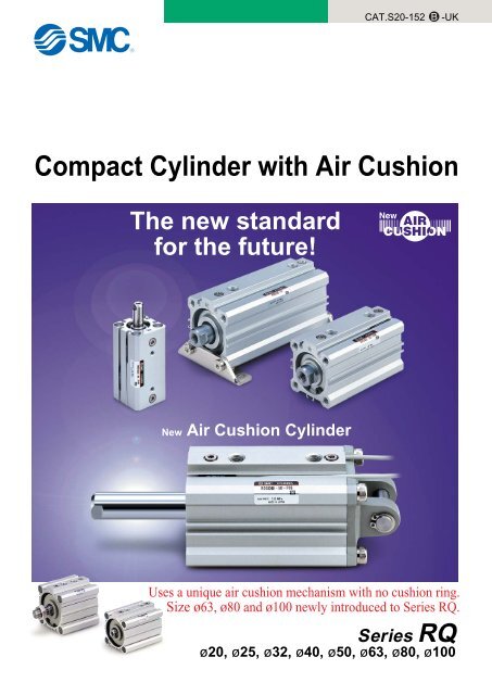
The new standard<br />
for the future!<br />
New Air Cushion Cylinder<br />
CAT.S20-152 B<br />
-UK<br />
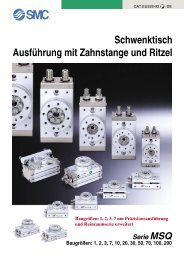
Compact Cylinder with Air Cushion<br />
Uses a unique air cushion mechanism with no cushion ring.<br />
Size ø63, ø80 and ø100 newly introduced to <strong>Series</strong> <strong>RQ</strong>.<br />
<strong>Series</strong> <strong>RQ</strong><br />
ø20, ø25, ø32, ø40, ø50, ø63, ø80, ø100
Future new standard for shock elimination,<br />
Wide size variations from ø20 to ø100<br />
New<br />
New<br />
New<br />
∗Size ø20 and ø25 have through holes and double end taps in common.<br />
Employs a new construction<br />
for the air cushion mechanism.<br />
Compact Cylinder with Air Cushion<br />
<strong>Series</strong> <strong>RQ</strong><br />
ø63, ø80 and ø100<br />
newly introduced!<br />
Operating<br />
principle<br />
Features 1<br />
New<br />
Debut of the air cushion series!!<br />
R H<br />
Piston<br />
seals<br />
A + A'<br />
A<br />
Model Counting<br />
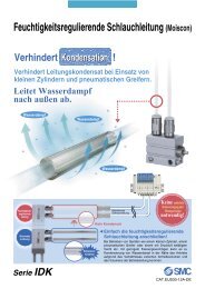
Unique air cushion construction with no cushion ring<br />
Elimination of the cushion ring used in conventional cushion ring type air cushions<br />
has made it possible to reduce the overall length of the cylinder. This produces an air<br />
cushion cylinder which retains the merits of a compact design.<br />
A'<br />
R(D)Q�20<br />
R(D)Q�25<br />
R(D)Q�32 �Through hole<br />
�Double end tapped<br />
R(D)Q�40 �Foot type<br />
�Front<br />
R(D)Q�50<br />
flange type<br />
�Rear flange type<br />
R(D)Q�63 �Double clevis type<br />
R(D)Q�80<br />
R(D)Q�100<br />
Rod end<br />
configuration<br />
� Female threads<br />
�Male threads<br />
A'<br />
R H<br />
A'<br />
Standard stroke Auto switch<br />
15 20 25 30 40 50 75 100<br />
qWhen the piston is retracting, exhaust is discharged<br />
from both A and A' until piston seal H<br />
passes the air passage A.<br />
wAfter piston seal H has passed the air passage<br />
A, exhaust is discharged only from A'. The section<br />
marked with diagonal lines becomes a<br />
cushion chamber, and a cushioning effect is<br />
achieved.<br />
eWhen air is supplied for piston extension, the<br />
check seal opens and the piston starts with no<br />
delay.<br />
�ø20 to ø100<br />
Direct mount<br />
auto switch<br />
�ø32 to ø100<br />
Rail mount<br />
auto switch
noise reduction and improvement in repeatability<br />
<strong>Series</strong> RDQ<br />
<strong>Series</strong> CDQS<br />
2.5 13<br />
(Compared with series CDQS/CDQ2 of the same bore size with auto switches)<br />
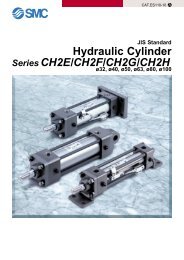
Minimal extended dimensions from +2.5mm to 13mm<br />
Extension<br />
Nearly three times the<br />
allowable kinetic energy<br />
(Compared to CQS/CQ2 with rubber bumper)<br />
Improved energy absorption allows selection of a cylinder that is<br />
two sizes smaller for the same kinetic energy.<br />
Allowable kinetic energy (J)<br />
10<br />
8<br />
6<br />
4<br />
2<br />
0<br />
<strong>Series</strong> <strong>RQ</strong><br />
CQ2/ with rubber bumper<br />
2.50<br />
4.00<br />
0.11<br />
20 25 32 40 50 63 80 100<br />
Bore size (mm)<br />
0.40 0.18 0.63 1.00<br />
0.29<br />
1.60<br />
0.52<br />
0.91<br />
1.54<br />
Improved noise reduction<br />
(Stroke end impact noise reduced)<br />
<strong>Series</strong><br />
<strong>Series</strong><br />
RDQ<br />
�Decrease of 19dB or more (compared with CQ2 without cushion)<br />
�Decrease of 14dB or more (compared with CQ2 with rubber bumper)<br />
2.71<br />
6.40<br />
4.51<br />
10.00<br />
Bore size<br />
20<br />
25<br />
32<br />
40<br />
50<br />
63<br />
80<br />
100<br />
Interchangeable<br />
mounting<br />
The mounting dimension "M" is the same as<br />
compact cylinder series CQS/CQ2 .<br />
(CQS/CQ2 mounting brackets can be used without any<br />
changes.)<br />
ø20, ø25 ø32 to ø100<br />
Mounting dimension M<br />
Extended<br />
dimension<br />
+2.5mm<br />
+4mm<br />
+4mm<br />
+4.5mm<br />
+9mm<br />
+9mm<br />
+10mm<br />
+13mm<br />
Comparable<br />
cylinder<br />
<strong>Series</strong><br />
CDQS<br />
<strong>Series</strong><br />
CDQ2<br />
Mounting dimension M<br />
Improved repeatability<br />
The piston contact surface at the stroke end is<br />
metal, providing improved repeatability for the<br />
stopping position as compared with a rubber<br />
bumper.<br />
Features 2
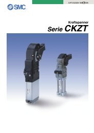
Without auto switch<br />
With auto switch<br />
B<br />
A<br />
L<br />
Through hole (standard)<br />
Double end tapped<br />
Foot<br />
With auto switch<br />
(built-in magnet)<br />
F<br />
G<br />
D<br />
<strong>RQ</strong> B 32<br />
RDQ B 32<br />
Mounting<br />
Front flange<br />
Rear flange<br />
Double clevis<br />
Note 1) Mounting brackets are packed together when shipped<br />
(unassembled).<br />
Note 2) Since sizes ø20 and ø25 have a body with B type<br />
(through hole) and A type (double end tapped) in<br />
common, there is no A type part number.<br />
Example) <strong>RQ</strong>A 20-30 does not exist.<br />
Bore size<br />
20 20mm<br />
25 25mm<br />
32 32mm<br />
40 40mm<br />
50 50mm<br />
63 63mm<br />
80 80mm<br />
100 100mm<br />
Type<br />
Reed switch<br />
Solid state switch<br />
Special<br />
function<br />
�<br />
Diagnostic indication<br />
(2-colour display)<br />
Electrical<br />
entry<br />
Grommet<br />
Connector<br />
Grommet<br />
Indicator light<br />
Yes<br />
Wiring<br />
(Output)<br />
3-wire<br />
(NPN equiv.)<br />
2-wire<br />
Load voltage<br />
DC AC<br />
�<br />
Grommet<br />
3-wire (NPN)<br />
3-wire (PNP)<br />
5V, 12V<br />
Connector<br />
2-wire 12V<br />
Diagnostic indication<br />
(2-colour display)<br />
3-wire (NPN)<br />
3-wire (PNP)<br />
Yes<br />
24V<br />
5V, 12V<br />
Water resistance Grommet<br />
(2-colour display)<br />
2-wire 12V<br />
With diagnostic output<br />
(2-colour display)<br />
4-wire<br />
5V, 12V<br />
Latch type with<br />
diagnostic output<br />
(2-colour display)<br />
(NPN)<br />
�<br />
�<br />
�<br />
24V<br />
5V �<br />
� 200V<br />
12V<br />
100V<br />
�<br />
�<br />
�<br />
How to Order<br />
50<br />
50 M9BW<br />
Port thread type<br />
Nil<br />
M thread<br />
Rc<br />
ø20, 25<br />
TN NPT ø32 to ø100<br />
TF G<br />
A72<br />
A73<br />
�<br />
A73C<br />
A79W<br />
F7NV<br />
F7PV<br />
F7BV<br />
J79C<br />
F7NWV<br />
�<br />
F7BWV<br />
�<br />
F7BAV<br />
�<br />
�<br />
Number of<br />
auto switches<br />
Nil 2 pcs.<br />
S 1 pc<br />
n "n" pcs.<br />
Auto switch<br />
Nil Without auto switch (built-in magnet)<br />
∗Select auto switch models from the table below.<br />
∗The auto switch is packed together when shipped<br />
(unmounted).<br />
Body option<br />
Nil Rod end female threads (standard)<br />
M Rod end male threads<br />
Cylinder stroke (mm)<br />
Refer to page 2 for standard strokes.<br />
Applicable auto switches/For detailed specifications of applicable auto switches, refer to pages 5.3-2 through 5.3-75 of "Best Pneumatics vol.2".<br />
∗Lead wire length symbols 0.5m ����� Nil (Example) A73C<br />
3 m ����� Z (Example) A73CL<br />
5 m ����� L (Example) A73CZ<br />
None ����� N (Example) A73CN<br />
Rail mount Direct mount<br />
ø32 to ø100 ø20 to ø100<br />
Perpendicular In-line Perpendicular In-line<br />
� A76H A96V A96<br />
A72H � �<br />
A73H � �<br />
� A93V A93<br />
� � �<br />
�<br />
F79<br />
F7P<br />
J79<br />
�<br />
F79W<br />
F7PW<br />
J79W<br />
F7BA<br />
�<br />
F79F<br />
F7LF<br />
�<br />
M9NV<br />
M9PV<br />
M9BV<br />
�<br />
M9NWV<br />
M9PWV<br />
M9BWV<br />
�<br />
�<br />
�<br />
�<br />
�<br />
M9N<br />
M9P<br />
M9B<br />
�<br />
M9NW<br />
M9PW<br />
M9BW<br />
M9BA<br />
�<br />
� Besides the models in the above catalog, there are some other auto switches that are applicable. For more information, refer to page 15.<br />
1<br />
Compact Cylinder with Air Cushion<br />
<strong>Series</strong> <strong>RQ</strong><br />
ø20, ø25, ø32, ø40, ø50, ø63, ø80, ø100<br />
�<br />
�<br />
Lead wire length (m)<br />
0.5<br />
(Nil)<br />
3<br />
(L)<br />
5 None<br />
(Z) (N)<br />
IC circuit �<br />
�<br />
Relay,<br />
PLC<br />
∗<br />
Pre-wired<br />
connector<br />
Applicable<br />
load<br />
� � � � �<br />
� � � � �<br />
� � � � �<br />
�<br />
�<br />
�<br />
�<br />
�<br />
�<br />
�<br />
�<br />
�<br />
�<br />
�<br />
�<br />
�<br />
�<br />
�<br />
�<br />
�<br />
�<br />
�<br />
�<br />
�<br />
�<br />
�<br />
�<br />
�<br />
�<br />
�<br />
�<br />
�<br />
�<br />
�<br />
�<br />
�<br />
�<br />
�<br />
�<br />
�<br />
�<br />
�<br />
�<br />
�<br />
�<br />
�<br />
�<br />
�<br />
�<br />
IC circuit<br />
�<br />
IC circuit<br />
�<br />
IC circuit<br />
�<br />
Relay,<br />
PLC<br />
∗Solid state auto switches marked with a "�" are produced<br />
upon receipt of order.<br />
�<br />
�<br />
�<br />
�<br />
�<br />
�<br />
�<br />
�<br />
�<br />
�<br />
�<br />
�<br />
�<br />
�<br />
�<br />
�<br />
�<br />
�<br />
�<br />
�<br />
�<br />
�<br />
�<br />
�
Allowable kinetic energy<br />
Refer to "Selection" on page 24 regarding<br />
the allowable kinetic energy.<br />
Effective Cushion Length<br />
Bore size (mm)<br />
Effective cushion<br />
length (mm)<br />
20<br />
25<br />
32<br />
40<br />
5.8 6.1 6.6 6.6 7.1<br />
Mounting Bracket Part No.<br />
Bore size<br />
(mm)<br />
20<br />
25<br />
32<br />
40<br />
50<br />
63<br />
80<br />
100<br />
50<br />
63<br />
7<br />
80 100<br />
7.5<br />
Note 1) Note 3)<br />
Foot Flange Double clevis<br />
CQS-L020<br />
CQS-L025<br />
CQ-L032<br />
CQ-L040<br />
CQ-L050<br />
CQ-L060<br />
CQ-L080<br />
CQ-L100<br />
CQS-F020<br />
CQS-F025<br />
CQ-F032<br />
CQ-F040<br />
CQ-F050<br />
CQ-F060<br />
CQ-F080<br />
CQ-F100<br />
8<br />
CQS-D020<br />
CQS-D025<br />
CQ-D032<br />
CQ-D040<br />
CQ-D050<br />
CQ-D060<br />
CQ-D080<br />
CQ-D100<br />
Note 1) When ordering foot brackets, order 2 pieces per cylinder.<br />
Note 2) The following parts are included with each bracket.<br />
Foot/Flange : Body mounting bolts.<br />
Double clevis: Clevis pins, C set ring for axis, and Body<br />
mounting bolts.<br />
Note 3) Clevis pins and snap rings are included with the double<br />
clevis type.<br />
Specifications<br />
Type<br />
Fluid<br />
Proof pressure<br />
Maximum operating pressure<br />
Minimum operating pressure<br />
Ambient and<br />
fluid temperature<br />
Rod end threads<br />
Rod end thread tolerance<br />
Stroke length tolerance<br />
Mounting<br />
Piston speed<br />
Standard Strokes<br />
Bore size (mm)<br />
20, 25<br />
32, 40<br />
50, 63<br />
80, 100<br />
Method<br />
Ordering<br />
Method<br />
Stroke range<br />
Example<br />
Theoretical Output<br />
Bore size (mm)<br />
20<br />
25<br />
32<br />
40<br />
50<br />
63<br />
80<br />
100<br />
Compact Cylinder with Air Cushion <strong>Series</strong> <strong>RQ</strong><br />
Operating<br />
direction<br />
IN<br />
OUT<br />
IN<br />
OUT<br />
IN<br />
OUT<br />
IN<br />
OUT<br />
IN<br />
OUT<br />
IN<br />
OUT<br />
IN<br />
OUT<br />
IN<br />
OUT<br />
Pneumatic (non-lube) type<br />
Air<br />
1.5MPa<br />
1.0MPa<br />
0.05MPa<br />
Without auto switch: �10<br />
Female threads<br />
JIS class 2<br />
�C to 70�C (with no freezing)<br />
With auto switch : �10�C to 60�C (with no freezing)<br />
+1.0<br />
0<br />
Through hole<br />
50 to 500mm/s<br />
Standard stroke (mm)<br />
15, 20, 25, 30, 40, 50<br />
20, 25, 30, 40, 50, 75, 100<br />
30, 40, 50, 75, 100<br />
40, 50, 75, 100<br />
Manufacture of Intermediate Strokes<br />
Special body type<br />
Refer to "How to Order" for standard part numbers.<br />
Available in stroke increments of 1mm, using a special body for the specified stroke.<br />
Bore size<br />
20, 25<br />
32, 40<br />
50, 63<br />
80, 100<br />
Part number: <strong>RQ</strong>B32-47<br />
A special tube is manufactured for a 47mm stroke.<br />
0.3<br />
71<br />
94<br />
113<br />
147<br />
181<br />
241<br />
317<br />
377<br />
495<br />
589<br />
841<br />
935<br />
1360<br />
1510<br />
2140<br />
2360<br />
OUT IN<br />
Operating pressure (MPa)<br />
0.5<br />
118<br />
157<br />
189<br />
245<br />
302<br />
402<br />
528<br />
628<br />
825<br />
982<br />
1400<br />
1560<br />
2270<br />
2510<br />
3570<br />
3930<br />
Stroke range<br />
16 to 49<br />
21 to 99<br />
31 to 99<br />
41 to 99<br />
0.7<br />
165<br />
220<br />
264<br />
344<br />
422<br />
563<br />
739<br />
880<br />
1150<br />
1370<br />
1960<br />
2180<br />
3170<br />
3520<br />
5000<br />
5500<br />
Unit: N<br />
2
<strong>Series</strong> <strong>RQ</strong><br />
Weights<br />
Basic weights Unit: g Additional weights<br />
Bore size (mm)<br />
20<br />
25<br />
32<br />
40<br />
50<br />
63<br />
80<br />
100<br />
Mounting<br />
15<br />
141<br />
203<br />
�<br />
�<br />
�<br />
�<br />
�<br />
�<br />
20<br />
156<br />
221<br />
271<br />
390<br />
�<br />
�<br />
�<br />
�<br />
Standard stroke (mm)<br />
25<br />
171<br />
239<br />
291<br />
413<br />
�<br />
�<br />
�<br />
�<br />
30<br />
186<br />
258<br />
312<br />
436<br />
731<br />
940<br />
�<br />
�<br />
40<br />
216<br />
294<br />
353<br />
482<br />
803<br />
1019<br />
1819<br />
2859<br />
50<br />
245<br />
331<br />
394<br />
528<br />
875<br />
1099<br />
1950<br />
3038<br />
Through hole type mounting bolts for <strong>RQ</strong>B are available.<br />
How to order: Add "Bolt" in front of the bolts to be used.<br />
Example) Bolt M5 x 50l 4 pcs.<br />
Model C<br />
R(D)QB20-15<br />
-20<br />
-25<br />
9<br />
-30<br />
-40<br />
-50<br />
R(D)QB25-15<br />
-20<br />
-25<br />
9.5<br />
-30<br />
-40<br />
-50<br />
R(D)QB32-20<br />
-25<br />
-30<br />
-40 10<br />
-50<br />
-75<br />
-100<br />
3<br />
D<br />
50<br />
55<br />
60<br />
65<br />
75<br />
85<br />
55<br />
60<br />
65<br />
70<br />
80<br />
90<br />
60<br />
65<br />
70<br />
80<br />
90<br />
115<br />
140<br />
75<br />
�<br />
�<br />
496<br />
643<br />
1055<br />
1297<br />
2278<br />
3483<br />
Mounting bolt<br />
M5 x 50l<br />
x 55l<br />
x 60l<br />
x 65l<br />
x 75l<br />
x 85l<br />
M5 x 55l<br />
x 60l<br />
x 65l<br />
x 70l<br />
x 80l<br />
x 90l<br />
M5 x 60l<br />
x 65l<br />
x 70l<br />
x 80l<br />
x 90l<br />
x 115l<br />
x 140l<br />
100<br />
�<br />
�<br />
598<br />
758<br />
1235<br />
1495<br />
2606<br />
3928<br />
Bore size (mm)<br />
Magnet<br />
Double end tapped<br />
Rod end<br />
male threads<br />
Male threads<br />
Nut<br />
Foot (including bolt)<br />
Front flange (including bolt)<br />
Rear flange (including bolt)<br />
Double clevis (including pin, snap ring and bolt)<br />
Calculation example) <strong>RQ</strong>D32-20M<br />
�Basic weight : <strong>RQ</strong>B32-20 271g<br />
�Additional weight: Double end tapped 6g<br />
Rod end male threads 43g<br />
Double clevis 151g<br />
471g<br />
Model C<br />
R(D)QB40-20<br />
-25<br />
-30<br />
-40 8<br />
-50<br />
-75<br />
-100<br />
R(D)QB50-30<br />
-40<br />
-50 13.5<br />
-75<br />
-100<br />
R(D)QB63-30<br />
-40<br />
-50 15.5<br />
-75<br />
-100<br />
R(D)QB80-40<br />
-50<br />
15<br />
-75<br />
-100<br />
R(D)QB100-40<br />
-50<br />
17.5<br />
-75<br />
-100<br />
20<br />
5<br />
�<br />
6<br />
4<br />
159<br />
143<br />
137<br />
92<br />
25<br />
6<br />
�<br />
12<br />
8<br />
181<br />
180<br />
171<br />
127<br />
D<br />
D<br />
65<br />
70<br />
75<br />
85<br />
95<br />
120<br />
145<br />
85<br />
95<br />
105<br />
130<br />
155<br />
90<br />
100<br />
110<br />
135<br />
160<br />
105<br />
115<br />
140<br />
165<br />
120<br />
130<br />
155<br />
180<br />
32<br />
11<br />
6<br />
26<br />
17<br />
143<br />
180<br />
165<br />
151<br />
C<br />
40<br />
13<br />
6<br />
27<br />
17<br />
155<br />
214<br />
198<br />
196<br />
50<br />
14<br />
6<br />
53<br />
32<br />
243<br />
373<br />
348<br />
393<br />
Mounting bolt<br />
63<br />
22<br />
19<br />
53<br />
32<br />
324<br />
559<br />
534<br />
554<br />
80<br />
24<br />
45<br />
120<br />
49<br />
696<br />
1056<br />
1017<br />
1109<br />
Mounting bolt<br />
M5 x 65l<br />
x 70l<br />
x 75l<br />
x 85l<br />
x 95l<br />
x 120l<br />
x 145l<br />
M6 x 85l<br />
x 95l<br />
x 105l<br />
x 130l<br />
x 155l<br />
M8 x 90l<br />
x 100l<br />
x 110l<br />
x 135l<br />
x 160l<br />
M10 x 105l<br />
x 115l<br />
x 140l<br />
x 165l<br />
M10 x 120l<br />
x 130l<br />
x 155l<br />
x 180l<br />
Unit: g<br />
100<br />
35<br />
45<br />
175<br />
116<br />
1062<br />
1365<br />
1309<br />
1887
Replacement Parts/Seal Kits<br />
<strong>Series</strong> Contents<br />
<strong>RQ</strong><br />
Bore size<br />
20<br />
25<br />
32<br />
40<br />
50<br />
63<br />
80<br />
100<br />
Order number<br />
<strong>RQ</strong>B20-PS<br />
<strong>RQ</strong>B25-PS<br />
<strong>RQ</strong>B32-PS<br />
<strong>RQ</strong>B40-PS<br />
<strong>RQ</strong>B50-PS<br />
<strong>RQ</strong>B63-PS<br />
<strong>RQ</strong>B80-PS<br />
<strong>RQ</strong>B100-PS<br />
Kits consist of<br />
piston seal,<br />
rod seal and gasket<br />
Compact Cylinder with Air Cushion <strong>Series</strong> <strong>RQ</strong><br />
Auto Switch Mounting Bracket Part Nos.<br />
Bore size<br />
(mm)<br />
32, 40,<br />
50, 63,<br />
80, 100<br />
Bracket<br />
no.<br />
BQ-2<br />
Note<br />
� Switch mounting<br />
screw (M3 x 0.5 x 10l)<br />
�Switch spacer<br />
�Switch mounting nut<br />
Applicable switch<br />
Reed switch Solid state switch<br />
D-A7�, A80<br />
D-A73C, A80C<br />
D-A7�H, A80H<br />
D-A79W<br />
D-F7�, J79<br />
D-F7�V<br />
D-J79C<br />
D-F7�W, J79W<br />
D-F7�WV<br />
D-F7BAL<br />
D-F7BAVL<br />
D-F7�F<br />
D-F7NTL<br />
[Stainless steel mounting screw kit]<br />
Use the following stainless steel mounting screw kit (includes nut) depending on the<br />
operating environment.<br />
(Auto switch spacer must be ordered separately.<br />
BBA2: For D-A7/A8/F7/J7<br />
The above stainless steel screw kit is used for water resistant auto switch types<br />
D-F7BAL and D-F7BAVL when they are shipped mounted on a cylinder.<br />
Also, BBA2 is included when an auto switch alone is shipped.<br />
4
<strong>Series</strong> <strong>RQ</strong><br />
Dimensions/ ø20, ø25 ∗Refer to page13 for proper auto switch mounting positions and height.<br />
Standard type (through hole, double end tapped common)/<strong>RQ</strong>B, RDQB<br />
∗Rod end nut<br />
Bore size (mm)<br />
20<br />
25<br />
1<br />
H1<br />
Standard type<br />
Rod end male threads<br />
øD<br />
Flat washer<br />
4 pcs.<br />
C1<br />
X<br />
L1<br />
Stroke range (mm)<br />
15 to 50<br />
15 to 50<br />
L<br />
A<br />
36.5<br />
41.5<br />
2 x M5 (port size)<br />
Q<br />
B<br />
32<br />
36.5<br />
B + Stroke<br />
A + Stroke<br />
C<br />
7<br />
12<br />
∗Refer to page 11 for details on rod end nut and accessories.<br />
5<br />
D<br />
10<br />
12<br />
� Add the stroke to calculate the length of intermediate strokes.<br />
F<br />
E<br />
36<br />
40<br />
2-cushion needle<br />
E1<br />
18<br />
20<br />
4-ø5.4 through<br />
2 x 4-ø9 depth of<br />
counter bore 7<br />
Rod end male threads<br />
Bore size<br />
(mm)<br />
20<br />
25<br />
E2<br />
21<br />
23.5<br />
F<br />
15.5<br />
17<br />
C1<br />
12<br />
15<br />
H<br />
M5<br />
M6<br />
E1 E2<br />
X<br />
14<br />
17.5<br />
K<br />
8<br />
10<br />
K<br />
M<br />
W<br />
L<br />
4.5<br />
5<br />
H1<br />
M8<br />
M10 x 1.25<br />
M<br />
25.5<br />
28<br />
H thread effective<br />
depth C<br />
M<br />
2 x 4 x M6<br />
effective depth 10<br />
Q<br />
21<br />
23<br />
E<br />
L1<br />
18.5<br />
22.5<br />
mm<br />
mm<br />
W<br />
39<br />
43.5
Mounting Bracket Dimensions<br />
Foot type/<strong>RQ</strong>L, RDQL<br />
Rod end<br />
nut ∗<br />
Front flange type/ <strong>RQ</strong>F, RDQF<br />
Rod end<br />
nut ∗<br />
L1<br />
L1<br />
L<br />
Rear flange type/<strong>RQ</strong>G, RDQG<br />
Rod end male threads<br />
B + Stroke<br />
3.2<br />
X 5.8 5.8 X 4<br />
LS + Stroke<br />
A + Stroke<br />
Double clevis/<strong>RQ</strong>D, DQD<br />
Rod end male threads<br />
Rod end male threads<br />
8<br />
FX<br />
L B + Stroke<br />
FZ<br />
A + Stroke<br />
Rear flange type<br />
Double clevis type Applicable<br />
}<br />
FX<br />
FZ<br />
CX<br />
CZ<br />
+0.4<br />
+0.2<br />
�0.1<br />
�0.3<br />
L<br />
FV<br />
FW<br />
2-ø6.6<br />
Special cap bolt<br />
L1<br />
L<br />
LX<br />
LZ<br />
Rod end nut ∗<br />
B + Stroke<br />
A + Stroke<br />
5 CU<br />
B + Stroke CW RR<br />
CL + Stroke<br />
A + Stroke<br />
Cap bolt<br />
LH<br />
FV<br />
FW<br />
LY<br />
4-ø6.6<br />
2-ø6.6<br />
8<br />
øCD hole H10<br />
Shaft d9<br />
Compact Cylinder with Air Cushion <strong>Series</strong> <strong>RQ</strong><br />
Foot type<br />
Bore size Stroke range<br />
(mm) (mm)<br />
20 15 to 50<br />
25 15 to 50<br />
Bore size<br />
(mm)<br />
B<br />
A LS L L1<br />
53.7<br />
58.7<br />
LH LX<br />
20<br />
21.5<br />
14.5<br />
15<br />
LY LZ<br />
28.5<br />
32.5<br />
20 32 24 48 45 62 9.2<br />
25 36.5 26 52 49.5 66 10.7<br />
(All dimensions but A, LS, L and L1 are identical to those of the standard type.)<br />
Foot bracket material: Carbon steel<br />
Front flange type<br />
Bore size Stroke range<br />
(mm) (mm)<br />
20 15 to 50<br />
25 15 to 50<br />
Bore size<br />
(mm)<br />
20<br />
25<br />
Rear flange type<br />
Bore size<br />
(mm)<br />
20<br />
25<br />
Bore size<br />
(mm)<br />
20<br />
25<br />
Stroke range<br />
(mm)<br />
15 to 50<br />
15 to 50<br />
B<br />
32<br />
36.5<br />
Double clevis type<br />
Bore size Stroke range<br />
(mm) (mm)<br />
20 15 to 50<br />
25 15 to 50<br />
Bore size<br />
(mm)<br />
20<br />
25<br />
B<br />
32<br />
36.5<br />
B<br />
32<br />
36.5<br />
L<br />
4.5<br />
5<br />
4.5<br />
5<br />
A<br />
44.5<br />
49.5<br />
L FV<br />
A<br />
63.5<br />
71.5<br />
18.5<br />
22.5<br />
A L L1<br />
46.5<br />
51.5<br />
FV FW<br />
39<br />
42<br />
39<br />
42<br />
L1 CD<br />
8<br />
10<br />
40.5<br />
44.5<br />
CL<br />
54.5<br />
61.5<br />
CU<br />
12<br />
14<br />
14.5<br />
15<br />
FW FX<br />
40.5<br />
44.5<br />
18<br />
20<br />
48<br />
52<br />
48<br />
52<br />
CW CX<br />
8<br />
10<br />
CZ<br />
28.5<br />
32.5<br />
16<br />
20<br />
X<br />
FX FZ<br />
60<br />
64<br />
(All dimensions but A, L and L1 are identical to those of the standard type.)<br />
Flange material: Carbon steel<br />
mm<br />
FZ<br />
60<br />
64<br />
(All dimensions but A is identical to those of the standard type.)<br />
Flange material: Carbon steel<br />
(All dimensions but A and CL are identical to those of the standard type.)<br />
∗Refer to page 11 for details on rod end nut and accessories.<br />
Double clevis bracket material: Carbon steel<br />
mm<br />
RR<br />
mm<br />
mm<br />
mm<br />
mm<br />
mm<br />
mm<br />
9<br />
10<br />
6
<strong>Series</strong> <strong>RQ</strong><br />
Dimensions/ø32, ø40, ø50<br />
Standard type (through hole type)/<strong>RQ</strong>B, RDQB<br />
H1<br />
øD<br />
OA threads<br />
C1<br />
X<br />
L1<br />
Bore size (mm)<br />
32<br />
40<br />
50<br />
L<br />
Standard type<br />
Rod end nut ∗<br />
Stroke range (mm)<br />
20 to 100<br />
20 to 100<br />
30 to 100<br />
B + Stroke<br />
A + Stroke<br />
A<br />
44<br />
51<br />
57.5<br />
2-P<br />
(Port size)<br />
B<br />
37<br />
44<br />
49.5<br />
∗Refer to page 11 for details on rod end nut and accessories.<br />
7<br />
Bore size (mm)<br />
32<br />
40<br />
50<br />
RA RA<br />
Q<br />
Rod end male threads<br />
OB<br />
9<br />
9<br />
11<br />
P<br />
1/8<br />
1/8<br />
1/4<br />
Q<br />
23<br />
28<br />
31.5<br />
RB<br />
C<br />
13<br />
13<br />
15<br />
2-cushion needle<br />
� Add the stroke to calculate the length of intermediate strokes.<br />
7<br />
7<br />
8<br />
F<br />
S<br />
58.5<br />
66<br />
80<br />
D<br />
16<br />
16<br />
20<br />
U<br />
31.5<br />
35<br />
41<br />
Minimum bending<br />
radius for lead wire 10<br />
E<br />
45<br />
52<br />
64<br />
22<br />
11<br />
mm<br />
Z<br />
14<br />
14<br />
19<br />
∗Refer to pages 13 and 14 for proper auto switch mounting positions and height.<br />
Auto switch<br />
D-A7, A8<br />
F<br />
18.5<br />
20<br />
28.5<br />
Double end tapped type: <strong>RQ</strong>A, RDQA<br />
øI<br />
H<br />
M8<br />
M8<br />
M10<br />
Double end tapped<br />
Bore size<br />
(mm)<br />
32<br />
40<br />
50<br />
Approx. U<br />
Bore size<br />
(mm)<br />
32<br />
40<br />
50<br />
I<br />
60<br />
69<br />
86<br />
J<br />
4.5<br />
5<br />
7<br />
K<br />
M<br />
E<br />
S<br />
C1<br />
20.5<br />
20.5<br />
26<br />
OA<br />
M6<br />
M6<br />
M8<br />
Rod end male threads<br />
X<br />
23.5<br />
23.5<br />
28.5<br />
K<br />
14<br />
14<br />
17<br />
H thread effective depth C<br />
4-øN through<br />
2 x 4-øOB depth<br />
of counter bore RB<br />
Auto switch<br />
D-A9, F9<br />
L<br />
7<br />
7<br />
8<br />
RA<br />
10<br />
10<br />
14<br />
mm<br />
Z<br />
M<br />
J<br />
H1<br />
M14 x 1.5<br />
M14 x 1.5<br />
M18 x 1.5<br />
M<br />
34<br />
40<br />
50<br />
E<br />
L1<br />
mm<br />
28.5<br />
28.5<br />
33.5<br />
mm<br />
N<br />
5.5<br />
5.5<br />
6.6
Mounting Bracket Dimensions<br />
Foot type/<strong>RQ</strong>L, RDQL<br />
Rod end<br />
nut<br />
Front flange type/<strong>RQ</strong>F, RDQF<br />
Rod end<br />
nut<br />
Rear flange type/<strong>RQ</strong>G, RDQG<br />
Rod end male threads<br />
Rod end male threads<br />
FT<br />
L B + Stroke<br />
FX<br />
A + Stroke<br />
FZ<br />
Rod end male threads<br />
Rear flange type<br />
Double clevis type Applicable<br />
FV<br />
M<br />
L1<br />
L<br />
L1<br />
Double clevis type/<strong>RQ</strong>D, RDQD<br />
CX +0.4<br />
+0.2<br />
�0.1<br />
�0.3<br />
CZ<br />
X<br />
B + Stroke<br />
Y Y<br />
LS + Stroke<br />
A + Stroke<br />
FX<br />
FZ<br />
3.2<br />
}<br />
L<br />
4-øFD<br />
X LG<br />
B + Stroke<br />
CL + Stroke<br />
A + Stroke<br />
Special<br />
cap bolt<br />
L1<br />
Rod end nut<br />
L<br />
CT<br />
B + Stroke<br />
A + Stroke<br />
CU<br />
CW RR<br />
LX<br />
LZ<br />
M<br />
FV<br />
4-øFD<br />
4-N<br />
Cap bolt<br />
øCD hole H10<br />
Shaft d9<br />
FT<br />
Compact Cylinder with Air Cushion <strong>Series</strong> <strong>RQ</strong><br />
LH<br />
LY<br />
4-øLD<br />
Foot type<br />
Bore size<br />
(mm)<br />
32<br />
40<br />
50<br />
Bore size<br />
(mm)<br />
32<br />
40<br />
50<br />
Stroke range<br />
(mm)<br />
20 to 100<br />
20 to 100<br />
30 to 100<br />
LG<br />
4<br />
4<br />
5<br />
Rear flange type<br />
Bore size<br />
(mm)<br />
32<br />
40<br />
50<br />
LH<br />
30<br />
33<br />
39<br />
Front flange type<br />
Bore size Stroke range<br />
(mm) (mm)<br />
32 20 to 100<br />
40 20 to 100<br />
50 30 to 100<br />
Bore size<br />
(mm)<br />
32<br />
40<br />
50<br />
FX<br />
56<br />
62<br />
76<br />
Stroke range<br />
(mm)<br />
20 to 100<br />
20 to 100<br />
30 to 100<br />
Double clevis type<br />
Bore size Stroke range<br />
(mm) (mm)<br />
32 20 to 100<br />
40 20 to 100<br />
50 30 to 100<br />
A<br />
61.2<br />
68.2<br />
75.7<br />
65<br />
72<br />
89<br />
A<br />
A<br />
74<br />
83<br />
99.5<br />
LX<br />
57<br />
64<br />
79<br />
54<br />
61<br />
67.5<br />
A<br />
52<br />
59<br />
66.5<br />
B LS L L1<br />
37<br />
44<br />
49.5<br />
FZ L<br />
17<br />
17<br />
18<br />
B<br />
37<br />
44<br />
49.5<br />
57<br />
64<br />
78<br />
21<br />
28<br />
26.5<br />
LY LZ<br />
37<br />
44<br />
49.5<br />
CL<br />
64<br />
73<br />
85.5<br />
71<br />
78<br />
95<br />
L<br />
7<br />
7<br />
8<br />
17<br />
17<br />
18<br />
CD<br />
10<br />
10<br />
14<br />
11.2<br />
11.2<br />
14.7<br />
38.5<br />
38.5<br />
43.5<br />
X Y<br />
CT<br />
5<br />
6<br />
7<br />
5.8<br />
7<br />
8<br />
L1<br />
28.5<br />
28.5<br />
33.5<br />
LD<br />
6.6<br />
6.6<br />
9<br />
Bore size<br />
(mm)<br />
CW CX CZ L L1 N<br />
mm<br />
RR<br />
32 20 18 36 7 28.5 M6 10<br />
40 22 18 36 7 28.5 M6 10<br />
50 28 22 44 8 33.5 M8 14<br />
∗Refer to page 11 for details on rod end nut and accessories.<br />
∗Clevis pins and snap rings are included in the package.<br />
Double clevis bracket material: carbon steel<br />
B<br />
38.5<br />
38.5<br />
43.5<br />
FD<br />
5.5<br />
5.5<br />
6.6<br />
L1 M<br />
34<br />
40<br />
50<br />
FT<br />
8<br />
8<br />
9<br />
mm<br />
mm<br />
FV<br />
48<br />
54<br />
67<br />
CU<br />
14<br />
14<br />
20<br />
mm<br />
Foot bracket material: Carbon steel<br />
mm<br />
Flange material: Carbon steel<br />
mm<br />
(∗All dimensions but A, L and L1 are identical to those of the front flange type.)<br />
Flange material: Carbon steel<br />
mm<br />
8
<strong>Series</strong> <strong>RQ</strong><br />
Dimensions/ø63 to ø100<br />
Standard type (through hole type)<br />
OA threads RA RA<br />
H1<br />
øD<br />
C1<br />
X<br />
L1<br />
L<br />
Q<br />
B + Stroke<br />
A + Stroke<br />
Rod end male thread<br />
Rod end nut ∗<br />
F<br />
2-P<br />
(Port size)<br />
2-cushion needle<br />
22<br />
11<br />
Minimum bending<br />
radius for lead wire 10<br />
øI<br />
Auto switch<br />
D-A7, A8<br />
Approx. U<br />
K<br />
M<br />
E<br />
S<br />
H thread effective depth C<br />
4-øN through<br />
2 x 4-øOB depth<br />
of counter bore RB<br />
Z<br />
M<br />
E<br />
J<br />
Auto switch<br />
D-A9, F9<br />
63 26 28.5 M18 x 1.5 33.5<br />
80 32.5 35.5 M22 x 1.5 43.5<br />
100 32.5 35.5 M26 x 1.5 43.5<br />
Standard type mm<br />
Bore size<br />
(mm)<br />
63<br />
80<br />
100<br />
Bore size (mm)<br />
63<br />
80<br />
100<br />
Stroke range<br />
(mm)<br />
30 to 100<br />
40 to 100<br />
40 to 100<br />
Q<br />
34<br />
39<br />
43<br />
RB<br />
10.5<br />
13.5<br />
13.5<br />
A<br />
63<br />
73.5<br />
88<br />
B<br />
55<br />
63.5<br />
76<br />
S<br />
93<br />
112.5<br />
132.5<br />
C<br />
15<br />
21<br />
27<br />
U<br />
47.5<br />
57.5<br />
67.5<br />
D<br />
20<br />
25<br />
30<br />
∗Refer to page 11 for details on rod end nut and accessories.<br />
9<br />
E<br />
77<br />
98<br />
117<br />
mm<br />
Z<br />
19<br />
26<br />
26<br />
� Add the stroke to calculate the length of intermediate strokes.<br />
F<br />
31<br />
35.5<br />
40<br />
∗Refer to pages 13 and 14 for proper auto switch mounting positions and height.<br />
Double end tapped mm<br />
H<br />
M10<br />
M16<br />
M20<br />
Bore size<br />
(mm)<br />
63<br />
80<br />
100<br />
Double end tapped type: <strong>RQ</strong>A, RDQA<br />
I<br />
103<br />
132<br />
156<br />
J<br />
7<br />
6<br />
6.5<br />
OA<br />
M10<br />
M12<br />
M12<br />
Bore size<br />
(mm)<br />
K<br />
17<br />
22<br />
27<br />
L<br />
8<br />
10<br />
12<br />
C1<br />
RA<br />
18<br />
22<br />
22<br />
Rod end male threads mm<br />
M<br />
60<br />
77<br />
94<br />
X<br />
N<br />
9<br />
11<br />
11<br />
H1<br />
OB<br />
14<br />
17.5<br />
17.5<br />
P<br />
1/4<br />
3/8<br />
3/8<br />
L1
Mounting Bracket Dimensions<br />
Foot type/<strong>RQ</strong>L, RDQL<br />
Rod end<br />
nut<br />
Rod end<br />
nut<br />
FV<br />
M<br />
L1<br />
L<br />
L1<br />
L<br />
FT<br />
B + Stroke<br />
FX<br />
A + Stroke<br />
FZ<br />
FX<br />
FZ<br />
CX<br />
CZ<br />
B + Stroke<br />
X Y YX<br />
LG<br />
LS + Stroke<br />
A + Stroke<br />
+0.4<br />
+0.2<br />
�0.1<br />
�0.3<br />
LT<br />
L<br />
4-øFD<br />
L1<br />
Rod end nut<br />
Special<br />
cap bolt<br />
Front flange type/<strong>RQ</strong>F, RDQF<br />
Rear flange type/<strong>RQ</strong>G, RDQG<br />
L1<br />
Rod end nut<br />
Double clevis type/<strong>RQ</strong>D, RDQD<br />
Rod end<br />
male threads<br />
Rod end male threads<br />
Rod end<br />
male threads<br />
Rod end male threads<br />
L<br />
CT<br />
B + Stroke<br />
CL + Stroke<br />
A + Stroke<br />
B + Stroke<br />
A + Stroke<br />
M<br />
FV<br />
4-øFD<br />
FT<br />
4-N<br />
Cap bolt<br />
øCD hole H10<br />
Shaft d9<br />
CU<br />
CW RR<br />
LX<br />
LZ<br />
LH<br />
Compact Cylinder with Air Cushion <strong>Series</strong> <strong>RQ</strong><br />
LY<br />
4-øLD<br />
Foot type mm<br />
A B LS L L1 LD LG LH LT<br />
Bore size<br />
(mm)<br />
63<br />
80<br />
100<br />
Bore size<br />
(mm)<br />
63<br />
80<br />
100<br />
Bore size<br />
(mm)<br />
63<br />
80<br />
100<br />
Stroke range<br />
(mm)<br />
30 to 100 81.2 55<br />
40 to 100 95 63.5<br />
40 to 100 111 76<br />
Stroke range<br />
(mm)<br />
10 to 50<br />
75, 100<br />
10 to 50<br />
75, 100<br />
10 to 50<br />
75, 100<br />
Stroke range<br />
(mm)<br />
30 to 100<br />
40 to 100<br />
40 to 100<br />
LX<br />
LY<br />
29<br />
33.5<br />
42<br />
LZ<br />
95 91.5 113<br />
118 114 140<br />
137 136 162<br />
A<br />
B<br />
73 55<br />
83.5 63.5<br />
98 76<br />
FD<br />
9<br />
11<br />
11<br />
18<br />
20<br />
22<br />
X<br />
16.2<br />
19.5<br />
23<br />
FT<br />
9<br />
11<br />
11<br />
43.5<br />
53.5<br />
53.5<br />
FV<br />
Y<br />
9<br />
11<br />
12.5<br />
FX<br />
80 92<br />
99 116<br />
117 136<br />
11<br />
13<br />
13<br />
FZ<br />
108<br />
134<br />
154<br />
5<br />
7<br />
7<br />
L<br />
18<br />
20<br />
22<br />
46<br />
59<br />
71<br />
L1<br />
43.5<br />
53.5<br />
53.5<br />
3.2<br />
4.5<br />
6<br />
Front flange type mm<br />
Rear flange type mm<br />
Bore size<br />
(mm)<br />
63<br />
80<br />
100<br />
Stroke range<br />
(mm)<br />
30 to 100<br />
40 to 100<br />
40 to 100<br />
A<br />
72<br />
84.5<br />
99<br />
L<br />
8<br />
10<br />
12<br />
L1<br />
33.5<br />
43.5<br />
43.5<br />
Double clevis type mm<br />
Bore size<br />
(mm)<br />
Stroke range<br />
(mm)<br />
A B CL CD CT CU CW CX CZ L<br />
63 30 to 100 107 55 93 14 8 20 30 22 44 8<br />
80 40 to 100 129.5 63.5 111.5 18 10 27 38 28 56 10<br />
100 40 to 100 155 76 133 22 13 31 45 32 64 12<br />
Bore size<br />
(mm)<br />
63<br />
80<br />
100<br />
Stroke range<br />
(mm)<br />
10 to 50<br />
75, 100<br />
10 to 50<br />
75, 100<br />
10 to 50<br />
75, 100<br />
L1<br />
33.5<br />
43.5<br />
43.5<br />
N<br />
M10<br />
M12<br />
M12<br />
RR<br />
14<br />
∗Refer to page 11 for details on rod end nut and accessories.<br />
∗Clevis pins and snap rings are included in the package.<br />
18<br />
22<br />
M<br />
60<br />
77<br />
94<br />
10
<strong>Series</strong> <strong>RQ</strong><br />
Accessories<br />
Single Knuckle Joint Double Knuckle Joint<br />
For I-G02, I-G03 For I-G04, I-G05 For Y-G02, Y-G03 For Y-G04, Y-G05<br />
E1<br />
MM<br />
A1 U1<br />
NX L1<br />
A<br />
NX<br />
Applicable<br />
Part no.<br />
bore size (mm)<br />
A A1 E1 L1 MM RR1 U1 ND<br />
mm<br />
NX<br />
I-G02 20 34 8.5 �16 25 M8 10.3 11.5<br />
+0.058<br />
8 0<br />
�0.2<br />
8�0.4<br />
I-G03 25 41 10.5 �20 30 M10 x 1.25 12.8 14<br />
+0.058 �0.2<br />
10 0 10�0.4<br />
I-G04 32, 40 42 14 ø22 30 M14 x 1.5 12 14<br />
+0.058 �0.3<br />
10 0 18�0.5<br />
I-G05 50, 63 56 18 ø28 40 M18 x 1.5 16 20<br />
+0.070 �0.3<br />
14 0 22�0.5<br />
I-G08 80 71 21 ø38 50 M22 x 1.5 21 27<br />
+0.070 �0.3<br />
18 0 28�0.5<br />
I-G10 100 79 21 ø44 55 M26 x 1.5 24 31<br />
+0.084 �0.3<br />
22 32<br />
0<br />
Knuckle Pin (common with double clevis pin) Rod End Nut<br />
Material: Carbon steel<br />
mm<br />
Part no.<br />
Applicable<br />
bore size (mm)<br />
D L d l m t Snap ring<br />
IY-G02 20<br />
�0.040<br />
8 �0.076 21 7.6 16.2 1.5 0.9 C8 type for pivot<br />
IY-G03 25<br />
�0.040<br />
10 �0.076 25.6 9.6 20.2 1.55 1.15 C10 type for pivot<br />
IY-G04 32,40<br />
�0.040<br />
10 �0.076 41.6 9.6 36.2 1.55 1.15 C10 type for pivot<br />
IY-G05 50,63<br />
�0.050<br />
14 �0.093 50.6 13.4 44.2 2.05 1.15 C14 type for pivot<br />
IY-G08 80<br />
�0.050<br />
18 �0.093 64 17 56.2 2.55 1.35 C18 type for pivot<br />
IY-G10 100<br />
�0.065<br />
22 72 21 64.2 2.55 1.35 C22 type for pivot<br />
11<br />
Material: Carbon steel<br />
m<br />
t<br />
øNDH10<br />
RR1<br />
�0.117<br />
E1<br />
ød<br />
øDd9<br />
l m<br />
L t<br />
MM øNDH10<br />
A1 U1<br />
L1<br />
A<br />
RR1<br />
Material: Cast iron Material: Carbon steel Material: Cast iron<br />
�0.5<br />
L<br />
NX<br />
NZ<br />
Part no.<br />
Applicable A<br />
bore size (mm)<br />
A1 E1 L1 MM RR1 U1 ND<br />
mm<br />
NZ L<br />
Applicable<br />
NX<br />
pin no.<br />
Y-G02 20 34 8.5 �16 25 M8 10.3 11.5 +0.058 8 0<br />
+0.4<br />
8 +0.2 16 21 IY-G02<br />
Y-G03 25 41 10.5 �20 30 M10 x 1.25<br />
+0.058 +0.4<br />
12.8 14 10 0 10 +0.2 20 25.6 IY-G03<br />
Y-G04 32, 40 42 16 ø22 30 M14 x 1.5<br />
+0.058 +0.5<br />
12 14 10 0 18 +0.3 36 41.6 IY-G04<br />
Y-G05 50, 63 56 20 ø28 40 M18 x 1.5<br />
+0.070 +0.5<br />
16 20 14 0 22 +0.3 44 50.6 IY-G05<br />
Y-G08 80 71 23 ø38 50 M22 x 1.5<br />
+0.070 +0.5<br />
21 27 18 0 28 +0.3 56 64 IY-G08<br />
Y-G10 100 79 24 ø44 55 M26 x 1.5<br />
+0.084 +0.5<br />
24 31 22 0 32 +0.3 64 72 IY-G10<br />
∗Knuckle pin and snap ring are included.<br />
Part no.<br />
NT-02<br />
NT-03<br />
NT-04<br />
NT-05<br />
NT-08<br />
NT-10<br />
E1<br />
A1 U1<br />
L1<br />
A<br />
MM<br />
d<br />
RR1<br />
Applicable<br />
bore size (mm)<br />
20<br />
25<br />
32, 40<br />
50, 63<br />
80<br />
100<br />
øND hole H10<br />
Shaft d9<br />
B<br />
C<br />
d<br />
L<br />
NX<br />
NZ<br />
M8<br />
M10 x 1.25<br />
M14 x 1.5<br />
M18 x 1.5<br />
M22 x 1.5<br />
M26 x 1.5<br />
H<br />
H<br />
E1<br />
5<br />
6<br />
8<br />
11<br />
13<br />
16<br />
A1<br />
øND hole H10<br />
Shaft d9<br />
L1<br />
A<br />
Material: Carbon steel<br />
mm<br />
B<br />
13<br />
17<br />
22<br />
27<br />
32<br />
41<br />
MM<br />
U1<br />
RR1<br />
C<br />
15.0<br />
19.6<br />
25.4<br />
31.2<br />
37.0<br />
47.3
Simple Joint/ø32 to ø100<br />
Joint and mounting bracket (A type, B type) part no.<br />
YA 03<br />
� Mounting bracket<br />
YA<br />
YB<br />
YU<br />
A type mounting bracket<br />
B type mounting bracket<br />
Joint<br />
Applicable air<br />
� cylinder bore size<br />
03<br />
05<br />
08<br />
10<br />
ø32, ø40<br />
ø50, ø63<br />
ø80<br />
ø100<br />
Allowable eccentricity mm<br />
Bore size<br />
32 40 50 63 80 100<br />
Eccentricity tolerance<br />
�1 �1.5 �2<br />
Backlash<br />
0.5<br />
<br />
�Joints are not included with A type and B type mounting brackets.<br />
Order them separately.<br />
(Example)<br />
Bore size ø40 Part number<br />
�A type mounting bracket ...... YA-03<br />
�Joint ................................. YU-03<br />
Joint part no.<br />
Bore size<br />
(mm)<br />
32, 40<br />
50, 63<br />
80<br />
100<br />
Part no.<br />
YU-03<br />
YU-05<br />
YU-08<br />
YU-10<br />
Applicable bore<br />
size (mm)<br />
32, 40<br />
50, 63<br />
80<br />
100<br />
Joint<br />
YU-03<br />
YU-05<br />
YU-08<br />
YU-10<br />
ød1<br />
UT<br />
K<br />
(ø across flats)<br />
Applicable mounting bracket<br />
A type mounting bracket B type mounting bracket<br />
YA-03 YB-03<br />
YA-05 YB-05<br />
YA-08 YB-08<br />
YA-10 YB-10<br />
L<br />
UA<br />
Weight<br />
(g)<br />
25<br />
40<br />
90<br />
160<br />
Material: Chrome molybdenum steel (nickel plated)<br />
UA C d1 d2 H K L UT Weight<br />
(g)<br />
17 11 15.8 14<br />
17 13 19.8 18<br />
22 20 24.8 23<br />
26 26 29.8 28<br />
C<br />
M8<br />
M10<br />
M16<br />
M20<br />
H<br />
(With locking)<br />
ød2<br />
8<br />
10<br />
13<br />
14<br />
7<br />
7<br />
9<br />
11<br />
6<br />
6<br />
8<br />
10<br />
Compact Cylinder with Air Cushion <strong>Series</strong> <strong>RQ</strong><br />
25<br />
40<br />
90<br />
160<br />
A type mounting bracket<br />
Part no.<br />
YA-03<br />
YA-05<br />
YA-08<br />
YA-10<br />
Part no.<br />
YA-03<br />
YA-05<br />
YA-08<br />
YA-10<br />
Bore size<br />
(mm)<br />
32, 40<br />
50, 63<br />
80<br />
100<br />
Bore size<br />
(mm)<br />
32, 40<br />
50, 63<br />
80<br />
100<br />
B<br />
18<br />
20<br />
26<br />
31<br />
U<br />
6<br />
8<br />
10<br />
12<br />
Material: Chrome molybdenum steel (nickel plated)<br />
mm<br />
D<br />
6.8<br />
9<br />
11<br />
14<br />
V<br />
18<br />
22<br />
28<br />
36<br />
E<br />
16<br />
20<br />
25<br />
30<br />
W<br />
56<br />
67<br />
83<br />
100<br />
B type mounting bracket<br />
Part no.<br />
YB-03<br />
YB-05<br />
YB-08<br />
YB-10<br />
Part no.<br />
YB-03<br />
YB-05<br />
YB-08<br />
YB-10<br />
U<br />
V<br />
F<br />
T2<br />
Bore size<br />
(mm)<br />
32, 40<br />
50, 63<br />
80<br />
100<br />
32, 40<br />
50, 63<br />
80<br />
100<br />
B<br />
Bore size<br />
(mm)<br />
T1<br />
B<br />
12<br />
12<br />
16<br />
19<br />
T1<br />
6.5<br />
6.5<br />
8.5<br />
10.5<br />
D<br />
7<br />
9<br />
11<br />
14<br />
T2<br />
V<br />
E<br />
25<br />
32<br />
38<br />
50<br />
F<br />
6<br />
8<br />
10<br />
12<br />
M<br />
42<br />
50<br />
62<br />
76<br />
Weight (g)<br />
55<br />
100<br />
195<br />
340<br />
2�øD through J<br />
B 2�øO<br />
counter bore<br />
E<br />
T1<br />
T1<br />
6.5<br />
6.5<br />
8.5<br />
10.5<br />
T2<br />
10<br />
12<br />
16<br />
18<br />
Material: Carbon steel (nickel plated)<br />
mm<br />
T2<br />
10<br />
12<br />
16<br />
18<br />
J<br />
9<br />
11<br />
13<br />
17<br />
M<br />
34<br />
42<br />
52<br />
62<br />
V<br />
18<br />
22<br />
28<br />
36<br />
E<br />
W<br />
50<br />
60<br />
75<br />
90<br />
RS<br />
2�øD<br />
M<br />
W<br />
O<br />
11.5 depth 7.5<br />
14.5 depth 8.5<br />
18 depth 12<br />
21 depth 14<br />
RS<br />
9<br />
11<br />
14<br />
18<br />
M<br />
W<br />
Weight (g)<br />
80<br />
120<br />
230<br />
455<br />
12
<strong>Series</strong> <strong>RQ</strong><br />
Auto Switches/Proper Mounting Positions and Height for Stroke End Detection<br />
ø20, ø25<br />
A<br />
Bore size<br />
(mm)<br />
20<br />
25<br />
32<br />
40<br />
50<br />
63<br />
80<br />
100<br />
A<br />
9.5<br />
11<br />
12.5<br />
17<br />
17<br />
19.5<br />
24.5<br />
31<br />
D-A9�<br />
D-A9�V<br />
B<br />
B<br />
3<br />
5.5<br />
4.5<br />
7<br />
12.5<br />
15.5<br />
19<br />
25<br />
A<br />
13.5<br />
15<br />
16.5<br />
21<br />
21<br />
23.5<br />
28.5<br />
35<br />
D-A9�<br />
D-M9�<br />
D-M9�W<br />
ø32 to ø100<br />
D-A9�<br />
D-M9�<br />
D-M9�W<br />
Proper auto switch mounting positions mm<br />
13<br />
A<br />
B<br />
D-M9�<br />
D-M9�V<br />
D-M9�W<br />
D-M9�WV<br />
B<br />
7<br />
9.5<br />
8.5<br />
11<br />
16.5<br />
19.5<br />
23<br />
29<br />
A<br />
12.5<br />
14<br />
15.5<br />
20<br />
20<br />
22.5<br />
27.5<br />
34<br />
D-M9BAL<br />
B<br />
6<br />
8.5<br />
7.5<br />
10<br />
15.5<br />
18.5<br />
22<br />
28<br />
D-A9�V<br />
D-M9�V<br />
D-M9�WV<br />
D-A9�V<br />
D-M9�V<br />
D-M9�WV<br />
Bore size<br />
(mm)<br />
20<br />
25<br />
32<br />
40<br />
50<br />
63<br />
80<br />
100<br />
Approx. Hs<br />
D-M9BAL<br />
D-M9BAL<br />
Approx. Hs<br />
Approx. Hs Approx. Hs<br />
Auto switch mounting height mm<br />
D-A9�V<br />
Hs<br />
22.5<br />
24.5<br />
27<br />
30.5<br />
36.5<br />
40<br />
50<br />
60<br />
D-M9�V<br />
D-M9�WV<br />
Hs<br />
24.5<br />
26.5<br />
29<br />
32.5<br />
38.5<br />
42<br />
52<br />
62<br />
D-M9BAL<br />
Hs<br />
22<br />
24<br />
26.5<br />
30<br />
36<br />
39.5<br />
49.5<br />
59.5
ø32 to ø100<br />
D-A7�<br />
D-A80<br />
ø32 to ø100<br />
D-A73C<br />
D-A80C<br />
D-J79C<br />
Bore size<br />
(mm)<br />
20<br />
25<br />
32<br />
40<br />
50<br />
63<br />
80<br />
100<br />
A<br />
�<br />
�<br />
13.5<br />
18<br />
18<br />
20.5<br />
25.5<br />
32<br />
A B<br />
A B<br />
Proper auto switch mounting position mm<br />
D-A7�, A80<br />
B<br />
�<br />
�<br />
5.5<br />
8<br />
13.5<br />
16.5<br />
20<br />
26<br />
D-A7�H, A80H<br />
D-A73C, A80C<br />
D-F7�, F7�V<br />
D-F79F, J79<br />
D-J79C, F7�W<br />
D-F7�WV, J79W<br />
D-F7BAL, F7BAVL<br />
A<br />
�<br />
�<br />
14<br />
18.5<br />
18.5<br />
21<br />
26<br />
32.5<br />
B<br />
�<br />
�<br />
6<br />
8.5<br />
14<br />
17<br />
20.5<br />
26.5<br />
Approx. Hs<br />
Approx. Hs<br />
D-A79W<br />
A<br />
�<br />
�<br />
11<br />
15.5<br />
15.5<br />
18<br />
23<br />
29.5<br />
B<br />
�<br />
�<br />
3<br />
5.5<br />
11<br />
14<br />
17.5<br />
23.5<br />
D-F7LF<br />
A<br />
�<br />
�<br />
18<br />
22.5<br />
22.5<br />
25<br />
30<br />
36.5<br />
B<br />
�<br />
�<br />
10<br />
12.5<br />
18<br />
21<br />
24.5<br />
30.5<br />
Compact Cylinder with Air Cushion <strong>Series</strong> <strong>RQ</strong><br />
Auto Switches/Proper Mounting Positions and Height for Stroke End Detection<br />
D-F7NTL<br />
A<br />
�<br />
�<br />
19<br />
23.5<br />
23.5<br />
26<br />
31<br />
37.5<br />
D-A7�H<br />
D-A80H<br />
D-F7�<br />
D-J79<br />
D-F7�W<br />
D-J79W<br />
D-F7�F<br />
D-F7NTL<br />
D-F7BAL<br />
D-A79W<br />
D-F7�V<br />
D-F7�WV<br />
D-F7BAVL<br />
B<br />
�<br />
�<br />
11<br />
13.5<br />
19<br />
22<br />
25.5<br />
31.5<br />
Bore size<br />
(mm)<br />
20<br />
25<br />
32<br />
40<br />
50<br />
63<br />
80<br />
100<br />
A B<br />
A B<br />
Auto switch mounting height mm<br />
D-A7�<br />
D-A80<br />
Hs<br />
�<br />
�<br />
31.5<br />
35<br />
41<br />
47.5<br />
57.5<br />
67.5<br />
Approx. Hs<br />
Approx. Hs<br />
D-A7�H D-J79W<br />
D-A80H<br />
D-F7�<br />
D-J79<br />
D-F7�W<br />
D-F7BAL<br />
D-A73C D-F7�V<br />
D-F7�F<br />
D-J79C D-A79W<br />
D-F7NTL<br />
D-A80C D-F7�WV<br />
D-F7BAVL<br />
Hs Hs Hs Hs Hs<br />
� � � � �<br />
� � � � �<br />
32.5 38.5 35 38 34<br />
36 42 38.5 41.5 37.5<br />
42 48 44.5 47.5 43.5<br />
48.5 54.5 51 54 50<br />
58.5 64.5 61 64 60<br />
68.5 74.5 71 74 70<br />
14
<strong>Series</strong> <strong>RQ</strong><br />
Operation Range<br />
Switch model<br />
D-A7�, A80<br />
D-A7�H, A80H<br />
D-A73C, A80C<br />
D-A79W<br />
D-A9�, A9�V<br />
D-F7�, F7�V<br />
D-J79, J79C, J79W<br />
D-F7�W, F7�WV<br />
D-F79F, F7BAL<br />
D-F7BAVL<br />
D-F7LF<br />
D-M9�, M9�V<br />
D-M9�W, M9�WV<br />
D-M9BAL<br />
20<br />
Bore size<br />
25 32 40 50<br />
12 12 12 11 10<br />
13 13 13 14 14<br />
� � 9.5 9.5 9.5<br />
5.5 5 6 6 6<br />
7 7 8 7 8<br />
� � 5.5 5.5 5.5<br />
63<br />
12<br />
16<br />
11.5<br />
6.5<br />
8.5<br />
6.5<br />
80<br />
12<br />
15<br />
9<br />
6.5<br />
8<br />
5.5<br />
100<br />
13<br />
17<br />
11.5<br />
∗Hysteresis specifications are given as a guide, it is not a guaranteed range. (Tolerance �30%)<br />
Hysteresis may fluctuate due to the operating environment.<br />
Besides the models listed in "How to Order" the following auto switches can be mounted.<br />
For detailed specifications, refer to pages 5.3-2 through 5.3-75 of "Best Pneumatics vol.2".<br />
Auto switch type Part no. Electrical entry Features<br />
Reed switch<br />
Solid state (switch)<br />
D-A80<br />
D-A80H<br />
D-A80C<br />
D-A90<br />
D-A90V<br />
D-F7NTL<br />
Grommet (perpendicular)<br />
Grommet (in-line)<br />
Connector (perpendicular)<br />
Grommet (in-line)<br />
Grommet (perpendicular)<br />
Grommet (in-line) With timer<br />
∗D-F7NTL is also available with prewire connector.<br />
∗Normally closed type (NC = b contact) solid state auto switches are also available (D-F9G, F9H).<br />
Auto switch mounting<br />
Follow the procedures below to mount auto switches.<br />
Without<br />
indicator light<br />
7<br />
9<br />
6.5<br />
mm<br />
Applicable bore size<br />
ø32 to ø100<br />
ø20 to ø100<br />
ø32 to ø100<br />
ø20 to ø100/Direct mount ø32 to ø100/Rail mount<br />
15<br />
Watchmakers screw driver<br />
Auto switch mounting screw<br />
Auto switch<br />
�When tightening the mounting screw, use<br />
a watchmakers screw driver with a handle<br />
5 to 6 mm in diameter.<br />
Tighten with a torque of 0.10 to 0.20 N⋅m.<br />
Auto switch mounting screw<br />
(M3 x 0.5 x 10l)<br />
Auto switch<br />
mounting nut<br />
Auto switch spacer<br />
�Use a tightening torque of 0.5 to 0.7 N⋅m for auto<br />
switch mounting screws.<br />
∗Auto switch mounting brackets are packed together<br />
for cylinders with buit-in magnets.
Basic Wiring<br />
Solid state 3-wire, NPN<br />
Main<br />
switch<br />
circuit<br />
(Power supplies for switch and load<br />
are separate.)<br />
Brown<br />
Main<br />
switch<br />
circuit<br />
Brown<br />
Load<br />
Black<br />
Blue<br />
Load<br />
Black<br />
Blue<br />
Sink input specifications<br />
3-wire, NPN<br />
COM<br />
2-wire 2-wire<br />
COM<br />
3-wire<br />
AND connection for NPN output<br />
(Using relays)<br />
Solid state 3-wire, PNP<br />
Main<br />
switch<br />
circuit<br />
Examples of Connection to PLC<br />
PLC internal circuit<br />
PLC internal circuit<br />
Brown<br />
Black<br />
Load<br />
2-wire<br />
<br />
Source input specifications<br />
3-wire, PNP<br />
Connection Examples for AND (<strong>Series</strong>) and OR (Parallel)<br />
PLC internal circuit<br />
2-wire with 2 switch AND connection 2-wire with 2 switch OR connection<br />
Blue<br />
Main<br />
switch<br />
circuit<br />
Main<br />
switch<br />
circuit<br />
Black Input Black Input<br />
Switch<br />
Brown<br />
Switch<br />
Brown<br />
Blue<br />
Blue<br />
Switch<br />
Brown<br />
Blue<br />
Input<br />
Switch<br />
Blue<br />
Brown<br />
COM<br />
Input<br />
COM<br />
PLC internal circuit<br />
The indicator lights will light up when<br />
both switches are turned ON.<br />
2-wire<br />
Brown<br />
<br />
Brown<br />
Load<br />
Indicator<br />
light,<br />
protection<br />
circuit,<br />
Load<br />
etc.<br />
Blue<br />
Blue<br />
Brown<br />
Brown<br />
Load<br />
Indicator<br />
light,<br />
protection<br />
circuit,<br />
etc.<br />
Load<br />
Blue Blue<br />
Connect according to the applicable<br />
PLC input specifications, as the<br />
connection method will vary depending<br />
on the PLC input specifications.<br />
AND connection for NPN output<br />
(Performed with switches only)<br />
OR connection for NPN output<br />
Switch 1<br />
Brown<br />
Black<br />
Relay<br />
Blue<br />
Load<br />
Relay<br />
contact<br />
Switch 1<br />
Brown<br />
Black<br />
Blue<br />
Load Switch 1<br />
Brown<br />
Black<br />
Blue<br />
Load<br />
Brown<br />
Brown<br />
Brown<br />
Switch 2<br />
Switch 1<br />
Switch 2<br />
Black Black<br />
Relay<br />
Switch 2<br />
Blue Blue<br />
Brown<br />
Blue<br />
Brown<br />
Blue<br />
<strong>Series</strong> <strong>RQ</strong><br />
Auto Switch<br />
Connections and Examples<br />
Load<br />
When two switches are<br />
connected in series, a<br />
load may malfunction because<br />
the load voltage<br />
will decline when in the<br />
ON state.<br />
The indicator lights will<br />
light up if both of the switches<br />
are in the ON state.<br />
Load voltage at ON =<br />
Power supply Internal<br />
� x 2 pcs.<br />
voltage voltage<br />
drop<br />
= 24V � 4V x 2 pcs.<br />
= 16V<br />
Example: Power supply is 24VDC<br />
Internal voltage drop in switch is 4V<br />
Switch 1<br />
Switch 2<br />
Brown<br />
Blue<br />
Brown<br />
Blue<br />
Load<br />
Switch 2<br />
<br />
When two switches<br />
are connected in<br />
parallel, malfunction<br />
may occur because<br />
the load voltage will<br />
increase when in<br />
the OFF state.<br />
Leakage<br />
Load voltage at OFF = x 2 pcs. x Load<br />
current<br />
impedance<br />
= 1mA x 2 pcs. x 3kΩ<br />
= 6V<br />
Example: Load impedance is 3kΩ<br />
Leakage current from switch is 1mA<br />
Black<br />
Blue<br />
<br />
Because there is no current<br />
leakage, the load voltage will<br />
not increase when turned<br />
OFF. However, depending<br />
on the number of switches in<br />
the ON state, the indicator<br />
lights may sometimes dim or<br />
not light up, because of dispersion<br />
and reduction of the<br />
current flowing to the switches.<br />
16
17<br />
<strong>Series</strong> <strong>RQ</strong><br />
Safety Instructions<br />
These safety instructions are intended to prevent a hazardous situation and/or<br />
equipment damage. These instructions indicate the level of potential hazard by a<br />
label of "Caution", "Warning" or "Danger". To ensure safety, be sure to<br />
observe ISO 4414 Note 1), JIS B 8370 Note 2) and other safety practices.<br />
Caution : Operator error could result in injury or equipment damage.<br />
Warning : Operator error could result in serious injury or loss of life.<br />
Danger : In extreme conditions, there is a possible result of serious injury or loss of life.<br />
Note 1) ISO 4414: Pneumatic fluid power -- Recommendations for the application of equipment to transmission and control<br />
systems.<br />
Note 2) JIS B 8370: General Rules for Pneumatic Equipment<br />
Warning<br />
1. The compatibility of pneumatic equipment is the responsibility of the person<br />
who designs the pneumatic system or decides its specifications.<br />
Since the products specified here are used in various operating conditions, their compatibility for the<br />
specific pneumatic system must be based on specifications or after analysis and/or tests to meet your<br />
specific requirements. The expected performance and safety assurance will be the responsibility of the<br />
person who has determined the compatibility of the system. This person should continuously review the<br />
suitability of all items specified. Referring to the latest catalogue information with a view to giving due<br />
consideration to any possibility of equipment failure when configuring a system.<br />
2. Only trained personnel should operate pneumatically operated machinery and<br />
equipment.<br />
Compressed air can be dangerous if an operator is unfamiliar with it. Assembly, handling or repair of<br />
pneumatic systems should be performed by trained and experienced operators.<br />
3. Do not service machinery/equipment or attempt to remove components until<br />
safety is confirmed.<br />
1. Inspection and maintenance of machinery/equipment should only be performed after confirmation of<br />
safe locked-out control positions.<br />
2. When equipment is to be removed, confirm the safety process as mentioned above. Cut the supply<br />
pressure for this equipment and exhaust all residual compressed air in the system.<br />
3. Before machinery/equipment is restarted, take measures to prevent shooting-out of cylinder piston<br />
rod, etc. (Bleed air into the system gradually to create back pressure.)<br />
4. Contact <strong>SMC</strong> if the product is to be used in any of the following conditions:<br />
1. Conditions and environments beyond the given specifications, or if product is used outdoors.<br />
2. Installation on equipment in conjunction with atomic energy, railway, air navigation, vehicles, medical<br />
equipment, food and beverages, recreation equipment, emergency stop circuits, press applications,<br />
or safety equipment.<br />
3. An application which has the possibility of having negative effects on people, property, or animals,<br />
requiring special safety analysis.
<strong>Series</strong> <strong>RQ</strong><br />
Actuator Precautions 1<br />
Be sure to read before handling.<br />
Design<br />
Warning Warning<br />
1. There is a danger of sudden action by air<br />
cylinders if sliding parts of machinery are<br />
twisted, etc., and changes in forces occur.<br />
In such cases, human injury may occur; e.g., by catching hands or<br />
feet in the machinery, or damage to the machinery itself may<br />
occur. Therefore, the machine should be designed to avoid such<br />
dangers.<br />
2. Attach a protective cover to minimize the risk<br />
of human injury.<br />
If a driven object and moving parts of a cylinder pose a danger of<br />
human injury, design the structure to avoid contact with the human<br />
body.<br />
3. Securely tighten all stationary parts and connected<br />
parts so that they will not become<br />
loose.<br />
Especially when a cylinder operates with high frequency or is<br />
installed where there is a lot of vibration, ensure that all parts<br />
remain secure.<br />
4. A deceleration circuit or shock absorber,<br />
etc., may be required.<br />
When a driven object is operated at high speed or the load is<br />
heavy, a cylinder’s cushion will not be sufficient to absorb the<br />
impact. Install a deceleration circuit to reduce the speed before<br />
cushioning, or install an external shock absorber to relieve the<br />
impact. In this case, the rigidity of the machinery should also be<br />
examined.<br />
5. Consider a possible drop in circuit pressure<br />
due to a power outage, etc.<br />
When a cylinder is used in a clamping mechanism, there is a<br />
danger of work pieces dropping if there is a decrease in clamping<br />
force due to a drop in circuit pressure caused by a power outage,<br />
etc. Therefore, safety equipment should be installed to prevent<br />
damage to machinery and/or human injury. Suspension<br />
mechanisms and lifting devices also require consideration for drop<br />
prevention.<br />
6. Consider a possible loss of power source.<br />
Measures should be taken to protect against human injury and<br />
equipment damage in the event that there is a loss of power to<br />
equipment controlled by air pressure, electricity or hydraulics, etc.<br />
7. Design circuitry to prevent sudden lurching<br />
of driven objects.<br />
When a cylinder is driven by an exhaust center type directional<br />
control valve or when starting up after residual pressure is<br />
exhausted from the circuit, etc., the piston and its driven object will<br />
lurch at high speed if pressure is applied to one side of the<br />
cylinder because of the absence of air pressure inside the cylinder.<br />
Therefore, equipment should be selected and circuits designed to<br />
prevent sudden lurching because, there is a danger of human<br />
injury and/or damage to equipment when this occurs.<br />
8. Consider emergency stops.<br />
Design so that human injury and/or damage to machinery and<br />
equipment will not be caused when machinery is stopped by a<br />
safety device under abnormal conditions, a power outage or a<br />
manual emergency stop.<br />
9. Consider the action when operation is restarted<br />
after an emergency stop or abnormal stop.<br />
Design the machinery so that human injury or equipment damage<br />
will not occur upon restart of operation. When the cylinder has to<br />
be reset at the starting position, install safe manual control<br />
equipment.<br />
Selection<br />
1. Confirm the specifications.<br />
The products advertised in this catalog are designed according to<br />
use in industrial compressed air systems. If the products are used<br />
in conditions where pressure, temperature, etc., are out of specification,<br />
damage and/or malfunction may be caused. Do not use in<br />
these conditions. (Refer to specifications.)<br />
Consult <strong>SMC</strong> if you use a fluid other than compressed air.<br />
2. Intermediate stops<br />
When intermediate stopping of a cylinder piston is performed<br />
with a 3 position closed center type directional control valve, it<br />
is difficult to achieve stopping positions as accurate and minute<br />
as with hydraulic pressure due to the compressibility of air.<br />
Furthermore, since valves and cylinders are not guaranteed for<br />
zero air leakage, it may not be possible to hold a stopped<br />
position for an extended period of time. Consult <strong>SMC</strong> if it is<br />
necessary to hold a stopped position for an extended period.<br />
Caution<br />
1. Operate within the limits of the maximum usable<br />
stroke.<br />
The piston rod will be damaged if operated beyond the maximum<br />
stroke. Operate within the standard stroke range.<br />
2. Operate the piston within a range such that<br />
collision damage will not occur at the stroke<br />
end.<br />
3. Use a speed controller to adjust the cylinder<br />
drive speed, gradually increasing from a low<br />
speed to the desired speed setting.<br />
Caution<br />
Mounting<br />
1. Be certain to align the rod axis with the load<br />
and direction of movement when connecting.<br />
When not properly aligned, twisting may occur in the rod and tube,<br />
and damage may be caused due to friction on the inner tube<br />
surface, bushings, rod surface and seals, etc.<br />
2. When an external guide is used, connect the<br />
rod end and the load in such a way that there<br />
is no interference at any point within the<br />
stroke.<br />
3. Do not scratch or gouge the sliding parts of<br />
the cylinder tube or piston rod, etc., by<br />
striking or grasping them with other objects.<br />
Cylinder bores are manufactured to precise tolerances, so that<br />
even a slight deformation may cause malfunction. Also, scratches<br />
or gouges, etc., in the piston rod may lead to damaged seals and<br />
cause air leakage.<br />
4. Prevent the seizure of rotating parts.<br />
Prevent the seizure of rotating parts (pins, etc.) by applying grease.<br />
18
Caution<br />
Mounting<br />
5. Do not use until you can verify that equipment<br />
can operate properly.<br />
Following mounting, maintenance or conversions, verify correct<br />
mounting by suitable function and leakage tests after compressed<br />
air and power are connected<br />
6. Instruction manual<br />
The product should be mounted and operated after thoroughly<br />
reading the manual and understanding its contents.<br />
Keep the instruction manual where it can be referred to as needed.<br />
Caution<br />
1. Preparation before piping<br />
Before piping is connected, it should be thoroughly blown out with<br />
air (flushing) or washed to remove chips, cutting oil and other<br />
debris from inside the pipe.<br />
2. Wrapping of pipe tape<br />
When screwing together pipes and fittings, etc., be certain that<br />
chips from the pipe threads and sealing material do not get inside<br />
the piping.<br />
Also, when pipe tape is used, leave 1.5 to 2 thread ridges exposed<br />
at the end of the threads.<br />
Expose approx. 2 threads<br />
Piping<br />
Wrapping direction<br />
Pipe tape<br />
1. Readjust using the cushion needle.<br />
Cushions are adjusted at the time of shipment, however, the<br />
cushion needle on the cylinder tube should be readjusted when the<br />
product is put into service, based upon factors such as the size of<br />
the load and the operating speed. When the cushion needle is<br />
turned clockwise, the cushion contracts and its effectiveness is<br />
increased.<br />
2. Do not operate with the cushion needle in a<br />
fully closed condition.<br />
3. Adjust the cushion needle by gradually opening<br />
from the closed condition and set it at a<br />
designated cushion speed.<br />
19<br />
Caution<br />
<strong>Series</strong> <strong>RQ</strong><br />
Actuator Precautions 2<br />
Be sure to read before handling.<br />
Cushion<br />
Caution<br />
Lubrication<br />
1. Lubrication of non-lube type cylinder.<br />
The cylinder is lubricated at the factory and can be used without<br />
any further lubrication.<br />
However, in the event that it will be lubricated, use class 1 turbine<br />
oil (without additives) ISO VG32.<br />
Stopping lubrication later may lead to malfunction due to the loss of<br />
the original lubricant. Therefore, lubrication must be continued<br />
once it has been started.<br />
Warning<br />
Air Supply<br />
1. Use clean air.<br />
Do not use compressed air that includes chemicals, synthetic oils<br />
containing organic solvents, salt or corrosive gases, etc., as it can<br />
cause damage or malfunction.<br />
Caution<br />
1. Install air filters.<br />
Install air filters at the upstream side of valves. The filtration degree<br />
should be 5µm or finer.<br />
2. Install an after-cooler, air dryer or water separator,<br />
etc.<br />
Air that includes excessive drainage may cause malfunction of<br />
valves and other pneumatic equipment. To prevent this, install an<br />
after-cooler, air dryer or water separator, etc.<br />
3. Use the product within the specified range of<br />
fluid and ambient temperature.<br />
Take measures to prevent freezing, since moisture in circuits can<br />
be frozen below 5°C, and this may cause damage to seals and<br />
lead to malfunction.<br />
Refer to <strong>SMC</strong>’s “Best Pneumatics vol. 4” for further details on compressed<br />
air quality.<br />
Warning<br />
Operating Environment<br />
1. Do not use in environments where there is a<br />
danger of corrosion.<br />
2. In dusty locations or where water, oil, etc.,<br />
splash on the equipment, take suitable measures<br />
to protect rod.<br />
3. When using auto switches, do not operate in<br />
an environment with strong magnetic fields.
Warning<br />
Maintenance<br />
1. Perform maintenance according to the procedure<br />
indicated in the instruction manual.<br />
If handled improperly, malfunction and damage of machinery or<br />
equipment may occur.<br />
2. Removal of equipment, and supply/exhaust<br />
of compressed air.<br />
When equipment is removed, first check measures to prevent<br />
dropping of driven objects and run-away of equipment, etc. Then<br />
cut off the supply pressure and electric power, and exhaust all<br />
compressed air from the system. When machinery is restarted,<br />
proceed with caution after confirming measures to prevent cylinder<br />
lurching.<br />
Caution<br />
<strong>Series</strong> <strong>RQ</strong><br />
Actuator Precautions 3<br />
Be sure to read before handling.<br />
1. Drain flushing<br />
Remove drainage from air filters regularly.<br />
20
21<br />
Warning<br />
<strong>Series</strong> <strong>RQ</strong><br />
Auto Switch Precautions 1<br />
Be sure to read before handling.<br />
1. Confirm the specifications.<br />
Read the specifications carefully and use this product<br />
appropriately. The product may be damaged or malfunction if it is<br />
used outside the range of specifications for load current, voltage,<br />
temperature or impact.<br />
2. Take precautions when multiple cylinders are<br />
used close together.<br />
When multiple auto switch cylinders are used in close proximity,<br />
magnetic field interference may cause the switches to malfunction.<br />
Maintain a minimum cylinder separation of 40mm.<br />
3. Pay attention to the length of time that a switch<br />
is ON at an intermediate stroke position.<br />
When an auto switch is placed at an intermediate position of the<br />
stroke and a load is driven at the time the piston passes, the auto<br />
switch will operate, but if the speed is too great the operating time<br />
will be shortened and the load may not operate properly. The<br />
maximum detectable piston speed is:<br />
V (mm/s) =<br />
Auto switch operating range (mm)<br />
Load operating time (ms)<br />
In case of high piston speed, the operating time of the load can be<br />
extended by using an auto switch (D-F7NT) with built-in OFF delay<br />
timer (approx. 200ms).<br />
4. Keep wiring as short as possible.<br />
<br />
As the length of the wiring to a load gets longer, the rush current at<br />
switching ON becomes greater, and this may shorten the product’s<br />
life. (The switch will stay ON all the time.)<br />
Use a contact protection box when the wire length is 5m or longer.<br />
<br />
Although wire length should not affect switch function, use a wire<br />
100m or shorter.<br />
5. Pay attention to the internal voltage drop of<br />
the switch.<br />
<br />
1) Switches with an indicator light (except D-A76H, A96, A96V)<br />
• If auto switches are connected in series as shown below, take note<br />
that there will be a large voltage drop because of internal<br />
resistance in the light emitting diodes. (Refer to internal voltage<br />
drop in the auto switch specifications.)<br />
[The voltage drop will be “n” times larger when “n” auto switches<br />
are connected.]<br />
Even though an auto switch operates normally, the load may not<br />
operate.<br />
Load<br />
• In the same way, when operating below a specified voltage, although<br />
an auto switch may operate normally, the load may not<br />
operate. Therefore, the formula below should be satisfied after<br />
confirming the minimum operating voltage of the load.<br />
Supply Internal voltage Minimum operating<br />
� �<br />
voltage drop of switch voltage of load<br />
2) If the internal resistance of a light emitting diode causes a problem,<br />
select a switch without an indicator light (model D-A80, A80H, A90,<br />
A90V).<br />
<br />
3) Generally, the internal voltage drop will be greater with a 2-wire<br />
solid state auto switch than with a reed switch. Take the same<br />
precautions as in 1).<br />
Also, note that a 12VDC relay is not applicable.<br />
Design and Selection<br />
x 1000<br />
6. Pay attention to leakage current.<br />
<br />
With a 2-wire solid state auto switch, current (leakage current)<br />
flows to the load to operate the internal circuit even when in the<br />
OFF state.<br />
Operating current of load (OFF condition) > Leakage current<br />
If the criteria given in the above formula are not met, it will not reset<br />
correctly (stays ON). Use a 3-wire switch if this specification will<br />
not be satisfied.<br />
Moreover, leakage current flow to the load will be "n" times larger<br />
when “n” auto switches are connected in parallel.<br />
7. Do not use a load that generates surge voltage.<br />
<br />
If driving a load such as a relay that generates a surge voltage, use<br />
a contact protection box.<br />
<br />
Although a zener diode for surge protection is connected at the<br />
output side of a solid state auto switch, damage may still occur if<br />
the surge is applied repeatedly. When a load such as a relay or<br />
solenoid which generates surge is directly driven, use a type of<br />
switch with a built-in surge absorbing element.<br />
8. Cautions for use in an interlock circuit<br />
When an auto switch is used for an interlock signal requiring high<br />
reliability, devise a double interlock system to avoid trouble by<br />
providing a mechanical protection function, or by also using<br />
another switch (sensor) together with the auto switch.<br />
Also perform periodic maintenance and confirm proper operation.<br />
9. Ensure sufficient clearance for maintenance<br />
activities.<br />
When designing an application, be sure to allow sufficient<br />
clearance for maintenance and inspections.
Warning<br />
Mounting and Adjustment<br />
1. Do not drop or bump.<br />
Do not drop, bump or apply excessive impacts (300m/s 2 or more<br />
for reed switches and 1000m/s 2 or more for solid state switches)<br />
while handling. Although the body of the switch may not be<br />
damaged, the inside of the switch could be damaged and cause a<br />
malfunction.<br />
2. Do not carry a cylinder by the auto switch<br />
lead wires.<br />
Never carry a cylinder by its lead wires. This may not only cause<br />
broken lead wires, but it may cause internal elements of the switch<br />
to be damaged by the stress.<br />
3. Mount switches using the proper tightening<br />
torque.<br />
If a switch is tightened beyond the range of tightening torque, the<br />
mounting screws, mounting brackets or switch may be damaged.<br />
On the other hand, tightening below the range of tightening torque<br />
may allow the switch to slip out of position. (Refer to page 15 for<br />
switch mounting instructions and tightening torque.)<br />
4. Mount a switch at the center of the operating<br />
range.<br />
Adjust the mounting position of an auto switch so that the piston<br />
stops at the center of the operating range (the range in which a<br />
switch is ON). (The mounting position shown in the catalog<br />
indicates the optimum position at stroke end.) If mounted at the<br />
end of the operating range (around the borderline of ON and OFF),<br />
operation may be unstable.<br />
Warning<br />
<strong>Series</strong> <strong>RQ</strong><br />
Auto Switch Precautions 2<br />
Be sure to read before handling.<br />
Wiring<br />
1. Avoid repeatedly bending or stretching lead<br />
wires.<br />
Broken lead wires can result from wiring patterns which repeatedly<br />
apply bending stress or stretching force to the lead wires.<br />
2. Be sure to connect the load before power is<br />
applied.<br />
<br />
If the power is turned ON when an auto switch is not connected to<br />
a load, the switch will be instantly damaged because of excess<br />
current.<br />
3. Confirm proper insulation of wiring.<br />
Be certain that there is no faulty wiring insulation (contact with<br />
other circuits, ground fault, improper insulation between terminals,<br />
etc.) Damage may occur due to excess current flow into a switch.<br />
4. Do not wire with power lines or high voltage<br />
lines.<br />
Wire separately from power lines or high voltage lines, avoiding<br />
parallel wiring or wiring in the same conduit with these lines.<br />
Control circuits containing auto switches may malfunction due to<br />
noise from these other lines.<br />
Warning<br />
Wiring<br />
5. Do not allow short circuit of loads.<br />
<br />
If the power is turned ON with a load in a short circuited condition,<br />
the switch will be instantly damaged because of excess current<br />
flow into the switch.<br />
<br />
D-M9BAL and all models of PNP output type switches do not have<br />
built-in short circuit protection circuits.<br />
Note that if a load is short circuited, the switch will be instantly<br />
damaged as in the case of reed switches.<br />
∗Take special care to avoid reverse wiring of the brown [red] power<br />
supply line and the black [white] output line on 3-wire type<br />
switches.<br />
6. Avoid incorrect wiring.<br />
<br />
A 24VDC switch with indicator light has polarity. The brown [red]<br />
lead wire is (+), and the blue [black] lead wire is (–).<br />
1) If connections are reversed, a switch will operate, however, the<br />
light emitting diode will not light up.<br />
Also note that a current greater than that specified will damage a<br />
light emitting diode and it will no longer operate.<br />
Applicable models: D-A73/A73H/A73C/A93/A93V<br />
2) Note however, that in the case of 2-color display auto switches (D-<br />
A79W), the switch will be in a normally ON condition if the wiring is<br />
reversed.<br />
<br />
1) If connections are reversed on a 2-wire type switch, the switch will<br />
not be damaged if protected by a protection circuit, but the switch<br />
will always stay in an ON state. However, it is still necessary to<br />
avoid reversed connections, since the switch could be damaged by<br />
a load short circuit in this condition.<br />
∗2) If connections are reversed (power supply line + and power supply<br />
line –) on a 3-wire type switch, the switch will be protected by a<br />
protection circuit. However, if the power supply line (+) is<br />
connected to the blue [black] wire and the power supply line (–) is<br />
connected to the black [white] wire, the switch will be damaged.<br />
∗ Lead wire colour changes<br />
Lead wire colours of <strong>SMC</strong> switches have been changed in order to<br />
meet NECA Standard 0402 for production beginning September,<br />
1996 and thereafter. Please refer to the tables provided.<br />
Special care should be taken regarding wire polarity during the time<br />
that the old colours still coexist with the new colours.<br />
2-wire<br />
Output (+)<br />
Output (-)<br />
Old<br />
Red<br />
Black<br />
Solid state<br />
with diagnostic output<br />
Power supply<br />
GND<br />
Output<br />
Diagnostic output<br />
Old<br />
Red<br />
Black<br />
White<br />
Yellow<br />
New<br />
Brown<br />
Blue<br />
New<br />
Brown<br />
Blue<br />
Black<br />
Orange<br />
3-wire<br />
Power supply<br />
GND<br />
Output<br />
Old<br />
Red<br />
Black<br />
White<br />
Solid state with latch<br />
type diagnostic output<br />
Power supply<br />
GND<br />
Output<br />
Latch type<br />
diagnostic output<br />
Old<br />
Red<br />
Black<br />
White<br />
Yellow<br />
New<br />
Brown<br />
Blue<br />
Black<br />
New<br />
Brown<br />
Blue<br />
Black<br />
Orange<br />
22
Operating Environment<br />
1. Never use in an atmosphere of explosive<br />
gases.<br />
The construction of auto switches is not intended to prevent<br />
explosion. Never use in an atmosphere with an explosive gas since<br />
this may cause a serious explosion.<br />
2. Do not use in an area where a magnetic field<br />
is generated.<br />
Auto switches can malfunction or magnets inside cylinders can<br />
become demagnetized. (Consult <strong>SMC</strong> regarding the availability of<br />
a magnetic field resistant auto switch.)<br />
3. Do not use in an environment where the auto<br />
switch will be continually exposed to water.<br />
Although switches satisfy IEC standard IP67 construction (JIS C<br />
0920: watertight construction), avoid using switches in applications<br />
where continually exposed to water splash or spray. Poor<br />
insulation or swelling of the potting resin inside switches may<br />
cause malfunction.<br />
4. Do not use in an environment with oil or chemicals.<br />
Consult <strong>SMC</strong> if auto switches will be used in an environment with<br />
coolant, cleaning solvent, various oils or chemicals. If auto<br />
switches are used under these conditions for even a short time,<br />
they may be adversely affected by improper insulation, malfunction<br />
due to swelling of the potting resin, or hardening of the lead wires.<br />
5. Do not use in an environment with temperature<br />
cycles.<br />
Consult <strong>SMC</strong> if switches are used where there are temperature<br />
cycles other than normal air temperature changes, as there may be<br />
adverse effects inside the switches.<br />
6. Do not use in an environment where there is<br />
excessive impact shock.<br />
<br />
When excessive impact (300m/s 2 or more) is applied to a reed<br />
switch during operation, the contact point will malfunction and<br />
generate or cut off a signal momentarily (1ms or less). Consult<br />
<strong>SMC</strong> regarding the need to use a solid state switch depending<br />
upon the environment.<br />
7. Do not use in an area where surges are generated.<br />
<br />
When there are units (solenoid type lifter, high frequency induction<br />
furnace, motor, etc.) which generate a large amount of surge in the<br />
area around cylinders with solid state auto switches, this may<br />
cause deterioration or damage to the switches. Avoid sources of<br />
surge generation and crossed lines.<br />
8. Avoid accumulation of iron waste or close<br />
contact with magnetic substances.<br />
When a large amount of iron waste such as machining chips or<br />
spatter is accumulated, or a magnetic substance (something<br />
attracted by a magnet) is brought into close proximity with an auto<br />
switch cylinder, it may cause auto switches to malfunction due to a<br />
loss of the magnetic force inside the cylinder.<br />
23<br />
<strong>Series</strong> <strong>RQ</strong><br />
Auto Switch Precautions 3<br />
Be sure to read before handling.<br />
Warning Warning<br />
Maintenance<br />
1. Perform the following maintenance periodically<br />
in order to prevent possible danger due<br />
to unexpected auto switch malfunction.<br />
1) Securely tighten switch mounting screws.<br />
If screws become loose or the mounting position is dislocated,<br />
retighten them after readjusting the mounting position.<br />
2) Confirm that there is no damage to lead wires.<br />
To prevent faulty insulation, replace switches or repair lead wires,<br />
etc., if damage is discovered.<br />
3) Confirm the lighting of the green light on the 2-color display type<br />
switch.<br />
Confirm that the green LED is on when stopped at the established<br />
position. If the red LED is on, the mounting position is not<br />
appropriate. Readjust the mounting position until the green LED<br />
lights up.<br />
Warning<br />
Other<br />
1. Consult <strong>SMC</strong> concerning water resistance,<br />
elasticity of lead wires, and usage at welding<br />
sites, etc.
<strong>Series</strong> <strong>RQ</strong><br />
Specific Product Precautions<br />
Be sure to read before handling.<br />
Refer to pages 17 through 23 for safety instructions, actuator precautions and auto switch precautions.<br />
Installation and Removal of Snap Ring<br />
Caution<br />
1. Use appropriate pliers (C type snap ring installing<br />
tool) for installation and removal.<br />
2. Even when using appropriate pliers (C type<br />
snap ring installing tool), proceed with caution<br />
as there is a danger of the snap ring flying off<br />
the end of the pliers (C type snap ring installing<br />
tool) and causing human injury or damage<br />
to nearby equipment. After installation, confirm<br />
that the snap ring is securely seated into<br />
the snap ring groove before supplying air.<br />
Caution<br />
Selection<br />
1. Operate the cylinder to the stroke end.<br />
When the stroke is restricted by an external stopper or a<br />
clamped work piece, satisfactory cushioning and noise<br />
reduction may not be achieved.<br />
2. Strictly observe the limiting ranges for load<br />
weight and maximum speed (graph 1). Also,<br />
the limiting ranges are based on operation of<br />
the cylinder to the stroke end and proper<br />
adjustment of the cushion needle.<br />
If operated beyond the limiting ranges, excessive impact will<br />
occur and this may cause damage to equipment.<br />
Graph 1<br />
Load weight kg<br />
1000<br />
100<br />
10<br />
Operating pressure 0.5MPa<br />
Operating pressure 0.4MPa<br />
1<br />
100<br />
Maximum speed mm/s<br />
500<br />
ø100<br />
ø80<br />
ø63<br />
ø50<br />
ø40<br />
ø32<br />
ø25<br />
ø20<br />
3. Adjust the cushion needle to reduce excessive<br />
kinetic energy from the piston impact<br />
at the stroke end by absorbing enough<br />
kinetic energy during the cushion stroke.<br />
If the piston impacts the stroke end with excessive kinetic<br />
energy (values in Table 1 or more), an excessive impact will<br />
occur and this may cause damage to equipment.<br />
Table 1. Allowable kinetic energy at piston impact Unit: [J]<br />
20 25 32 40 50 63 80 100<br />
Piston speed<br />
50 to 500mm/s<br />
Allowable kinetic energy 0.055 0.09 0.15 0.26 0.46 0.77 1.30 2.27<br />
Caution<br />
Selection<br />
4. Strictly observe the limiting ranges for the<br />
piston rod lateral load (graph 2).<br />
If operated beyond the limiting ranges, this may cause the<br />
equipment life to be reduced or damage to equipment may<br />
occur.<br />
Graph 2<br />
Lateral load F (N)<br />
100<br />
10<br />
Cushion Needle Adjustment<br />
Caution<br />
Lateral load<br />
Stroke<br />
Eccentric<br />
distance<br />
1<br />
ø20<br />
10 100 300<br />
Stroke + Eccentric distance (mm)<br />
ø100<br />
1. Keep the adjustment range for the cushion<br />
needle between the closed position and the<br />
rotations shown below.<br />
Rotations<br />
ø20 to ø100<br />
2.5 rotations or less<br />
Use a 3mm flat head watchmakers screw driver to adjust the<br />
cushion needle. The adjustment range for the cushion needle<br />
must be between the closed position and the open position<br />
ranges above. A retaining mechanism prevents the cushion<br />
needle from coming out, however, it may spring out during<br />
operation if it is rotated beyond the ranges shown above.<br />
ø25<br />
ø80<br />
ø63<br />
ø50<br />
ø40<br />
ø32<br />
24
EUROPEAN SUBSIDIARIES:<br />
Austria<br />
<strong>SMC</strong> Pneumatik GmbH (Austria).<br />
Girakstrasse 8, A-2100 Korneuburg<br />
Phone: +43 2262-62280, Fax: +43 2262-62285<br />
E-mail: office@smc.at<br />
http://www.smc.at<br />
Belgium<br />
<strong>SMC</strong> Pneumatics N.V./S.A.<br />
Nijverheidsstraat 20, B-2160 Wommelgem<br />
Phone: 03-355-1464, Fax: 03-355-1466<br />
E-mail: post@smcpneumatics.be<br />
Czech Republic<br />
<strong>SMC</strong> Industrial Automation CZ s.r.o.<br />
Hudcova 78a, CZ-61200 Brno<br />
Phone: +420 5 414 24611, Fax: +420 5 412 18034<br />
E-mail: office@smc.cz<br />
http://www.smc.cz<br />
Denmark<br />
<strong>SMC</strong> Pneumatik A/S<br />
Knudsminde 4B, DK-8300 Odder<br />
Phone: (45)70252900, Fax: (45)70252901<br />
E-mail: smc@smc-pneumatik.dk<br />
Estonia<br />
<strong>SMC</strong> Pneumatics Estonia OÜ<br />
Laki 12-101, 106 21 Tallinn<br />
Phone: 06 593540, Fax: 06 593541<br />
http://www.smcpneumatics.ee<br />
Finland<br />
<strong>SMC</strong> Pneumatics Finland OY<br />
PL72, Tiistinniityntie 4, SF-02031 ESPOO<br />
Phone: 09-859 580, Fax: 09-8595 8595<br />
http://www.smcfitec.sci.fi<br />
France<br />
<strong>SMC</strong> Pneumatique, S.A.<br />
1, Boulevard de Strasbourg, Parc Gustave Eiffel<br />
Bussy Saint Georges<br />
F-77607 Marne La Vallee Cedex 3<br />
Phone: 01-6476 1000, Fax: 01-6476 1010<br />
http://www.smc-france.fr<br />
OTHER SUBSIDIARIES WORLDWIDE:<br />
Latvia<br />
<strong>SMC</strong> Pneumatics Latvia SIA<br />
Smerla 1-705, Riga LV-1006, Latvia<br />
Phone: 0777-94-74, Fax: 0777-94-75<br />
http://www.smclv.lv<br />
Lithuania<br />
UAB Ottensten Lietuva<br />
Savanoriu pr. 180, LT-2600 Vilnius, Lithuania<br />
Phone/Fax: 370-2651602<br />
Portugal<br />
<strong>SMC</strong> Sucursal Portugal, S.A.<br />
Rua de Engº Ferreira Dias 452, 4100-246 Porto<br />
Phone: 22-610-89-22, Fax: 22-610-89-36<br />
E-mail: postpt@smc.smces.es<br />
ARGENTINA, AUSTRALIA, BOLIVIA, BRASIL, CANADA, CHILE, CHINA, HONG KONG, INDIA, MALAYSIA, MEXICO, NEW ZEALAND,<br />
PHILIPPINES, SINGAPORE, SOUTH KOREA, TAIWAN, THAILAND, USA, VENEZUELA<br />
<strong>SMC</strong> CORPORATION 1-16-4 Shimbashi, Minato-ku, Tokio 105 JAPAN; Phone:03-3502-2740 Fax:03-3508-2480<br />
Produced and printed by <strong>SMC</strong> European Marketing Centre 4/03<br />
Germany<br />
<strong>SMC</strong> Pneumatik GmbH<br />
Boschring 13-15, D-63329 Egelsbach<br />
Phone: 06103-4020, Fax: 06103-402139<br />
E-mail: info@smc-pneumatik.de<br />
Greece<br />
S. Parianopoulus S.A.<br />
7, Konstantinoupoleos Street,<br />
GR-11855 Athens<br />
Phone: 01-3426076, Fax: 01-3455578<br />
Hungary<br />
<strong>SMC</strong> Hungary Ipari Automatizálási Kft.<br />
Budafoki ut 107-113, H-1117 Budapest<br />
Phone: +36 1 371 1343, Fax: +36 1 371 1344<br />
E-mail: office@smc-automation.hu<br />
http://www.smc-automation.hu<br />
Ireland<br />
<strong>SMC</strong> Pneumatics (Ireland) Ltd.<br />
2002 Citywest Business Campus,<br />
Naas Road, Saggart, Co. Dublin<br />
Phone: 01-403 9000, Fax: 01-464-0500<br />
Italy<br />
<strong>SMC</strong> Italia S.p.A<br />
Via Garibaldi 62, I-20061Carugate, (Milano)<br />
Phone: 02-92711, Fax: 02-9271365<br />
E-mail: mailbox@smcitalia.it<br />
http://www.smcitalia.it<br />
Netherlands<br />
<strong>SMC</strong> Pneumatics BV<br />
De Ruyterkade 120, NL-1011 AB Amsterdam<br />
Phone: 020-5318888, Fax: 020-5318880<br />
E-mail: info@smcpneumatics.nl<br />
Norway<br />
<strong>SMC</strong> Pneumatics Norway A/S<br />
Vollsveien 13 C, Granfos Næringspark<br />
N-1366 Lysaker<br />
Tel: (47) 67 12 90 20, Fax: (47) 67 12 90 21<br />
http://www.smc-norge.no<br />
Poland<br />
<strong>SMC</strong> Industrial Automation Polska Sp.z.o.o.<br />
ul. Konstruktorska 11A, PL-02-673 Warszawa,<br />
Phone: +48 22 548 5085, Fax: +48 22 548 5087<br />
E-mail: office@smc.pl<br />
http://www.smc.pl<br />
Romania<br />
<strong>SMC</strong> Romania srl<br />
Vasile Stroescu 19, Sector 2, Bucharest<br />
Phone: 01-3205111, Fax: 01-3261489<br />
E-mail: smccadm@canad.ro<br />
http://www.smcromania.ro<br />
Russia<br />
<strong>SMC</strong> Pneumatik LLC.<br />
36/40 Sredny pr. St. Petersburg 199004<br />
Phone.:(812) 118 5445, Fax:(812) 118 5449<br />
E-mail: smcfa@peterlink.ru<br />
http://www.smc-pneumatik.ru<br />
Slovakia<br />
<strong>SMC</strong> Priemyselná Automatizáciá, s.r.o.<br />
Námestie Martina Benku 10<br />
SK-81107 Bratislava<br />
Phone: +421 2 444 56725, Fax: +421 2 444 56028<br />
E-mail: office@smc.sk<br />
http://www.smc.sk<br />
http://www.smceu.com<br />
http://www.smcworld.com<br />
Slovenia<br />
<strong>SMC</strong> industrijska Avtomatika d.o.o.<br />
Grajski trg 15, SLO-8360 Zuzemberk<br />
Phone: +386 738 85240 Fax: +386 738 85249<br />
E-mail: office@smc-ind-avtom.si<br />
http://www.smc-ind-avtom.si<br />
Spain<br />
<strong>SMC</strong> España, S.A.<br />
Zuazobidea 14<br />
01015 Vitoria<br />
Phone: 945-184 100, Fax: 945-184 124<br />
E-mail: post@smc.smces.es<br />
Sweden<br />
<strong>SMC</strong> Pneumatics Sweden AB<br />
Ekhagsvägen 29-31, S-141 71 Huddinge<br />
Phone: 08-603 07 00, Fax: 08-603 07 10<br />
http://www.smc.nu<br />
Switzerland<br />
<strong>SMC</strong> Pneumatik AG<br />
Dorfstrasse 7, CH-8484 Weisslingen<br />
Phone: 052-396-3131, Fax: 052-396-3191<br />
E-mail: info@smc.ch<br />
http://www.smc.ch<br />
Turkey<br />
Entek Pnömatik San. ve Tic Ltd. Sti.<br />
Perpa Tic. Merkezi Kat: 11 No: 1625,<br />
TR-80270 Okmeydani Istanbul<br />
Phone: 0212-221-1512, Fax: 0212-221-1519<br />
http://www.entek.com.tr<br />
© DiskArt 1988<br />
© DiskArt UK<br />
<strong>SMC</strong> Pneumatics (UK) Ltd<br />
Vincent Avenue, Crownhill,<br />
Milton Keynes, MK8 0AN<br />
Phone: 0800 1382930 Fax: 01908-555064<br />
E-mail: sales@pneumatics.co.uk<br />
http://www.smcpneumatics.co.uk<br />
Specifications are subject to change without prior notice<br />
and any obligation on the part of the manufacturer.