
Create successful ePaper yourself
Turn your PDF publications into a flip-book with our unique Google optimized e-Paper software.
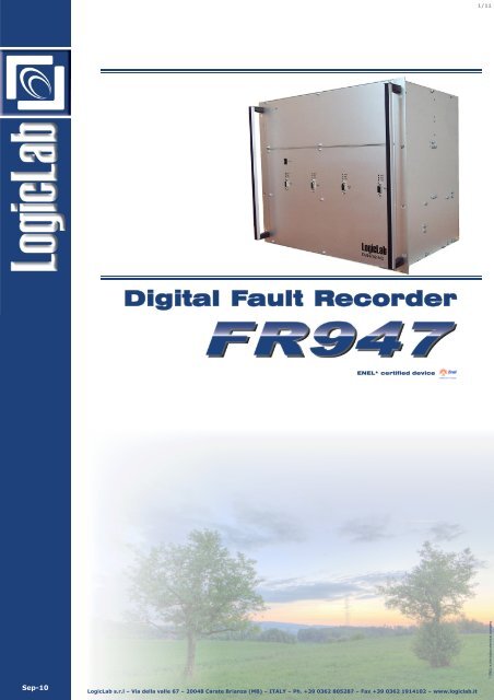
Sep-10<br />
<strong>Digital</strong> <strong>Fault</strong> <strong>Recorder</strong><br />
ENEL* certified device<br />
<strong>LogicLab</strong> s.r.l – Via della valle 67 – 20048 Carate Brianza (MB) – ITALY – Ph. +39 0362 805287 – Fax +39 0362 1914102 – www.logiclab.it<br />
1/11<br />
* ENEL is the italian electrical company
Foreword<br />
<strong>Digital</strong> <strong>Fault</strong> <strong>Recorder</strong> FR947<br />
High Performance fault and events recorder<br />
FR947 is a family of digital fault recorder. This is a flyer of base version of the DFR family,<br />
<strong>LogicLab</strong> portfolio is completed with EX version (Extended Signal Processor capability) and<br />
PMU version (Phasor Measurement Unit).<br />
<strong>LogicLab</strong> has developed a high-performance device, achieving a fault recorder that has no<br />
comparison with the other ones on the market.<br />
With up to 32 analog inputs (voltage and current) noise-free and 128 digital inputs, it provides<br />
great potential with high levels of precision and accuracy. Each channel (analog or<br />
digital) is isolated from all the other channels, power supply and ground.<br />
The device is intended for power distribution medium and high voltage substations, and it is<br />
used to record currents, voltages and digitals input following the occurrence of a trigger condition<br />
which can be set both as analog or digital inputs, as you please. User can set trigger<br />
on analog inputs using threshold (Max, Min or rate) on RMS value, fundamental RMS value,<br />
THD, positive sequence, negative sequence, zero sequence, active and reactive power, frequency.<br />
All trigger conditions (analog and digital) can be enabled and used in logical OR with<br />
other triggers or used in logical AND equations.<br />
<strong>Digital</strong> fault recorder FR947 uses the GPS signal for time synchronization and events timestamp.<br />
This feature provides a time value with resolution of ms and a µs accuracy. GPS receiver<br />
is integrated into the device and fault recorder is equipped with an external antenna.<br />
Other synchronization source, as NTP server or IRIG-B, are available.<br />
Equipped with an ethernet 10/100 BASE-TX (100 BASE-FX on demand) and RS232 connection,<br />
the user, with a common PC, can obtain a fully parameterization, remote control over<br />
VPN network, and remote recording download. FR947 is equipped with an internal flash<br />
memory and, with automatic download, the device memory capability to the computer mass<br />
storage device.<br />
FR947 is equipped with two user-friendly software:<br />
1) SpyFR947 for a complete device management, providing realtime tools, recording management<br />
and parameterization;<br />
2) LogOscillo: a complete set of tools for an effective, powerful and precise recording<br />
analysis.<br />
<strong>LogicLab</strong> can supply tailored multi-device system based customer specification with multidevice<br />
and high performance industrial PC, complete of rack and cabling on terminal block<br />
based on to meet large demands of analog and digital inputs.<br />
FR947 Power, precision and reliability.<br />
<strong>LogicLab</strong> s.r.l – Via della valle 67 – 20048 Carate Brianza (MB) – ITALY – Ph. +39 0362 805287 – Fax +39 0362 1914102 – www.logiclab.it<br />
2/11
Analog inputs<br />
FR947 is equipped with 32 analog inputs,<br />
with current/voltage partition in<br />
factory configurable in group of four (ex.<br />
16 current inputs and 16 voltage inputs).<br />
Each channel allows to acquire signals<br />
and perform many measures with bandwidth<br />
(-3 dB) DC ÷ 3.5 KHz and, thanks<br />
to the system architecture, ensure flat<br />
band (± 0.005 dB) between<br />
DC÷3.25KHz with an attenuation for frequencies<br />
greater than 3.5 KHz that exceeding<br />
100 dB. For all analog inputs, the<br />
sampling frequency is 7.2KHz.<br />
Each analog input is converted with high<br />
performance 24 bit ADC, to obtain a<br />
resolution of 16 bits without noise (noisefree).<br />
For each current input it is possible to<br />
measure up to 150Arms for one second<br />
without loss of accuracy, and up to 40Arms<br />
permanently with a resolution (worst<br />
case) that is better than 4.6 mArms. On<br />
client demand, <strong>LogicLab</strong> can supply devices<br />
with improved current capability up<br />
to 300Arms.<br />
For each voltage input it is possible to<br />
measure up to 700Vrms permanently with<br />
a resolution, in the worst case, that is<br />
better then 21mVrms. With this fault recorder<br />
it is possible to obtain excellent<br />
values of signal-noise ratio up to 92dB<br />
regardless of the used full-scale range.<br />
The user is able to set different full-scale<br />
range to obtain a better precision on<br />
small amplitude signals, both for voltage<br />
and current channels. This can be obtained<br />
through a software command that<br />
sets the system according to the user’s<br />
needs.<br />
The use of purely resistive sensor also<br />
ensures signals without delay, phase error<br />
and distortion.<br />
Each channel is fully isolated from all<br />
other inputs, power supply and ground<br />
(3000V DC).<br />
<strong>Digital</strong> inputs<br />
FR947 is equipped with 128 digital inputs<br />
that allow you to record events, alarms<br />
and commutations of signals with<br />
voltage from 18V to 150V.<br />
FR947 performs a scan of every digital<br />
input with a frequency of 1KHz.<br />
Each channel is isolated from all other<br />
inputs, power supply and ground (3000V<br />
DC).<br />
<strong>Digital</strong> <strong>Fault</strong> <strong>Recorder</strong> FR947<br />
Analog and digital acquisition unprecedented<br />
Recordings<br />
FR947-EX can perform two types of recordings:<br />
DFR - <strong>Digital</strong> <strong>Fault</strong> Recording<br />
All analog and digital inputs waveforms<br />
are recorded with programmable sample<br />
rate and stored in Compact Flash card<br />
memory. The recording is triggered by a<br />
minimum, maximum and rate (not available<br />
for all measures) condition on fundamental<br />
RMS value, RMS value, frequency,<br />
RMS value of the positive, negative and<br />
zero sequence, active power (P), reactive<br />
power (Q), THD or edge condition on<br />
digital input.<br />
CSR - Continuous Slow Recording<br />
With CSR user can store fundamental<br />
RMS value, RMS value, frequency, THD,<br />
RMS value of the positive, negative and<br />
zero sequence, apparent power (S), active<br />
power (P), reactive power (Q), cosφ,<br />
imbalance, with rate up to 100ms. The<br />
recording start after user software command,<br />
with a DFR recording, or with trigger<br />
based on programmed date and time.<br />
The recordings consists of three “times”<br />
with user configurable lengths : pre-fault<br />
time, fault time, post-fault time (only for<br />
DFR recordings).<br />
A single DFR recording length can reach<br />
150s. The maximum number of recording<br />
stored in flash memory is related to the<br />
recording time configuration. With automatic<br />
download to PC user can store<br />
many recording (with 16GB of available<br />
space on hard disk it is passible to store<br />
over 35.000s). In CSR mode the user can<br />
store measure only directly on PC.<br />
For all type of recording, using LogOscillo<br />
software, the user can perform multiple<br />
analysis.<br />
<strong>LogicLab</strong> s.r.l – Via della valle 67 – 20048 Carate Brianza (MB) – ITALY – Ph. +39 0362 805287 – Fax +39 0362 1914102 – www.logiclab.it<br />
3/11
Analog inputs examples<br />
150<br />
100<br />
50<br />
0<br />
-50<br />
-100<br />
-150<br />
150<br />
100<br />
50<br />
0<br />
-50<br />
-100<br />
-150<br />
150<br />
100<br />
50<br />
0<br />
-50<br />
-100<br />
-150<br />
0<br />
0<br />
-200<br />
0<br />
250<br />
200<br />
150<br />
100<br />
50<br />
0<br />
-50<br />
-100<br />
-150<br />
60<br />
40<br />
20<br />
0<br />
-20<br />
-40<br />
-60<br />
-80<br />
-100<br />
60<br />
40<br />
20<br />
0<br />
-20<br />
-40<br />
-60<br />
-80<br />
-100<br />
0<br />
0<br />
0<br />
10<br />
10<br />
10<br />
10<br />
10<br />
10<br />
V 5- Portata: 100V - mV<br />
20<br />
V 6- Portata: 200V - mV<br />
20<br />
V 7- Portata: 700V - mV<br />
20<br />
V 5- Portata: 100V - mV<br />
20<br />
I 1- Portata: 5A * 30 - mA<br />
20<br />
I 2- Portata: 1A * 30 - mA<br />
20<br />
<strong>Digital</strong> <strong>Fault</strong> <strong>Recorder</strong> FR947<br />
High accuracy noise-free analog inputs<br />
30<br />
30<br />
30<br />
30<br />
30<br />
30<br />
The chart on the left shows a voltage sinusoidal<br />
signal with amplitude 100mVrms<br />
(282mVpp) acquired by a voltage channel<br />
with 100Vrms (282Vpp) full-scale.<br />
<strong>LogicLab</strong> s.r.l – Via della valle 67 – 20048 Carate Brianza (MB) – ITALY – Ph. +39 0362 805287 – Fax +39 0362 1914102 – www.logiclab.it<br />
40<br />
40<br />
40<br />
40<br />
40<br />
40<br />
The chart on the left shows a voltage sinusoidal<br />
signal with amplitude 100mVrms<br />
(282mVpp) acquired by a 200Vrms (564Vpp)<br />
full-scale voltage channel.<br />
The chart on the left shows a voltage sinusoidal<br />
signal with amplitude 100mVrms<br />
(282mVpp) acquired by a 700Vrms (1974Vpp)<br />
full-scale voltage channel.<br />
You can see here that the channel is noise-free: the only<br />
noise being quantization (± ½ LSB), which is intrinsic in<br />
analog to digital conversions.<br />
LSB = 1974V/2 16 = 30mV<br />
Noise = ± 15mV<br />
4/11<br />
The chart on the left shows a square waveform<br />
with amplitude 100mVrms (282mVpp)<br />
acquired by a 100Vrms (282Vpp) full-scale<br />
voltage channel.<br />
The chart on the left shows a current sinusoidal<br />
signal with amplitude 50mArms (141<br />
mApp) acquired by a 150Arms (IMAX=424App)<br />
full-scale current channel.<br />
The chart on the left shows a current sinusoidal<br />
signal with amplitude 50mArms (141<br />
mApp) acquired by a 30Arms (IMAX=84App)<br />
full-scale current channel.
SpyFR947<br />
<strong>LogicLab</strong> PC software SpyFR947, is provided<br />
with FR947 to perform setting and<br />
analysis functions:<br />
��Communication settings;<br />
��Access with user name and password;<br />
��Analog inputs configuration;<br />
��<strong>Digital</strong> inputs configuration;<br />
��Device parameterization;<br />
��Real-Time visualization of digital inputs;<br />
��Real-Time visualization of analog waveform;<br />
��Real-Time spectrum analysis of analog<br />
input;<br />
��Real-Time measures;<br />
��Measure waveforms;<br />
��Manual trigger for DFR and CSR;<br />
��Events setup and analysis;<br />
��Self diagnostic;<br />
��Recordings management;<br />
��Off-line device configuration;<br />
��Firmware upload.<br />
Connection with the device can be done<br />
using RS232 or 10/100 Ethernet communication<br />
(UDP or TCP/IP). FR947 can configured<br />
as node on LAN/WAN network.<br />
All analog inputs can be configured with a<br />
label for easy identification, full-scale for<br />
best fit the input to the signal that will be<br />
acquired, transformer ratio for visualization<br />
with value reported to the primary<br />
values.<br />
All digital inputs can be configured with a<br />
label and acronym for easy identification,<br />
define a subsystem value to group different<br />
inputs and define if the inputs is active<br />
low or high.<br />
<strong>Digital</strong> <strong>Fault</strong> <strong>Recorder</strong> FR947<br />
SpyFR947: Local and remote management<br />
A powerful tool for recording management<br />
allow users to easy download, delete<br />
and search. Each recording is identified<br />
with an id, time and date of trigger,<br />
length, and trigger condition.<br />
SpyFR947 is supplied with many tools for<br />
real time analysis. User can see in real<br />
time the waveform of the analog signals<br />
acquired by the device or their spectrum<br />
analysis. All measures performed by the<br />
device can be visualized both with numerical<br />
mode than in graphic mode to<br />
evaluate trend and system behavior.<br />
FR947 is equipped with event recorder. It<br />
can be fully configured and a tool allow<br />
user to perform easy visualization, search<br />
and statistics.<br />
SpyFR947 allow user to perform manual<br />
trigger for DFR and CSR, force CPS synchronization,<br />
device reset, firmware upgrade,<br />
configuration file upload and<br />
download.<br />
On the lower side of the window, a status<br />
bar inform user about communication<br />
status, device and recording status, date<br />
and time with synchronization status.<br />
<strong>LogicLab</strong> s.r.l – Via della valle 67 – 20048 Carate Brianza (MB) – ITALY – Ph. +39 0362 805287 – Fax +39 0362 1914102 – www.logiclab.it<br />
5/11
<strong>Digital</strong> <strong>Fault</strong> <strong>Recorder</strong> FR947<br />
Exploring SpyFR947 in pictures<br />
The image shows a Real-Time window<br />
for analog input visualization<br />
through a remote connection access<br />
to FR947. This valuable tool allows<br />
users to show the input signals at<br />
any time.<br />
User can run the Real-Time spectrum<br />
analysis of an analog signal. With<br />
this tool, with many features, user<br />
can verify the presence of harmonics<br />
in real time.<br />
Real-Time measures window provides<br />
an indispensable tool for monitoring<br />
the substation.<br />
Real-Time digital inputs window provides<br />
a useful tool during maintenance.<br />
To help the operator, the window<br />
replies the physical layout of the<br />
device backside.<br />
This is the recordings management<br />
window. Each recording is identified<br />
by a number, date and time of fault<br />
event (ms accuracy), duration and<br />
trigger condition. The recording can<br />
be downloaded and deleted by selecting<br />
only the records of interest,<br />
or acting on all records in memory.<br />
With search tool, the user can easily<br />
find the recording of interest within<br />
all recordings saved.<br />
<strong>LogicLab</strong> s.r.l – Via della valle 67 – 20048 Carate Brianza (MB) – ITALY – Ph. +39 0362 805287 – Fax +39 0362 1914102 – www.logiclab.it<br />
6/11
LogOscillo<br />
<strong>Digital</strong> <strong>Fault</strong> <strong>Recorder</strong> FR947<br />
LogOscillo: the analysis software powerful and easy to use<br />
LogOscillo is the <strong>LogicLab</strong> software for<br />
DFR and CSR recording analysis. Software<br />
is supplied with the device and with<br />
SpyFR947.<br />
Each DFR recording collects all digital and<br />
analog inputs. User can choose which signal<br />
must be showed and the color of the<br />
related waveform.<br />
Some screens filter make this selection<br />
easy and immediate. User can choose<br />
only channels that meet certain conditions<br />
(signals above a threshold, current<br />
inputs , voltage inputs, etc.).<br />
On each analog signal user can perform<br />
many operations to get a deeper analysis<br />
of the waveform. Using the right mouse<br />
button, user can obtain RMS value, real<br />
RMS value, THD and spectral analysis.<br />
User can see the RMS value and fundamental<br />
RMS as a waveform overlapped to<br />
the signal selected.<br />
To help users in recording analysis, in addition<br />
to the features explained above,<br />
many tools are included in LogOscillo:<br />
��Recording explorer<br />
��Vertical and horizontal zoom;<br />
��Window zoom;<br />
��Waveform overlapping;<br />
��Time cursors;<br />
��Punctual amplitude and time value<br />
��Amplitude and time value at cursor position;<br />
��Zero crossing function;<br />
��Maximum and minimum search;<br />
��Decimation;<br />
��Phase analysis with symmetrical components<br />
��Waveform export (jpg, pdf, Comtrade);<br />
��Waveform printing.<br />
An helpful feature allow user to link different<br />
recordings in time. Software automatic<br />
adjust time axes for multiple analysis.<br />
Time cursor will be moved together<br />
over all recordings time linked. This feature<br />
helps users to make analysis of recordings<br />
downloaded from different device<br />
with occurrence of triggers at the<br />
same time that can be comparable.<br />
This feature permits to <strong>LogicLab</strong> to supply<br />
complex system with multi device to satisfy<br />
customers with high demands of analog<br />
and digital inputs. Each FR947 can be<br />
configured to send an ethernet message<br />
for triggering another devices.<br />
In the same way, this feature allow users<br />
to perform analysis in distributed system<br />
equipped with <strong>LogicLab</strong> devices.<br />
<strong>LogicLab</strong> s.r.l – Via della valle 67 – 20048 Carate Brianza (MB) – ITALY – Ph. +39 0362 805287 – Fax +39 0362 1914102 – www.logiclab.it<br />
7/11
Communication<br />
FR947 is designed to interface with modern<br />
communication technologies and it<br />
meet all the requirements for monitoring<br />
and remote management.<br />
With a front serial port, ethernet port and<br />
a rear serial port used for communication,<br />
FR947 can be connected locally or<br />
remotely. The communication ports, both<br />
front serial and ethernet, are isolated<br />
(Ethernet: 1500Vrms - RS232:<br />
2500Vrms), ideal for applications with<br />
high safety standards. The rear serial<br />
port provide hardware flow control for<br />
modem communication.<br />
Through the rear serial port is possible to<br />
connect an analog dial-up modem or GSM<br />
modem, which allows remote connection.<br />
Ethernet 10/100BASE-TX compliant to<br />
IEEE 802.3 port is available on front.<br />
With cross-over cable, user can establish<br />
an ethernet direct connection to FR947<br />
with a PC without using additional network<br />
device (Hub or switch).<br />
On client demand, FR947 can be<br />
equipped with an optional board that integrate<br />
multiple ethernet port with<br />
100BASE-FX (fiber optic) capability.<br />
FR947 can be configured as a node of a<br />
LAN/WAN network using TCP-IP or UDP<br />
transmission protocols. Once assigned<br />
the IP address and networked, any PC on<br />
the LAN can access the device using<br />
SpyFR947. The Ethernet port can be used<br />
to connect an ADSL modem or a satellite<br />
modem where standard connections are<br />
not available. Through these communication<br />
means, user can establish a remote<br />
connection quickly. It is also possible to<br />
create a VPN (Virtual Private Network).<br />
<strong>Digital</strong> <strong>Fault</strong> <strong>Recorder</strong> FR947<br />
All local and remote connections that you need<br />
With the VPN, remote device will be seen<br />
as directly connected to the LAN network.<br />
For the operator working in the control<br />
center, FR947-EX will be appear as on his<br />
desktop and use the remote device as if it<br />
were local.<br />
The connection allows user to remotely<br />
make any operation without limitation<br />
with all RealTime analysis tools that are<br />
available on SpyFR947. In addition, with<br />
the automatic download feature, user can<br />
use a common remote PC for storage<br />
data information.<br />
By any communication ports, the connection<br />
with FR947-EX is always direct and<br />
automatic with no need for intermediate<br />
devices such as PCs or industrial units.<br />
<strong>LogicLab</strong> s.r.l – Via della valle 67 – 20048 Carate Brianza (MB) – ITALY – Ph. +39 0362 805287 – Fax +39 0362 1914102 – www.logiclab.it<br />
8/11
Hardware Technical data<br />
<strong>Digital</strong> <strong>Fault</strong> <strong>Recorder</strong> FR947<br />
Power, accuracy and reliability at an affordable price<br />
Power supply<br />
Power supply voltage: 110V DC ± 20%<br />
Nominal power: 40W<br />
AC version available on client demand<br />
Different power supply voltage available on client demand<br />
Dimensions and environmental specification<br />
Height / Width / Depth: up to 9U / 19” / 31cm<br />
Temperature range: -10 ÷ 55 ºC<br />
Temperature range (Absolute maximum rating): -15 ÷ 70 ºC<br />
Storage temperature: -40 ÷ 85 ºC<br />
Relative Humidity: � 95 %<br />
Atmospheric pressure: 70 ÷ 106 kPa<br />
Analog inputs noise-free isolated input<br />
Dielectric strength: 3000V DC (1 min - 100% tested)<br />
Sample rate: 14,4 KHz<br />
Bandwidth (-3 dB): DC (0 Hz) ÷ 3,5 KHz<br />
Flat bandwidth(±0,005 dB): DC (0 Hz) ÷ 3,25 KHz<br />
Stop band attenuation: >100 dB<br />
Different configuration of current/voltage analog input<br />
Available options: 32V, 28V+4I, 24V+8I, 20V+12I, 16V+16I,<br />
12V+20I, 8V+24I, 4V+28I, 32I<br />
Under-equipped configuration for cost-saving solution<br />
Current analog inputs<br />
Rated current (In): 1Arms / 5Arms<br />
Full-scale range: 50 Arms / 150 Arms / 300 Arms<br />
Accuracy guaranteed range: 0,01·In ÷ 30·In<br />
Rated current setup by software command<br />
Accuracy:
<strong>Digital</strong> <strong>Fault</strong> <strong>Recorder</strong> FR947<br />
Power, accuracy and reliability at an affordable price<br />
Recording and Software Technical data<br />
<strong>Fault</strong> Recording (DFR)<br />
Recording on removable integrated flash memory<br />
Automatic download to Personal Computer<br />
Flash memory space available up to 250s recordings.<br />
Three timer user selectable<br />
Pre-trigger time: 50 ms ÷ 5 s (10s on client demand)<br />
<strong>Fault</strong> time: 100 ms ÷ 60 s<br />
Post fault time: 50 ms ÷ 5 s<br />
Retriggering during recording time available<br />
Recording timeout (max): 150 s<br />
Trigger on analog threshold of (max, min, rate)<br />
RMS (max, min, rate)<br />
Fundamental RMS (max, min,rate)<br />
Positive, negative and zero sequence (I1,2,0,U1,2,0)(max, min)<br />
Power and energy: P, Q (max, min)<br />
Frequency (max, min, rate)<br />
THD (max)<br />
Trigger on digital edge (falling, rising, both)<br />
Software trigger<br />
Events timestamp<br />
Data saved (data packet):<br />
(IL,N,UL,N) samples of all 32 channels inputs<br />
<strong>Digital</strong> input state of all 128 channel inputs<br />
Continuous Slow Recording (CFR)<br />
Recording on Personal Computer<br />
Data pack rate: 100 ms ÷ 10 s<br />
Trigger for continuous slow recording<br />
With DFR recording trigger<br />
Software (start and stop)<br />
Scheduled data and time (start and stop)<br />
For trigger with DFR recording two timer user selectable<br />
Pre-trigger time: 0 s ÷ 3600 s<br />
<strong>Fault</strong> time: 1 s ÷ 3600 s<br />
Data saved (data packet):<br />
RMS of all 32 channels inputs<br />
Fundamental RMS of all 32 channels inputs<br />
THD of all 32 channels inputs<br />
Frequency<br />
Power (S, P e Q)<br />
cosφ<br />
Positive, negative and zero sequence (I1,2,0,U1,2,0)<br />
Imbalance<br />
Sequence event recording (SER)<br />
128 <strong>Digital</strong> inputs event source<br />
Time resolution: 1ms<br />
Time precision: 1µs<br />
200.000 events buffer on solid state disk<br />
Enable on each input<br />
Input description label<br />
Programmable Off State description label<br />
Programmable On State description label<br />
<strong>LogicLab</strong> s.r.l – Via della valle 67 – 20048 Carate Brianza (MB) – ITALY – Ph. +39 0362 805287 – Fax +39 0362 1914102 – www.logiclab.it<br />
10/11<br />
Parameterization and device management software<br />
SpyFR947<br />
Communication interface selection (RS232, UDP, TCP, modem setup)<br />
Access with user name and password<br />
Define up to 20 different users<br />
Five security level access (Administrator, Expert user, Base user, restricted<br />
access, Guest)<br />
Software access configuration and folder management<br />
Analog inputs insertion definition<br />
Analog inputs setup (label, full-scale, transformer ratio)<br />
<strong>Digital</strong> inputs setup (label, acronym, active low/high)<br />
Events setup (id, enable, enable store/send/print/, state labels)<br />
Analog trigger setup (max, min, rate on RMS, fundamental RMS and max<br />
THD)<br />
Calculated trigger setup (max, min on positive, negative and zero sequence,<br />
active and reactive power, frequency)<br />
<strong>Digital</strong> trigger setup (falling, rising and both edge)<br />
Equation trigger setup<br />
Device labelling<br />
Time zone correction<br />
Full TCP/IP Ethernet configuration parameters<br />
Backside RS232 throughput configuration<br />
Event parameterization<br />
<strong>Fault</strong> recording monitor (enabling, recording status, memory available)<br />
Recording time setup (Pre-trigger time, fault time, post-fault time)<br />
Memory configuration setup (circular buffer or full-fill buffer)<br />
Recording extension setup (disable, on fault time, on post-fault time)<br />
Self-diagnostic device state<br />
Remote reset device<br />
DFR recording trigger<br />
CSR recording trigger wizard<br />
Force GPS synchronization<br />
Analog waveform real-time view tool<br />
Spectrum real-time analysis tool<br />
Analog measure real-time view tool (Frequency; RMS; Fundamental RMS;<br />
THD; positive, negative and zero sequences; Power P, Q, S; Cosφ)<br />
Analog measure waveform real-time view tool<br />
Waveform and measure can be reported to primary side of transformers<br />
<strong>Digital</strong> inputs real-time view tool<br />
Firmware update wizard<br />
Recordings management with search and statistics tool<br />
Events management with search and statistics tool<br />
Device parameterization file management tools (off-line editing, download<br />
file, upload file)<br />
Status bar with connection status, time and data, GPS link, device status,<br />
recording and event status, communication activity.<br />
Recordings analysis software<br />
LogOscillo<br />
Waveform selection wizard with colours assignment<br />
Automatic selection filters for analog and digital inputs<br />
Decimation value for waveform preview<br />
Auto-decimation for best performance/details ratio<br />
Absolute and complete date/time visualization on time axes<br />
Recording explorer with summary display for each recording<br />
Double time cursor<br />
Time and amplitude value in time cursor position with time interval<br />
Time and amplitude value in mouse cursor position<br />
Window zoom tool (zoom between cursor)<br />
Horizontal and Vertical zoom tool<br />
Drag-and-Drop capability for waveform overlapping<br />
Restore default visualization<br />
Zero crossing search tool<br />
Max/Min search tool<br />
Amplitude normalization for graphical comparison<br />
Signal processing for RMS waveform visualization<br />
Signal processing for fundamental RMS waveform visualization<br />
Signal processing for THD waveform visualization<br />
Signal processing for spectrum visualization<br />
Spectrum analysis with THD<br />
Phase analysis with vector representation of three phase system complete<br />
with symmetrical components<br />
Waveform export tool for image (JPG, BMP, MetaFile, PCX, PostScript, SVG)<br />
Waveform export tool for Acrobat Reader (pdf)<br />
Samples waveform export tool for Excel<br />
ComTrade waveform import/export (ASCII/Binary, rel. 1.0 or 2.0)<br />
Waveform print management<br />
Time link capability, useful for simultaneous time analysis with different<br />
recording
<strong>LogicLab</strong> S.r.l.<br />
Via della valle 67<br />
20048 Carate Brianza (MB) - ITALY<br />
Ph. +39 0362 80 52 87<br />
Fax +39 0362 19 14 102<br />
www.logiclab.it<br />
info@logiclab.it<br />
THE INFORMATION PROVIDED AT THIS CATALOG IS PROVIDED "AS IS" WITHOUT WARRANTIES OF ANY KIND, EXPRESS OR IMPLIED.<br />
<strong>LogicLab</strong> further does not warrant the accuracy, reliability or completeness of the information at this catalog. Use of any information is at your<br />
own risk. <strong>LogicLab</strong> may make changes to the information provided at this catalog, at any time without notice. The information provided at this<br />
catalog may be out of date, or contain errors and <strong>LogicLab</strong> makes no commitment to update or correct the materials at this catalog.<br />
11/11