Models ER10 & 10H Totalizers IOM - Badger Meter, Inc.
Models ER10 & 10H Totalizers IOM - Badger Meter, Inc.
Models ER10 & 10H Totalizers IOM - Badger Meter, Inc.

You also want an ePaper? Increase the reach of your titles
YUMPU automatically turns print PDFs into web optimized ePapers that Google loves.
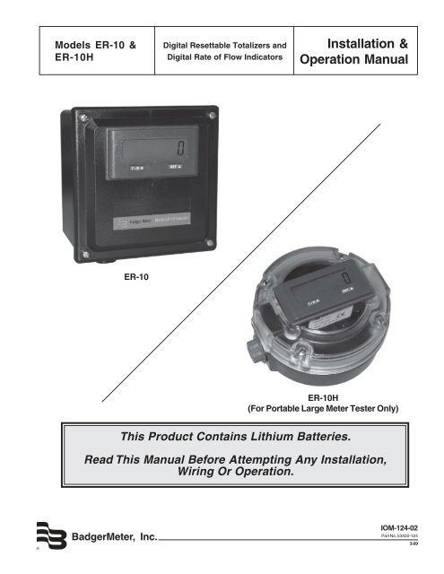
<strong>Models</strong> ER-10 &<br />
ER-<strong>10H</strong><br />
ER-10<br />
<strong>Badger</strong><strong>Meter</strong>, <strong>Inc</strong>.<br />
Digital Resettable <strong>Totalizers</strong> and<br />
Digital Rate of Flow Indicators<br />
This Product Contains Lithium Batteries.<br />
Installation &<br />
Operation Manual<br />
ER-<strong>10H</strong><br />
(For Portable Large <strong>Meter</strong> Tester Only)<br />
Read This Manual Before Attempting Any Installation,<br />
Wiring Or Operation.<br />
<strong>IOM</strong>-124-02<br />
Part No. 53400-124<br />
3-09
Scope of this manual<br />
This manual contains information concerning the installation,<br />
operation and maintenance of the <strong>Badger</strong> ® ER-10 and ER-<br />
<strong>10H</strong> electronic registers. To ensure proper performance, the<br />
instructions given in this manual should be thoroughly<br />
understood. Retain the manual in a readily accessible location<br />
for future reference.<br />
Installation, wiring and programming of either unit is fairly<br />
simple and straight forward. This manual is designed so as to<br />
provide you with a step by step guide for this purpose.<br />
General Information<br />
The ER-10 and ER-<strong>10H</strong> are external or battery powered<br />
electronic registers that display rate of flow and total flow.<br />
They have independent programmable scale factors for<br />
rate and totalization, allowing you to program these displayed<br />
values in different but meaningful engineering<br />
units, such as gallons per minute and total gallons.<br />
The LCD display with 8 digits for total, and 4 digits plus<br />
legend for rate, provides easy viewing at a glance. For<br />
conditions where ambient light is poor, the display can be<br />
Specifications<br />
POWER<br />
Internal Battery: 3V, Lithium<br />
Battery Life Expectancy: 5 years<br />
Replacement Part #: 65765-001<br />
External DC Power Source(10-30VDC)<br />
Max Current Draw = 30mA<br />
BACKLIGHT<br />
Requires 10-30VDC power input (max. current<br />
draw= 30mA)<br />
(Derate operating temperature 1°C/Volt<br />
above 17VDC)<br />
Reverse polarity protected<br />
PHYSICAL<br />
Operating Temperatures:<br />
32°F (0°C) to 130°F (55°C)<br />
Storage Temperature:<br />
-4°F (-20°C) to 160°F (70°C)<br />
Operating Humidity: 60% Non-condensing<br />
Weight: 2.2 oz. net<br />
Display Size: .43" high<br />
Front Panel Rating: NEMA 4X when mounted<br />
with gasket provided<br />
Case Material: Cycolac X-17<br />
TOTALIZER<br />
Digits: 8<br />
Scaler: 0.0001 - 99.999<br />
Decimal Point: 5 positions, programmable<br />
2<br />
Examples are provided only to facilitate programming.<br />
Your specific application will most likely require a different<br />
set of numbers for proper programming.<br />
The troubleshooting section attempts to illustrate the<br />
most common problems that can be encountered, their<br />
most likely cause and the recommended solution. If a<br />
problem persists, please contact our technical support<br />
group at:<br />
<strong>Badger</strong> <strong>Meter</strong>, <strong>Inc</strong>.<br />
Technical Support<br />
1-800-456-5023<br />
backlit by connecting an external DC (10-30 VDC) power<br />
supply. A single unit can accept NPN or dry contact inputs<br />
for low or high speed applications.<br />
The ER-10 and ER-<strong>10H</strong> models are powered by one 3V<br />
Lithium battery.<br />
Setup on either model is quick and easy as the two front<br />
panel keys are used to scroll through and preset values<br />
in all program mode choices.<br />
RATE INDICATOR<br />
Digits: 4/5, (4 calculated, 5 displayed with<br />
fixed 0 in LSD)<br />
Scaler Range: .001to 9999<br />
Decimal Point: 5 positions, programmable<br />
Accuracy: +/-0.2%<br />
Update Time: .7 seconds<br />
Zero Time: 10 seconds<br />
DC COMMON (Terminal 1)<br />
COUNT INPUT (Terminal 2)<br />
Speed: 0 to 100 hz<br />
Min. Low Time: 3.3 mS<br />
Min. High Time: 6.7 mS<br />
Impedance: 101K ohm<br />
Voltage Thresholds: Low: 0 to 0.4 VDC<br />
High: 2.0 to 28 VDC<br />
Max: High 28 VDC<br />
RESET INPUT (Terminal 4)<br />
Resets totalizer to zero when connected to DC<br />
common.<br />
Min. Low Time: 0.25 to 1.0 sec. (maintained)<br />
The required pulse width varies with count<br />
speed, scale factor and number of digits<br />
displayed.<br />
Voltage Thresholds: Low: 0 to 0.4 VDC<br />
High: 2.0 to 28 VDC<br />
PROGRAM ENABLE INPUT (Terminal 5)<br />
Operation: Level sensitive (maintained)<br />
COUNT ACCURACY<br />
100% when operated within specifications
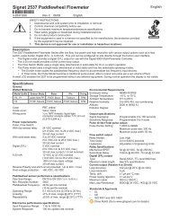
Installation<br />
Plastic<br />
front panel<br />
sealed to<br />
meet<br />
NEMA 4X<br />
Mode select/<br />
Programming<br />
button<br />
Panel Installation<br />
Slide the included gasket over the rear of the unit. Place the unit in the panel through a 33mm x 68mm cutout. Use the<br />
provided panel mount screws to tighten the mounting clips until there is a secure seal against the gasket. Do not over tighten.<br />
Slide the mounting clips into the grooves in the side of the <strong>ER10</strong>.<br />
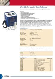
Wiring Instructions<br />
Terminal<br />
1<br />
2<br />
3<br />
4<br />
5<br />
6<br />
7<br />
Function<br />
Ground<br />
Input B<br />
Count Input<br />
Reset<br />
Program<br />
Enable<br />
Backlight<br />
Common<br />
Backlight<br />
Power<br />
Operation<br />
T / R<br />
2.677" (68mm)<br />
Recommended<br />
Panel Cutout<br />
FRONT VIEW<br />
Count Input<br />
Contact Closure or NPN 100 Hz. Max.<br />
Not Used<br />
TRANSMITTER CONNECTIONS<br />
For connecting to <strong>Badger</strong> <strong>Meter</strong> transmitters, refer to the<br />
Industrial Technical Brief (ITB) for your specific transmitter,<br />
and the chart to the right. "Connections" refers to the wires<br />
on the transmitter. The numbers in parenthesis refer to the<br />
terminal numbers on the ER-10. Connect the wire coming<br />
from the transmitter to the corresponding terminal number<br />
for the ER Remote models.<br />
To connect a generic reed switch to the ER-10, connect<br />
one of the wires to terminal 1. Connect the remaining wire<br />
to terminal 2.<br />
To connect a generic NPN transmitter to the ER-10, connect<br />
the emitter to terminal 1. Connect the collector to terminal<br />
2.<br />
RST<br />
Connect to Ground to Reset<br />
Totalizer. This is a maintained or<br />
Level Sensitive Reset.<br />
Connect to Ground to Enter<br />
Program Mode<br />
Connect to Power to Light Display<br />
®<br />
1.299"<br />
(33mm)<br />
8-digit LCD<br />
Display<br />
Reset/<br />
Programming<br />
button<br />
3<br />
Program enable<br />
Gasket Installed<br />
Install mounting clip<br />
5 Enable/R<br />
5 Enable/R<br />
REAR VIEW<br />
7 +10-30VDC<br />
6 DC Common<br />
Transmitter Connections<br />
FT1 (1/2" OP) Black (1) Black (2)<br />
FT1 White (1) White (2)<br />
FT2 White (1) White (2)<br />
FT420 Pulse Output Pulse Output<br />
Terminal – (1) Terminal + (2)<br />
MSE1 Black (1) Red (2)<br />
MSE5 Black (1) Red (2)<br />
PFT2 White (1) White (2)<br />
PFT3 White (1) White (2)<br />
PFT420 Pulse Output Pulse Output<br />
Terminal – (1) Terminal + (2)<br />
PFT420/2 Pulse Output Pulse Output<br />
Terminal – (1) Terminal + (2)<br />
PM5 Black (1) Red (2)<br />
Duran t<br />
RST 4<br />
IN B 2<br />
GND 1<br />
Reset<br />
Count Input<br />
Ground
Operation<br />
By pressing the key during normal operation, the ER-10 will alternatively display the Flow Total or the<br />
Flow Rate. The Letter R on the left indicates that the Flow Rate is being displayed.<br />
Total Display: Indicates the present<br />
count value, which is equal to the<br />
number of pulses received (since<br />
the last reset) multiplied by the Totalizer<br />
Scaler Value in Program mode<br />
#1.<br />
Rate Display: Indicates the rate<br />
value, which is equal to the input<br />
frequency multiplied by the Rate<br />
Prescale Value in Program Mode<br />
#3. (If no pulses are received for 2<br />
seconds, the rate value goes to<br />
zero.)<br />
Programming<br />
4<br />
Reset Key:<br />
If the total value is being displayed, depressing<br />
this key will cause the value to<br />
be reset to 0 as long as program mode #7<br />
is preset accordingly.<br />
or<br />
When the program input is active (see<br />
wiring) this key is used to select a menu<br />
item for editing.<br />
Down Key: Toggles the unit between the total and rate display. When the program input is<br />
active this key is used to scroll through the menu items. After a menu item has been chosen<br />
for editing, the down key is used to set the value for the currently selected (flashing) digit.<br />
Mode #1: Is used to enter the count<br />
scale factor. The far right digit will be<br />
flashing. Press the key until 1 01.0000<br />
reaching the desired digit value.<br />
NOTE: pressing and holding the<br />
key will cause the numbers<br />
to autoscroll. Next press the key to move the flashing digit<br />
one place to the left. Change this digit to the desired value with<br />
the key. Repeat this process until all digits are set<br />
correctly. (Setting the count scale factor to 00.0000 will allow<br />
scaling by 100 in ER Series.)<br />
Mode #2: Is used to enter the<br />
decimal point display on the totalizer<br />
screen. Press and hold the<br />
key and then press the key to<br />
move from screen one to screen<br />
two. Press the key to move<br />
the decimal point to the desired position.<br />
Mode #3: Allows the user to enter<br />
the rate scale factor. The lower case<br />
"d" appears on the right of the<br />
display when it is time to enter the<br />
decimal point position for the rate<br />
scaler. NOTE: This decimal point is<br />
3 0000<br />
used for the rate scaler only and will not appear on the ratemeter<br />
screen. Press the key to chance the first digit to the<br />
correct value. Press the key to select the next digit to be<br />
changed. Repeat this process untill all the digits are correct.<br />
When the 'd' appears, press the<br />
point is in the desired location.<br />
key until the decimal<br />
34675890<br />
R<br />
To enter the program mode, a connection must be made between<br />
terminals 1 and 5.<br />
Programming Screens<br />
Press and hold the key while repeatedly pressing the key<br />
to advance to successive screens.<br />
2 000000<br />
2345<br />
Programming Screens<br />
Screen<br />
Function<br />
1 Totalizer Scale Factor<br />
2 Totalizer Decimal Point<br />
3 Rate Scale Factor<br />
4 Rate Scale Factor Decimal Point<br />
5 Rate x1/x10<br />
6 Reset Key Enable/Disable<br />
Mode #4: Is used to enter the<br />
decimal point position for the<br />
ratemeter run-mode display. The<br />
display will show the screen number<br />
(4) and four zero's. Press the<br />
keyuntil the decimal point is in the<br />
correct position.<br />
4 0000<br />
Mode #5: Is used to select the rate<br />
display multiplier of one or ten.<br />
Selecting rate x10 will add a zero to 5 1<br />
the far right of the display. This zero<br />
will not change value and does not<br />
affect the decimal point. The display<br />
will show the screen number (5) and a 1 at the right. Press the<br />
keyto select 1 or 10.<br />
Mode #6: Is used to determine<br />
whether the front panel reset key will<br />
function. The screen will show a 6 r<br />
number 6 on the left and an R on the<br />
right. Press the key to<br />
choose the option you want.<br />
(R - Reset, NoR - Non-Reset) NOTE: The reset terminal on the<br />
rear panel is still active when the front reset button is disabled. To<br />
exit the program mode, break the connection between terminals 1<br />
and 5.
ER-10/ER-<strong>10H</strong> Programming Calculations<br />
TOTALIZER PROGRAMMING<br />
Totalizer values can be expressed in any engineering unit<br />
of measure such as gallons, quarts, liters, etc. For each<br />
unit a unique scale factor must be programmed.<br />
To determine the Totalizer Scale Factor (Program Mode<br />
#1), use the following formula:<br />
Totalizer Scale Factor =<br />
1/(Transmitter pulses per unit X Decimal Factor)<br />
where:<br />
Transmitter Pulses per Unit is the number from the chart<br />
at the right, or the Industrial Tech Brief (ITB) for your<br />
particular transmitter/meter combination. The chart is<br />
expressed in gallons and liters. If you wish to read in<br />
other units, use the appropriate conversion factor.<br />
Decimal Factor (from 1.0 to .001) determines the<br />
resolution of the reading. If you wish to read to the<br />
nearest 1/10 unit, the Decimal Factor would be 0.1.<br />
Example: You have a model 35 RCDL meter with a PFT2<br />
transmitter that has a pulse output of 126.7 pulses per<br />
gallon. You wish to read the totalizer to the nearest tenth<br />
gallon.<br />
1/(126.7 X 0.1) = 0.0789 (scale factor)<br />
Step #1: Set the Totalizer Scale Factor to 00.0789.<br />
(Program Mode #1)<br />
Step #2: Set the totalizer Decimal Point Factor to<br />
“00000.0” (one decimal place) (Program Mode #2).<br />
RATE OF FLOW PROGRAMMING<br />
Rate of flow can be expressed in any engineering unit of<br />
measure for any time base such as gallons/minute, liters/<br />
second, barrels/hour, etc.<br />
To determine the Rate Scale Factor (Program Mode #3),<br />
use the following formula:<br />
Rate Scale Factor =<br />
(Seconds / Transmitter Pulses per Unit X Decimal Factor)<br />
where:<br />
Seconds is the number of seconds in the rate time unit. If<br />
you wish to read flow in units per minute, seconds would<br />
equal 60. If you wish to read flow in units per hour,<br />
seconds would equal 3600.<br />
Transmitter Pulses per Unit is the number from the chart<br />
to the right or the Industrial Tech Brief (ITB) for your<br />
particular transmitter/meter combination. The chart is<br />
expressed in gallons and liters. If you wish to read in<br />
other units, use the appropriate conversion factor.<br />
Decimal Factor (from 1.0 to 0.001) determines the<br />
resolution of the reading. If you wish to read the rate to the<br />
rearest 1/10 unit, the Decimal Factor should be 0.1.<br />
5<br />
Before you program the Rate Scale Factor, you must set<br />
the Rate Decimal Point position (Program Mode #4). This<br />
decimal point will correspond to the decimal in the Rate<br />
Scale Factor number.<br />
Example: You have a model 35 RCDL meter with a PFT2<br />
transmitter that has a pulse output of 126.7 pulses per<br />
gallon. You wish to read rate of flow in gallons per minute.<br />
(60 seconds /126.7 pulses per gallon X 1.0<br />
= 60/126.7 = 0.473(rate scale factor)<br />
Step #1: Set the rate scale factor to 0.473 (Program mode<br />
# 3).<br />
Step #2: Since we are reading in whole gallons, set<br />
program mode #4 (Rate Decimal Point) to 0000.<br />
Step #3: Since we are reading in whole gallons (no<br />
multiplier), set program mode #5 to 1.<br />
Size<br />
Transmitter Pulses<br />
per Unit chart<br />
FT1 FT2<br />
PFT2 PFT3<br />
PFT2E FT1E<br />
FT420 PFT420<br />
(<strong>Inc</strong>hes) <strong>Meter</strong> Model Gallons Liters<br />
1/2 OP 223.0 58.9<br />
1/2 OP(FT1 only) 111.5 29.4<br />
1 OP 76.6 20.2<br />
2 OP 20.6 5.4<br />
2 IND'L TURBO * 17.36 * 4.6<br />
3 IND'L TURBO * 12.4 * 3.2<br />
4 IND'L TURBO * 2.56 * 0.6<br />
6 IND'L TURBO * 1.08 * 0.2<br />
5/8 25 IND RCDL 198.4 52.4<br />
3/4 35 IND RCDL 126.7 33.5<br />
1 40 IND RCDL 89.8 23.7<br />
1 70 IND RCDL 46.8 12.4<br />
1 1/2 120 IND RCDL 23.8 6.3<br />
2 170 IND RCDL 14.6 3.9<br />
3 TSM METER 1.598 0.422<br />
*If using a PFT3E transmitter, multiply number by 2.
Troubleshooting<br />
PROBLEM POSSIBLE CAUSES REMEDIES<br />
Screen is blank 1. Battery is dead. 1. Replace battery.<br />
Will not count in totalizer mode 1. Improperly programmed. 1. Check programming.<br />
2. Broken or defective wiring. 2. Check wiring.<br />
3. Improperly connected. 3. Check connections.<br />
4. Transmitter defective. 4. Repair or replace transmitter.<br />
Will not indicate rate of flow 1. Improperly programmed. 1. Check programming.<br />
2. Improperly connected. 2. Check connections.<br />
3. Transmitter defective. 3. Repair or replace transmitter.<br />
Cannot program 1. Program enable jumper is not 1. Install jumper from Terminal #1<br />
installed or installed improperly. to #5.<br />
Cannot reset from front panel 1. Reset enable is not<br />
programmed.<br />
1. Reprogram mode #6 to "R."<br />
Erroneous readings 1. Improperly programmed. 1. Check programming.<br />
2. Defective transmitter. 2. Repair or replace transmitter.<br />
Field Calibration<br />
Field calibration consists of determining the exact transmitter<br />
pulse output per unit of measure for your particular meter/<br />
transmitter combination and then using this value as the<br />
transmitter pulse output value when calculating the counter<br />
and time base values on page 4.<br />
The procedure is as follows:<br />
1. Set the totalizer scale factor to 01.0000. (MODE #1)<br />
2. Set the totalizer Decimal Point to 000000. (MODE #2)<br />
3. Reset the counter to “zero”.<br />
For further assistance, call our Technical Support Staff at 1-877-243-1010.<br />
4. Run fluid into a weigh tank or calibrated vessel.<br />
5. Determine number of pulses per gallon by dividing indicator<br />
reading by number of gallons of fluid in the vessel. Use<br />
this value for your calculations.<br />
6<br />
Example:<br />
You programmed the indicator for calibration and connected<br />
the outlet of a 1" OP meter to a calibrated vessel. You opened<br />
the valve and allowed fluid to flow into the vessel. You<br />
determined that there was 22.35 gallons of fluid in the vessel.<br />
The reading on the indicator is 1720.<br />
1720 / 22.35 = 76.95<br />
The transmitter output is 76.95 pulses per gallon. Use 76.95<br />
when calculating the Totalizer Scale Factor on page 5.
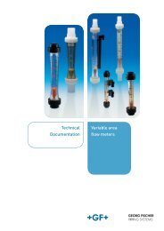
METER MOUNT SURFACING<br />
(ER-10)<br />
If replacement of your sensor pickup on your meter is<br />
required, please follow the following steps:<br />
INDUSTRIAL TURBO METER<br />
1. Remove the front cover on the ER-10 unit and<br />
disconnect all wiring.<br />
2. Remove meter head bolts and lift meter head<br />
assembly from housing.<br />
3. Remove retaining ring which retains the accessory<br />
unit to the head.<br />
4. Loosen the side seal screw on the accessory<br />
adapter, twist 90 degrees and pull entire assembly<br />
unit from the meter head.<br />
5. Twist drop pipe in counterclockwise direction to<br />
remove it and the ER-10 unit from the adapter<br />
assembly.<br />
6. Obtain new adapter assembly and reassemble to<br />
drop pipe and ER-10 unit.<br />
7. Reverse the balance of the above steps.<br />
DISC METER<br />
1. Remove the front cover on the ER-10 unit and<br />
disconnect sensor wiring.<br />
2. Loosen the side seal screw on the assembly<br />
adapter, twist 90 degrees and lift entire accessory<br />
unit off bare meter.<br />
OP INDUSTRIAL<br />
TURBO<br />
7<br />
DISC<br />
3. Pull the reed switch pickup assembly and pad from<br />
adapter.<br />
4. Replace pickup and pad in adapter, feeding wires up<br />
through the drop pipe.<br />
5. Reposition entire assembly on meter.<br />
6. Rewire sensor to ER-10 unit.<br />
OP METER<br />
1. Remove the front cover on the ER-10 unit and<br />
disconnect sensor wiring.<br />
2. Remove the back plate on the meter to expose the<br />
pickup assembly.<br />
3. Remove the reed switch pickup assembly and<br />
replace.<br />
4. Feed wires up through the drop pipe.<br />
5. Reassembly the back plate in position.<br />
6. Rewire sensor wires to ER-10 unit.
<strong>Badger</strong> ® is a registered trademark of <strong>Badger</strong> <strong>Meter</strong>, <strong>Inc</strong>.<br />
Copyright © <strong>Badger</strong> <strong>Meter</strong>, <strong>Inc</strong>. 2009. All rights reserved.<br />
Please see our website at<br />
www.badgermeter.com<br />
for specific contacts.<br />
Due to continuous research, product improvements and enhancements,<br />
<strong>Badger</strong> <strong>Meter</strong> reserves the right to change product or system specifications<br />
without notice, except to the extent an outstanding contractual obligation exists.<br />
®<br />
<strong>Badger</strong><strong>Meter</strong>, <strong>Inc</strong>.<br />
P.O. Box 245036, Milwaukee, WI 53224-9536<br />
Telephone: (414) 355-0400 / (800) 243-1010<br />
Fax: (414) 355-7499 / (866) 613-9305<br />
www.badgermeter.com