Organic scintillator
Organic scintillator
Organic scintillator

Create successful ePaper yourself
Turn your PDF publications into a flip-book with our unique Google optimized e-Paper software.
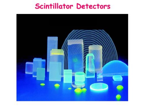
Scintillator Detectors
Electrons formed in ionization process<br />
are NOT the same giving the electronic signals !!!
= phosphorescence<br />
Light is produced by<br />
deexcitations of<br />
molecules<br />
Phosphorescence is a property of<br />
many crystals and organic materials
ZnS: the precursor of modern <strong>scintillator</strong> counters<br />
In 1903 W. Crookes demonstrated in England his<br />
“spinthariscope” for the visual observation of individual<br />
scintillations caused by alpha particles impinging upon a ZnS<br />
screen. In contrast to the analogue methods of radiation<br />
measurements in that time the spinthariscope was a singleparticle<br />
counter, being the precursor of scintillation counters<br />
since. In the same period F. Giesel, J. Elster and H. Geitel in<br />
Germany also found that scintillations from ZnS represent single<br />
particle events. This paper summarises the historical events<br />
relevant to the advent of scintillation counting.<br />
“2003: a centennial of spinthariscope and scintillation counting”<br />
Z. Kolar et al., App. Rad. And Isot. 61 (2004)261
<strong>Organic</strong> <strong>scintillator</strong><br />
[Solid or liquid: haromatic hydrocarbons (benzene, …) ]<br />
Excited electrons are the ones NOT strongly<br />
involved in the bonding of the material (π electrons)<br />
Low Z<br />
Low efficiency<br />
# γ/keV ∼ 8-10<br />
0.1 eV<br />
1 ps<br />
1 eV<br />
τ ∼ 10 ns<br />
Rise time<br />
Δτ ∼ 0.1 nsec<br />
Fluorecence: 10 -8 s<br />
(FAST)<br />
π electrons energy levels<br />
Singlet<br />
Spin=0<br />
absorption<br />
GS = S 00<br />
Phosphorescence: 10 -6 s<br />
Emission after intra-band transition (SLOW)<br />
fluorescence<br />
Triplet<br />
Spin=1<br />
phosphorescence
⇒ in <strong>Organic</strong> <strong>scintillator</strong>s<br />
Absorption and Emission<br />
occur at different wave-length<br />
at room temperature<br />
all electrons are in S 00
Inorganic <strong>scintillator</strong><br />
[Solid crystals: NaI, CsI, BGO, BaF 2 , LaBr 3, … ]<br />
Excited electrons beween atomic states<br />
(from valence band to conducting band)<br />
NaI<br />
4 eV<br />
τ ∼ 230 ns<br />
Rise time<br />
Δτ ∼ 10 nsec<br />
High Z<br />
High efficiency<br />
# γ/keV ∼ 40<br />
[⇒ 4 times better than plastic]<br />
1 part/10 3<br />
NaI(Tl), CsI(Na), …<br />
Doping material is used to minimize<br />
re-absorbtion from the crystal,<br />
since emitted light has lower<br />
energy than energy-gap.
Similar effec in <strong>Organic</strong> Sintillator
Charged Particles identifications<br />
<strong>Organic</strong> <strong>scintillator</strong>s<br />
energy levels<br />
singlet triplet<br />
absorption<br />
fluorescence<br />
phosphorescence<br />
prompt fluorescence<br />
(from singlet state):<br />
~ few ns<br />
stilbene<br />
C 14 H 12<br />
the slow component (τ ~ ms)<br />
due to delayed phosporescence<br />
(from triplet state)<br />
is larger for particles with large dE/dx<br />
light yield<br />
S = <strong>scintillator</strong> efficiency<br />
kB = fitting constant
Inorganic Scintillators: CsI(Tl), BaF 2 , …<br />
Light output:<br />
L(<br />
t)<br />
=<br />
h<br />
τ<br />
f<br />
f<br />
⎛⎛<br />
⎜⎜<br />
t<br />
exp −<br />
⎜⎜<br />
⎝⎝ τ f<br />
⎞⎞ ⎛⎛ ⎞⎞<br />
⎟⎟<br />
hs<br />
t<br />
+ exp⎜⎜<br />
⎜⎜−<br />
⎟⎟<br />
⎟⎟<br />
⎟⎟<br />
⎠⎠ τ s ⎝⎝ τ s ⎠⎠<br />
Sum of two exponential functions:<br />
fast & slow components<br />
1. τ s independent of particle nature<br />
2. R = h s /(h f +h s ) increases with decreasing<br />
ionisation density<br />
3. τ f increases with decreasing ionisation density<br />
è� it is possible to identify different particles<br />
N.B. CsI have been used at first for particle studies:<br />
- less fragile than NaI<br />
- good particle discrimination<br />
L slow<br />
CsI(Tl)<br />
α particle<br />
E α =95 MeV<br />
τ f = 800 ns<br />
τ s = 4000 ns<br />
L fast
<strong>Organic</strong> vs. Inorganic
Big Disadvantage: Hygroscopic
Relative<br />
Light output<br />
Temperature effect<br />
<strong>Organic</strong> <strong>scintillator</strong>s:<br />
independent of temperature between -60° and 20°<br />
Inorganic <strong>scintillator</strong>s:<br />
Strong dependence on temperature<br />
Temperature
Use of light Pipe:<br />
- coupling with photodetector<br />
- need to locate photodetector<br />
away from <strong>scintillator</strong> (magnetic field ..)
(ε ∼ 30%)
From Dynodes<br />
From Anode<br />
Output Signals
ε =<br />
# photoelectrons generated<br />
# incident photons on cathode<br />
Photocathod<br />
(ε ∼ 30%)
Different types of PMT<br />
G ∼ δ n<br />
δ ∼ 3-5<br />
emission probability<br />
of secondary electrons<br />
n ∼ 10
Another Dynode configuration: Micro Channel Plate<br />
Advantages: 1. fast timing 20ps (short distance, high field)<br />
2. tollerate high magnetic fields<br />
3. position sensitive
Secondary<br />
Emission coefficient<br />
[if electrons are released in random directions<br />
Only few will reach the surface ⇒ reduced gain]<br />
Material: semiconductors<br />
2-3 eV needed to release an electron<br />
Linearity and Stability is required
# γ/keV ∼ 40 �
Energy resolution<br />
Never achieved in practice, due to various sources of electronic noise