COLM - DME
COLM - DME
COLM - DME

You also want an ePaper? Increase the reach of your titles
YUMPU automatically turns print PDFs into web optimized ePapers that Google loves.
www.dmeeu.com<br />
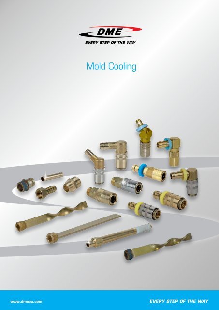
Mold Cooling
PTLH<br />
VM<br />
CONNECTOR PLUGS<br />
FLOW CHANNEL<br />
Jiffy<br />
for max. Ød = 6 --> diagram N6<br />
for max. Ød = 9 --> diagram N9<br />
for max. Ød = 16 --> diagram N16<br />
Euro<br />
for max. Ød = 6 --> diagram 9<br />
for max. Ød = 9 --> diagram 13<br />
INTERN INTERNE<br />
INTERN<br />
P. 10/11<br />
P. 12/13<br />
P. 14/15<br />
P. 30/31<br />
P. 32/33<br />
17/07/2012
CAD reference point<br />
17/07/2012<br />
09/04/2010<br />
09/04/2010<br />
09/04/2010<br />
09/04/2010<br />
<strong>DME</strong> Standard - Jiffy-Tite Connectors<br />
<strong>DME</strong> Jiffy-Tite plugs used with <strong>DME</strong> Jiffy-Tite<br />
(flow-through) type sockets and <strong>DME</strong> Jiffy-<br />
Matic (automatic shut off type) sockets are<br />
designed for use with plastics molds and die<br />
cast dies in water, air or oil lines. They feature<br />
a combination brass and stainless steel leak<br />
proof construction; have a maximum rated<br />
capacity of 13 bar and withstand temperatures<br />
of up to 200°C with supplied Viton seals.<br />
<strong>DME</strong> Jiffy-Tite and Jiffy-Matic sockets can be<br />
used interchangeably with the same Jiffy-Tite<br />
plugs already in your mold or die. Comparable<br />
sizes of both type sockets have the same OD<br />
permitting interchangeability even when the<br />
plugs are flush mounted. Seals and hose barbs<br />
are easily replaceable saving cost.<br />
www.dmeeu.com<br />
Euro Push-to-Lock<br />
<strong>DME</strong> Euro Series sockets used with special<br />
Push-to-Locktm hose do not require the use of a<br />
hose clamp for hose retention. the special hose<br />
is simply pushed onto the stem and will stay on<br />
without any additional fasteners, even under<br />
conditions of severe temperature, vibration<br />
and pressure. the sockets have a yellow plastic<br />
collar, purely for identification, to cover the cut<br />
end of the hose.<br />
Euro sockets are compatible with standard<br />
sockets/plugs. they are made of exactly the<br />
same brass and use the same high quality Viton<br />
seals.<br />
Use special Push-to-Locktm hose (PtLH) only.<br />
Euro connector sockets are for use with water<br />
and water-based coolants only. Although the<br />
Sockets are suitable for temperatures to 200°C<br />
observe the temperature ratings of the hose<br />
(standard 85°C). Never exceed 13 bar<br />
www.dmeeu.com<br />
Cooling Manifold<br />
• no loss in pressure due to long hoses or<br />
too many flow meters<br />
• efficient parallel moldcooling with shorter<br />
cycle times<br />
• easily install and group cooling<br />
connections and hoses<br />
• in- and outlets can be connected<br />
seperately<br />
• hose lengths can be reduced, enabling<br />
the molder to work with lower pressure in<br />
the system<br />
• cooling manifold can be installed<br />
horizontally and vertically<br />
www.dmeeu.com<br />
Technical Data<br />
www.dmeeu.com<br />
Content<br />
<strong>DME</strong> Jiffy Series<br />
Couplings.........................................................................................................................................................................................1<br />
Push-to-Lock............................................................................................................................................................................17<br />
Spare Parts....................................................................................................................................................................................21<br />
Euro Series<br />
Couplings......................................................................................................................................................................................24<br />
Push-to-Lock............................................................................................................................................................................33<br />
Safety Couplings.......................................................................................................................................................................36<br />
Accessories<br />
Nipples............................................................................................................................................................................................37<br />
Hoses...............................................................................................................................................................................................41<br />
Clamps............................................................................................................................................................................................42<br />
Baffles..............................................................................................................................................................................................45<br />
Cooling Cores.............................................................................................................................................................................56<br />
Duo Press ......................................................................................................................................................................................57<br />
Heat Transfer Rods...................................................................................................................................................................58<br />
O-rings............................................................................................................................................................................................65<br />
Cooling Manifold......................................................................................................................................................................69<br />
Technical Data<br />
Technical Data............................................................................................................................................................................73<br />
www.dmeeu.com
<strong>DME</strong> Standard - Jiffy-Tite Connectors<br />
<strong>DME</strong> Jiffy-Tite plugs used with <strong>DME</strong> Jiffy-Tite<br />
(flow-through) type sockets and <strong>DME</strong> Jiffy-<br />
Matic (automatic shut off type) sockets are<br />
designed for use with plastics molds and die<br />
cast dies in water, air or oil lines. They feature<br />
a combination brass and stainless steel leak<br />
proof construction; have a maximum rated<br />
capacity of 13 bar and withstand temperatures<br />
of up to 200°C with supplied Viton seals.<br />
<strong>DME</strong> Jiffy-Tite and Jiffy-Matic sockets can be<br />
used interchangeably with the same Jiffy-Tite<br />
plugs already in your mold or die. Comparable<br />
sizes of both type sockets have the same OD<br />
permitting interchangeability even when the<br />
plugs are flush mounted. Seals and hose barbs<br />
are easily replaceable saving cost.<br />
www.dmeeu.com
Cooling Items<br />
Jiffy Tite Range<br />
The Jiffy-Tite plugs and sockets provide a quick connect & disconnect method of changing heating & cooling hoses to the<br />
mold, as well as, from water manifolds or supply source. It is important to cool the mold so that the plastic material cools<br />
as quickly as possible to set up the part sufficiently so that it can be ejected from the mold as quick as possible for short<br />
cycle time. This helps to maintain part appearance & flow of material. Countersunk plugs can easily be connected and<br />
disconnected because of the extended sleeve. The angular connections prevent kinks from forming in the hose.<br />
Working Pressure<br />
PB = 13 bar, maximum static working pressure with safety factor 4 to 1.<br />
Working Temperature*<br />
-15°C up to +200°C depending on the medium.<br />
Advantages<br />
Available in single shut-off, double shut-off or straight-through versions. The shut-off couplings (with valve) are equipped<br />
with nickel plated sleeves for quick and accurate visual differentiation.<br />
Couplings foreseen with the Replaceable Viton® Seal. Easy to change with Seal Removal Tool for customers benefit.<br />
They are known for their larger flow through-holes what results in more flow, faster cycle times and greater cooling.<br />
Jiffy-Seal® Pre-applied Thread Sealant on all male nipples<br />
Material Coupling<br />
Back Body<br />
Valve Body<br />
Sleeve<br />
Sleeve<br />
Valve<br />
Locking Balls<br />
Seals<br />
Spring & Locking Rings<br />
Plug<br />
Plug Profile<br />
Adapter<br />
Valve<br />
Spring and Locking Ring<br />
Seal<br />
Safety instructions:<br />
2 - www.dmeeu.com<br />
Brass<br />
Brass<br />
Brass (without Valve)<br />
Brass, Nickel Plated (with valve)<br />
Brass<br />
AISI 420<br />
Viton®<br />
AISI 301<br />
Brass<br />
Brass<br />
Brass<br />
AISI 301<br />
Viton®<br />
In the event of incorrect selection, incorrect and improper use, quick connect couplings and their accessories may cause<br />
damage to property and personal injury !<br />
The consequences of incorrect selection, incorrect and improper use may be:<br />
2 Ends of hoses, coupling and plug components or accessories may fly around.<br />
2 Contact with fluids that are damaging to the health, toxic, cold or hot.<br />
2 Leakage of fluids under high pressure.<br />
2 Explosion or combustion of leaking fluids.<br />
2 Injuries and damage caused by uncontrolled movements of system parts through drop in fluid pressure.<br />
17/07/2012
17/07/2012<br />
Operating Instructions<br />
2 Coupling with two-handed operation : Couplings is effected by pushing back the sleeve, and at the same time,<br />
pushing the connector into the coupling. During the coupling make sure that the connector is pushed into the<br />
coupling as far as it will go. When the maximum push-in position has been reached, the sleeve must be released and<br />
only then the connector. The sleeve must move towards the connector until it reaches the same initial position as<br />
before actuation. It is important to check whether the lock has snapped into place by pulling the connector.<br />
2 Caution ! Fluid may leak during coupling, especially with couplings that are under pressure. Make sure that any fluid<br />
that may leak under these circumstances does not create any hazard.<br />
2 When Uncoupling without the built in valve (Jiffy-Tite®), it is essential that the fluid should be shut off before<br />
uncoupling. Uncoupling is affected by pushing back the sleeve. The coupling valve shuts off any further fluid<br />
supply, and at the same time the connector is pressed out of the coupling by the remaining fluid pressure and the<br />
valve spring. During uncoupling the connector must be firmly held in the hand in order to prevent it from spinning<br />
dangerously out of control.<br />
Installation instructions<br />
Before installation make sure that the selected quick coupling is suitable for the fluid to flow through it, with respect to<br />
its design , materials, seals, working pressure and working temperature.<br />
2 The installation location of the quick coupling or the connector must be in such a way that the operator cannot injure<br />
himself through dangerous locations in the direct vicinity, eg. slipping, jamming, contamination or burning<br />
2 When using hoses, the permissible operating pressure and temperature must not be exceeded. The hoses must be<br />
secured against slipping off the fittings with hose clamps.<br />
2 The recommended direction of flow is from the coupling to the connector, insofar as nothing else is specified.<br />
2 If no Jiffy-Seal® Thread sealant available the threads must be coated with suitable sealing agents such as PTFE tape.<br />
2 Covering caps and protected connectors are recommended for uncoupled connectors and couplings in order to<br />
prevent damage or contamination.<br />
Maintenance Instructions<br />
<strong>DME</strong> couplings are largely maintenance-free with standard applications and careful treatment, with the correct<br />
selection of coupling type and materials. We recommend a regular custom-made maintenance procedure, covering<br />
the following points:<br />
2 External visual inspection of the <strong>DME</strong> coupling combination. In the<br />
event of dirt accumulation in the functional area of coupling and<br />
connector this must be cleaned. The following properties require<br />
replacement of the parts in question: torn, damaged, very dirty or<br />
corroded parts, leaks in clutch of connector parts.<br />
2 Replacement intervals for quick connect couplings or replacement of<br />
the Viton seal with the Jiffy Seal Removal Tool<br />
JSTK-235<br />
Operating Combinations<br />
PCS-Series** male plugs<br />
with SVK-Series sockets (equivalent size)<br />
VALVES CLOSED<br />
VALVES OPEN<br />
** The PCS-Series Jiffy Matic Male plugs can only be used for two-way shut-offs and must be used with the SVK-Series Jiffy-Matic Sockets.<br />
Cooling Items<br />
Std. male, female or extension plugs<br />
with SVK-Series sockets (equivalent size)<br />
VALVE CLOSED<br />
VALVE OPEN<br />
www.dmeeu.com - 3
P.40<br />
P.40<br />
P.37<br />
P.37<br />
P.38<br />
<strong>DME</strong> Jiffy N6<br />
FLOW CHANNEL<br />
max. Ød = 6<br />
4 - www.dmeeu.com<br />
P.11<br />
P.12<br />
P.13<br />
P.12<br />
P.10<br />
P.13<br />
P.11<br />
P.20<br />
17/07/2012
17/07/2012<br />
P.14<br />
P.14<br />
P.14<br />
P.16<br />
P.16<br />
P.15<br />
P.15<br />
P.16<br />
P.16<br />
P.15<br />
P.20<br />
P.41<br />
P.41<br />
P.34<br />
Not for “Push-to-Lock”<br />
For “Push-to-Lock”<br />
<strong>DME</strong> Jiffy N6<br />
Spare Parts<br />
Accessories<br />
P.42<br />
P.42<br />
P.42<br />
www.dmeeu.com - 5<br />
P.51<br />
P.37<br />
P.37<br />
P.39
FLOW CHANNEL<br />
max. Ød = 9<br />
P.40<br />
P.40<br />
P.37<br />
P.37<br />
P.38<br />
<strong>DME</strong> Jiffy N9<br />
6 - www.dmeeu.com<br />
P.11<br />
P.12<br />
P.13<br />
P.12<br />
P.10<br />
P.10<br />
P.13<br />
P.11<br />
P.20<br />
17/07/2012
17/07/2012<br />
P.14<br />
P.14<br />
P.14<br />
P.16<br />
P.16<br />
P.15<br />
P.15<br />
P.16<br />
P.16<br />
P.15<br />
P.20<br />
P.41<br />
P.41<br />
P.34<br />
Not for “Push-to-Lock”<br />
For “Push-to-Lock”<br />
<strong>DME</strong> Jiffy N9<br />
Spare Parts<br />
Accessories<br />
P.42<br />
P.42<br />
P.42<br />
P.51<br />
P.37<br />
P.37<br />
P.39<br />
www.dmeeu.com - 7
FLOW CHANNEL<br />
<strong>DME</strong> Jiffy N16<br />
P.40<br />
P.37<br />
P.37<br />
P.38<br />
8 - www.dmeeu.com<br />
P.11<br />
P.13<br />
P.10<br />
P.10<br />
P.11<br />
17/07/2012
17/07/2012<br />
P.14<br />
P.14<br />
P.14<br />
P.16<br />
P.16<br />
P.15<br />
P.15<br />
P.16<br />
P.16<br />
P.15<br />
<strong>DME</strong> Jiffy N16<br />
Spare Parts<br />
www.dmeeu.com - 9
<strong>DME</strong> Jiffy<br />
N<br />
N<br />
N<br />
FN<br />
All Male plugs (including PCS-Series) and extension plugs are now supplied with Jiffy-seal thread sealant .<br />
Eliminating the initial need for joint tape or compound.<br />
10 - www.dmeeu.com<br />
Connector plugs with PTFE seal<br />
Connector plug with inner hexagon<br />
Connector plugs for FSK and FSVK<br />
Mat.: Brass<br />
REF R d1 d L A B H SW Series<br />
N 6-1/8” A 1/8” BSPT 9,4 6 24,0 22 18 17 13 N6<br />
N 6-MA M10x1 9,4 6 23,0 22 18 17 13 N6<br />
N 6-1/4” A 1/4” BSPT 9,4 6 29,0 26 20 19 16 N6<br />
N 6-3/8” A 3/8” BSPT 9,4 6 30,0 30 22 21 19 N6<br />
N 9-1/8” A 1/8” BSPT 13,5 9 30,0 26 26 25 14 N9<br />
N 9-1/4” A 1/4” BSPT 13,5 9 34,0 26 26 25 16 N9<br />
N 9-3/8” A 3/8” BSPT 13,5 9 34,0 30 28 26 19 N9<br />
N 9-MA M10x1 13,5 6 29,5 26 26 25 16 N9<br />
N 9-1/2” A 1/2” BSPT 13,5 9 39,0 37 28 26 24 N9<br />
N 16-1/2” A 1/2” BSPT 19,9 16 44,0 32 38 37 22 N16<br />
N 16-3/4” A 3/4” BSPT 19,9 16 45,0 38 40 38 29 N16<br />
Mat.: Brass<br />
REF R d1 d L D1 A B H Series<br />
N 9-3/8” AH 3/8” BSPT 13,5 9 34 21 30 28 26 N9<br />
Connector plug with inner hexagon<br />
Mat.: Brass<br />
REF R d d1 L l1 A B H SW SW1 Series<br />
N6 1/8 AHN 1/8” BSPT 6 9,4 23 9 22 16 14 11 5 N6<br />
N6 M10x1 AHN M10x1 6 9,4 23 9 22 16 14 11 5 N6<br />
N6 1/4 AHN 1/4” BSPT 6 9,4 28 14 26 16 14 16 5 N6<br />
N6 M14x1,5 AHN M14x1,5 6 9,4 28 14 26 16 14 16 5 N6<br />
N9 1/4 AHN 1/4” BSPT 9,3 13,5 34 14 26 22 20 16 8 N9<br />
N9 M14x1,5 AHN M14x1,5 9,3 13,5 34 14 26 22 20 16 8 N9<br />
N9 M16x1,5 AHN M16x1,5 9,3 13,5 35 14 30 23 21 19 8 N9<br />
N9 3/8 AHN 3/8” BSPT 9,3 13,5 35 14 30 23 21 19 8 N9<br />
• the Jiffy inner hexacon connector plugs enable easy mounting where space is limited when<br />
working with a wrench<br />
• complete range supplied with thread sealant<br />
Mat.: Brass<br />
REF Rp A B d1 d L l1 SW Series<br />
FN 9-14 A 1/4” BSP 30 23,5 13,5 9 34 11,5 16 N9<br />
FN 9-38 A 3/8” BSP 30 23,5 13,5 9 34 11,5 19 N9<br />
FN 16-38 A 3/8” BSP 32 29,5 19,9 15 40 11,5 22 N16<br />
FN 16-38 AL 3/8” BSP 32 29,5 19,9 15 53 24,5 22 N16<br />
FN 16-12 A 1/2” BSP 32 29,5 19,9 15 45 16,5 22 N16<br />
FN 16-12 AL 1/2” BSP 32 29,5 19,9 15 54 25,5 22 N16<br />
CAD reference point<br />
17/07/2012
CAD reference point<br />
17/07/2012<br />
Shut-off connector plugs for SVK<br />
Connector plugs<br />
Connector plugs for FSK and FSVK<br />
Socket wrenches<br />
Mat.: St. 55 DIN 2391<br />
REF L SW1 SW2<br />
DS 1314 140 13 14<br />
DS 1617 150 16 17<br />
DS 1922 170 19 22<br />
DS 2427 190 24 27<br />
Mat.: Brass<br />
REF R d1 d L A B H SW Series<br />
PCS 6-14 A 1/4” BSPT 9,4 6 29,0 28 20 18 16 N6<br />
PCS 6-38 A 3/8” BSPT 9,4 6 29,5 30 20 18 19 N6<br />
PCS 9-14 A 1/4” BSPT 13,5 9 34,0 28 27 25 16 N9<br />
PCS 9-38 A 3/8” BSPT 13,5 9 34,0 30 28 26 19 N9<br />
PCS 9-12 A 1/2” BSPT 13,5 9 37,0 35 28 26 24 N9<br />
PCS 16-12 A 1/2” BSPT 19,9 15 44,4 35 34 32 7/8” N16<br />
PCS 16-34 A 3/4” BSPT 19,9 15 44,4 42 32 30 1 1/8” N16<br />
Mat.: Brass<br />
REF Rp d1 d L SW Series<br />
N 6-1/8” I 1/8” BSP 9,4 6 28 13 N6<br />
N 6-1/4” I 1/4” BSP 9,4 6 32 16 N6<br />
N 6-3/8” I 3/8” BSP 9,4 6 34 19 N6<br />
N 9-1/4” I 1/4” BSP 13,5 9 37 16 N9<br />
N 9-3/8” I 3/8” BSP 13,5 9 39 19 N9<br />
N 9-1/2” I 1/2” BSP 13,5 9 46 24 N9<br />
Mat.: Brass<br />
REF Rp d1 d L SW Series<br />
FN 9-18 I 1/8” BSP 13,5 9 32 16 N9<br />
FN 9-14 I 1/4” BSP 13,5 9 37 19 N9<br />
FN 16-38 I 3/8” BSP 19,9 15 40 22 N16<br />
FN 16-12 I 1/2” BSP 19,9 15 45 24 N16<br />
<strong>DME</strong> Jiffy<br />
PCS<br />
N<br />
FN<br />
DS<br />
www.dmeeu.com - 11
<strong>DME</strong> Jiffy<br />
ATN<br />
EJP<br />
EJP<br />
12 - www.dmeeu.com<br />
Angle nipples<br />
Extension pipes<br />
Extension pipes<br />
Mat.: Brass<br />
REF R d1 d2 L L1 L2 SW Series<br />
ATN 9 1/8” BSPT 9,4 6 27 9 23,0 11 N6<br />
ATN 13 1/4” BSPT 13,5 9 34 9 24,5 15 N9<br />
Mat.: Brass<br />
REF Rp d1 d L A SW Series<br />
EJP 2514 1/8” BSP 9,4 6,3 100 61 12 N6<br />
EJP 2516 1/8” BSP 9,4 6,3 150 61 12 N6<br />
EJP 2518 1/8” BSP 9,4 6,3 200 61 12 N6<br />
EJP 2524 1/4” BSP 9,4 6,3 100 61 15 N6<br />
EJP 2526 1/4” BSP 9,4 6,3 150 61 15 N6<br />
EJP 2528 1/4” BSP 9,4 6,3 200 61 15 N6<br />
EJP 2534 3/8” BSP 9,4 6,3 100 61 18 N6<br />
EJP 2536 3/8” BSP 9,4 6,3 150 61 18 N6<br />
EJP 2538 3/8” BSP 9,4 6,3 200 61 18 N6<br />
Mat.: Brass<br />
REF Rp d1 d L A SW Series<br />
EJP 3514 1/8” BSP 13,5 6,3 100 61 15 N9<br />
EJP 3516 1/8” BSP 13,5 6,3 150 61 15 N9<br />
EJP 3518 1/8” BSP 13,5 6,3 200 61 15 N9<br />
EJP 3524 1/4” BSP 13,5 9,5 100 61 15 N9<br />
EJP 3526 1/4” BSP 13,5 9,5 150 61 15 N9<br />
EJP 3528 1/4” BSP 13,5 9,5 200 61 15 N9<br />
EJP 3534 3/8” BSP 13,5 9,5 100 61 18 N9<br />
EJP 3536 3/8” BSP 13,5 9,5 150 61 18 N9<br />
EJP 3538 3/8” BSP 13,5 9,5 200 61 18 N9<br />
CAD reference point<br />
17/07/2012
CAD reference point<br />
17/07/2012<br />
Brass extension pipes<br />
Brass extension pipes<br />
Hose Nipples<br />
Mat.: Brass<br />
REF R L SW d d1 d2 Series<br />
BEP-1810 1/8” BSPT 100 11 6 9,4 10 N6<br />
BEP-1415 1/4” BSPT 150 15 9 13,5 14 N9<br />
Mat.: Brass<br />
REF L SW d d1 d2 Series<br />
BEP-1815 150 11 6 9,4 10 N6<br />
BEP-1825 250 11 6 9,4 10 N6<br />
BEP-1425 250 15 9 13,5 14 N9<br />
Mat.: Brass<br />
REF d d1 d2 L1 L fits hose ID Series<br />
STN 9 6,0 9,4 10 17 39,0 - N6<br />
STN 13 9,0 13,5 14 21 41,0 - N9<br />
STN 19 15,5 19,9 20 46 91,0 - N16<br />
STN 9 PL 6,0 9,4 - 24 37,0 3/8” N6<br />
STN 13 PL 9,0 13,5 - 28 48,0 1/2” N9<br />
STN 19 PL 14,0 19,9 - 28 63,5 3/4” N16<br />
<strong>DME</strong> Jiffy<br />
BEP<br />
BEP<br />
STN / STN PL<br />
www.dmeeu.com - 13
<strong>DME</strong> Jiffy<br />
SVK<br />
SVK (90°)<br />
SVK (45°)<br />
Jiffy-Tite® Sockets<br />
Flow-thru type<br />
VALVES CLOSED<br />
Jiffy-Tite sockets have a large thru hole to provide<br />
unrestricted flow.<br />
VALVES OPEN<br />
14 - www.dmeeu.com<br />
Jiffy Matics straight with valve<br />
Jiffy Matics 90° with valve<br />
Jiffy Matics 45° with valve<br />
Jiffy-Matic® Sockets<br />
Automatic shut-off type<br />
VALVE CLOSED<br />
VALVE OPEN<br />
Mat.: Brass-stainless steel<br />
REF d1 d2 d D l1 l2 Series<br />
SVK-106 9,5 5 7,3 17,0 27 57 N6<br />
SVK-109 9,5 6 10,5 17,0 27 57 N6<br />
SVK-111 13,6 9 12,2 22,6 27 68 N9<br />
SVK-113 13,6 9 14,0 22,6 27 68 N9<br />
SVK-119 20,0 16 20,0 30,0 46 103 N16<br />
Mat.: Brass-stainless steel<br />
REF d1 d2 d D A l1 l2 Series<br />
SVK-206 9,5 5 7,3 17,0 38 27 34 N6<br />
SVK-209 9,5 6 10,5 17,0 38 27 34 N6<br />
SVK-211 13,6 9 12,2 22,6 52 27 37 N9<br />
SVK-213 13,6 9 14,0 22,6 52 27 37 N9<br />
SVK-219 20,0 16 20,0 30,0 74 46 69 N16<br />
Mat.: Brass-stainless steel<br />
REF d1 d2 d D A l1 l2 Series<br />
SVK-306 9,5 5 7,3 17,0 38 27 34 N6<br />
SVK-309 9,5 6 10,5 17,0 38 27 34 N6<br />
SVK-311 13,6 9 12,2 22,6 52 27 37 N9<br />
SVK-313 13,6 9 14,0 22,6 52 27 37 N9<br />
SVK-319 20,0 16 20,0 30,0 74 46 69 N16<br />
Jiffy-Tite & Jiffy-Matic<br />
sockets can be used interchangeably<br />
with the same<br />
Jiffy-Tite plugs already in<br />
your mold or die. Comparable<br />
sizes of both type<br />
sockets have the same O.D.,<br />
permitting interchangeability<br />
even when the plugs<br />
are flush mounted.<br />
CAD reference point<br />
17/07/2012
CAD reference point<br />
17/07/2012<br />
Jiffy Tites straight<br />
Jiffy Tites 90°<br />
Jiffy Tites 45°<br />
Mat.: Brass-stainless steel<br />
REF d1 d2 d D l1 l2 Series<br />
SK-106 9,5 5 7,3 17,0 25 52 N6<br />
SK-109 9,5 6 10,5 17,0 25 52 N6<br />
SK-111 13,6 9 12,2 22,6 25 62 N9<br />
SK-113 13,6 9 14,0 22,6 25 62 N9<br />
SK-119 20,0 16 20,0 30,0 32 77 N16<br />
Mat.: Brass-stainless steel<br />
REF d1 d2 d D A l1 l2 Series<br />
SK-206 9,5 5 7,3 17,0 38 27 34 N6<br />
SK-209 9,5 6 10,5 17,0 38 27 34 N6<br />
SK-211 13,6 9 12,2 22,6 52 27 37 N9<br />
SK-213 13,6 9 14,0 22,6 52 27 37 N9<br />
SK-219 20,0 16 20,0 30,0 68 46 69 N16<br />
Mat.: Brass-stainless steel<br />
REF d1 d2 d D A l1 l2 Series<br />
SK-306 9,5 5 7,3 17,0 38 27 34 N6<br />
SK-309 9,5 6 10,5 17,0 38 27 34 N6<br />
SK-311 13,6 9 12,2 22,6 52 27 37 N9<br />
SK-313 13,6 9 14,0 22,6 52 27 37 N9<br />
SK-319 20,0 16 20,0 30,0 67 46 69 N16<br />
<strong>DME</strong> Jiffy<br />
SK<br />
SK (90°)<br />
SK (45°)<br />
www.dmeeu.com - 15
<strong>DME</strong> Jiffy<br />
SVK 200-300-500<br />
FSVK<br />
SK 200-300-500<br />
FSK<br />
16 - www.dmeeu.com<br />
Female Jiffy Matics with valve<br />
Jiffy Matics with valve<br />
Female Jiffy Tites<br />
Jiffy Tites<br />
Mat.: Brass-stainless steel<br />
REF Rp d l2 D SW Series<br />
SVK-200 1/8” BSP 9,5 39 17,0 1/2” N6<br />
SVK-300 1/4” BSP 13,6 53 22,6 3/8” N9<br />
SVK-500 1/2” BSP 20,0 57 30,0 1 1/8” N16<br />
Mat.: Brass-stainless steel<br />
REF Rp d L D A B SW Series<br />
FSVK-106 V 1/4” BSP 9,5 46 17,0 30,5 8,0 1/2” N6<br />
FSVK-111 V 3/8” BSP 13,6 60 22,6 41,0 8,5 3/8” N9<br />
FSVK-119 V 1/2” BSP 17,5 76 30,6 57,0 7,0 1 1/8” N16<br />
Mat.: Brass-stainless steel<br />
REF Rp d l2 D SW Series<br />
SK-200 1/8” BSP 9,5 39 17,0 1/2” N6<br />
SK-300 1/4” BSP 13,6 53 22,6 3/8” N9<br />
SK-500 1/2” BSP 20,0 59 30,0 1 1/8” N16<br />
Mat.: Brass-stainless steel<br />
REF Rp d L D A B SW Series<br />
FSK-206 V 1/4” BSP 9,5 46 17,0 30,5 7,0 1/2” N6<br />
FSK-211 V 3/8” BSP 13,6 60 22,6 41,0 8,0 3/8” N9<br />
FSK-219 V 1/2” BSP 17,5 72 30,6 51,0 8,5 1 1/8” N16<br />
CAD reference point<br />
17/07/2012
17/07/2012<br />
<strong>DME</strong> Push-to-Lock<br />
<strong>DME</strong> Jiffy-Lok TM sockets used with special Pushto-Lock<br />
TM hose do not require the use of a hose<br />
clamp for hose retention. The special hose is<br />
simply pushed onto the stem and will stay on<br />
without any additional fasteners, even under<br />
conditions of severe temperature, vibration and<br />
pressure. The sockets have a blue plastic collar,<br />
purely for identification, to cover the cut end of<br />
the hose.<br />
Jiffy-Lok TM sockets are compatible with standard<br />
Jiffy sockets/plugs. They are made of exactly the<br />
same brass and use the same high quality Viton<br />
seals.<br />
Use special Push-to-Lock TM hose (PTLH) only.<br />
Jiffy-Lok TM connector sockets are for use with<br />
water and water-based coolants only. Although<br />
the Sockets are suitable to temperatures to<br />
200°C observe the temperature ratings of the<br />
hose. Never exceed 13 bar<br />
www.dmeeu.com
<strong>DME</strong> Jiffy<br />
SVK - PL<br />
SVK - 90° PL<br />
SVK - 45° PL<br />
Jiffy-Lok® Connector Sockets<br />
With clampless hose stems for use with “Push-to-Lock” type hose<br />
18 - www.dmeeu.com<br />
Jiffy Lok straight with valve “Push-to-Lock”<br />
Jiffy Lok 90° with valve “Push-to-Lock”<br />
Jiffy Lok 45° with valve “Push-to-Lock”<br />
3 Saves set-up time by eliminating the need for hose clamps.<br />
3 Popular sizes for interchangeability with existing Jiffy-Tite, Jiffy-Matic sockets.<br />
3 More compact and consistently sized than competitive sockets.<br />
3 Leakproof brass and stainless steel construction.<br />
3 Replaceable seals and valves for long service life.<br />
Mat.: Brass-stainless steel<br />
REF d1 d2 fits D l1 l2 Series<br />
SVK-106-PL 9,5 5 1/4” 17,0 27 57 N6<br />
SVK-109-PL 9,5 6 3/8” 17,0 27 57 N6<br />
SVK-111-PL 13,6 6 3/8” 22,6 27 68 N9<br />
SVK-113-PL 13,6 9 1/2” 22,6 27 68 N9<br />
Mat.: Brass-stainless steel<br />
REF d1 d2 fits D A l1 l2 Series<br />
SVK-206-PL 9,5 5 1/4” 17,0 38 27 34 N6<br />
SVK-209-PL 9,5 6 3/8” 17,0 38 27 34 N6<br />
SVK-211-PL 13,6 6 3/8” 22,6 52 27 37 N9<br />
SVK-213-PL 13,6 9 1/2” 22,6 52 27 37 N9<br />
Mat.: Brass-stainless steel<br />
REF d1 d2 fits D A l1 l2 Series<br />
SVK-306-PL 9,5 5 1/4” 17,0 38 27 34 N6<br />
SVK-309-PL 9,5 6 3/8” 17,0 38 27 34 N6<br />
SVK-311-PL 13,6 6 3/8” 22,6 52 27 37 N9<br />
SVK-313-PL 13,6 9 1/2” 22,6 52 27 37 N9<br />
CAD reference point<br />
17/07/2012
CAD reference point<br />
17/07/2012<br />
Jiffy Lok Straight “Push-to-Lock”<br />
Jiffy Lok 90° “Push-to-Lock”<br />
Jiffy Lok 45° “Push-to-Lock”<br />
Hose Nipples<br />
Mat.: Brass-stainless steel<br />
REF d1 d2 fits D l1 l2 Series<br />
SK-106-PL 9,5 5 1/4” 17,0 25 52 N6<br />
SK-109-PL 9,5 6 3/8” 17,0 25 52 N6<br />
SK-111-PL 13,6 6 3/8” 22,6 25 62 N9<br />
SK-113-PL 13,6 9 1/2” 22,6 25 62 N9<br />
SK-119-PL 20,0 14 3/4” 30,0 32 77 N16<br />
Mat.: Brass-stainless steel<br />
REF d1 d2 fits D A l1 l2 Series<br />
SK-206-PL 9,5 5 1/4” 17,0 38 27 34 N6<br />
SK-209-PL 9,5 6 3/8” 17,0 38 27 34 N6<br />
SK-211-PL 13,6 6 3/8” 22,6 52 27 37 N9<br />
SK-213-PL 13,6 9 1/2” 22,6 52 27 37 N9<br />
SK-219-PL 20,0 14 3/4” 30,0 68 46 69 N16<br />
Mat.: Brass-stainless steel<br />
REF d1 d2 fits D A l1 l2 Series<br />
SK-306-PL 9,5 5 1/4” 17,0 38 27 34 N6<br />
SK-309-PL 9,5 6 3/8” 17,0 38 27 34 N6<br />
SK-311-PL 13,6 6 3/8” 22,6 52 27 37 N9<br />
SK-313-PL 13,6 9 1/2” 22,6 52 27 37 N9<br />
SK-319-PL 20,0 14 3/4” 30,0 67 46 69 N16<br />
Mat.: Brass<br />
REF d d1 d2 L1 L fits hose ID Series<br />
STN 9 PL 6,0 9,4 - 24 37,0 3/8” N6<br />
STN 13 PL 9,0 13,5 - 28 48,0 1/2” N9<br />
STN 19 PL 14,0 19,9 - 28 63,5 3/4” N16<br />
<strong>DME</strong> Jiffy<br />
SK - PL<br />
SK - 90° PL<br />
SK - 45° PL<br />
STN PL<br />
www.dmeeu.com - 19
<strong>DME</strong> Jiffy<br />
JCB-SV<br />
JCB<br />
JBT<br />
JCB-200-300<br />
20 - www.dmeeu.com<br />
O-Ring<br />
Jiffy Matics Socket Adapter with valve<br />
Jiffy Tite Socket Adapter<br />
Brass Tube<br />
Sparepart for coolant bridge<br />
REF Series<br />
JCB-0011 N6<br />
JCB-0013 N9<br />
200-8 N6<br />
300-8 N9<br />
Mat.: Brass. Max. T: 200°C & 13,7 bar<br />
REF d1 D A B C Description Series<br />
JCB-0200 SV 9,5 17,0 44,2 37,3 30,5 TWO - WAY SHUTOFF N6<br />
JCB-0300 SV 13,6 22,6 57,4 49,3 41,4 TWO - WAY SHUTOFF N9<br />
Provides more compact port-to-port connections than conventional hose methodes.3 Socket<br />
adapter marked with cut-line groove for quick sizing of brass tube length.<br />
Mat.: Brass. Max. T: 200°C & 13,7 bar<br />
REF d1 D A B C Description Series<br />
JCB-0200 9,5 17,0 44,2 37,3 30,5 FLOW - THRU N6<br />
JCB-0300 13,6 22,6 57,4 49,3 41,4 FLOW - THRU N9<br />
Mat.: Brass<br />
REF d1 D R L L1 Series<br />
JBT 0450 5,4 7,9 0,3 457 1,75 N6<br />
JBT 0570 7,8 11,1 0,3 457 2,00 N9<br />
Mat.: Viton O-Ring<br />
CAD reference point<br />
17/07/2012
CAD reference point<br />
17/07/2012<br />
Collar springs<br />
REF Series<br />
200-3 N6<br />
300-3 N9<br />
500-3 N16<br />
Retainer rings<br />
REF Series<br />
200-4 N6<br />
300-4 N9<br />
500-4 N16<br />
Stainless steel balls<br />
REF Series<br />
200-5 N6<br />
300-5 N9<br />
500-5 N16<br />
Seals<br />
REF Series<br />
200-8 N6<br />
300-8 N9<br />
500-8 N16<br />
Mat.: Viton 220°C<br />
<strong>DME</strong> Jiffy - spare parts<br />
200 - 300 - 500<br />
200 - 300 - 500<br />
200 - 300 - 500<br />
200 - 300 - 500<br />
www.dmeeu.com - 21
<strong>DME</strong> Jiffy - spare parts<br />
N / DK<br />
JSTK<br />
SEA<br />
DB<br />
22 - www.dmeeu.com<br />
Valves + springs<br />
REF Series<br />
N6-601 N6<br />
N9-601 N9<br />
DK-N16 V N16<br />
Jiffy Tite seal removal kit<br />
REF<br />
JSTK 235<br />
Seals are replaceable saving costs.<br />
When worn out, simply replace the seal instead of the whole coupling.<br />
The Jiffy-Tite seal removal kit can be used for removal of connector seals from<br />
Jiffy-Matic sockets. Can also be used with Jiffy-Tite sockets to provide easier seal<br />
removal.<br />
Adhesives<br />
REF T Info<br />
SEA 03 204°C 10g<br />
Sealing tapes<br />
REF L B<br />
DB 1206 12 m 6 mm<br />
DB 1212 12 m 12 mm<br />
Max. T: 204°C - 10g<br />
Mat.: PTFE Max.T=250°C<br />
CAD reference point<br />
17/07/2012
CAD reference point<br />
17/07/2012<br />
Adapters<br />
Hose Nipples<br />
90° Angles<br />
45° Angles<br />
Mat.: Brass<br />
REF Rp1 Rp2 L I SW Series<br />
N6-18 UNEF 7/16”-32 1/8” BSP 13 8 13 N6<br />
N9-14 UNEF 5/8”-24 1/4” BSP 18 11 19 N9<br />
Mat.: Brass<br />
REF Rp d1 d L L1 SW Series<br />
N6-6M UNEF 7/16”-32 5 6 32 27 11 N6<br />
N6-9M UNEF 7/16”-32 6 9 32 27 11 N6<br />
N9-11M UNEF 5/8”-24 9 11 33 27 16 N9<br />
N9-13M UNEF 5/8”-24 9 13 33 27 16 N9<br />
500-19M BSP 1/2”-14 16 19 56 46 22 N16<br />
Mat.: Brass<br />
REF Rp1 Rp2 R SW Series<br />
N6-90 UNEF 7/16”-32 UNEF 7/16”-32 - 15 N6<br />
N9-90 UNEF 5/8”-24 UNEF 5/8”-24 - 21 N9<br />
500-90 - 1/2” NPT 1/2” BSPT 26 N16<br />
Mat.: Brass<br />
REF Rp1 Rp2 SW Series<br />
N6-45 UNEF 7/16”-32 UNEF 7/16”-32 15 N6<br />
N9-45 UNEF 5/8”-24 UNEF 5/8”-24 21 N9<br />
500-45 1/2” NPT 1/2” BSP 26 N16<br />
<strong>DME</strong> Jiffy - spare parts<br />
N<br />
N / 500<br />
N / 500<br />
N / 500<br />
www.dmeeu.com - 23
Euro 9<br />
FLOW CHANNEL<br />
P.29<br />
P.29<br />
P.28<br />
P.28<br />
P.29<br />
PL<br />
24 - www.dmeeu.com<br />
P.31<br />
P.31<br />
P.31<br />
P.30<br />
P.30<br />
P.30<br />
P.32<br />
P.32<br />
P.32<br />
P.32<br />
17/07/2012
17/07/2012<br />
P.38<br />
P.35<br />
P.37<br />
P.38<br />
P.41<br />
P.41<br />
P.34<br />
Not for “Push-to-Lock”<br />
For “Push-to-Lock”<br />
Accessories<br />
Euro 9<br />
www.dmeeu.com - 25<br />
P.42<br />
P.42<br />
P.42
P.29<br />
P.29<br />
P.28<br />
P.28<br />
P.29<br />
Euro 13<br />
FLOW CHANNEL<br />
max. Ød = 9<br />
PL<br />
26 - www.dmeeu.com<br />
P.31<br />
P.31<br />
P.31<br />
P.30<br />
P.30<br />
P.30<br />
P.32<br />
P.32<br />
P.32<br />
P.32<br />
17/07/2012
17/07/2012<br />
P.38<br />
P.35<br />
P.37<br />
P.38<br />
P.41<br />
P.41<br />
P.34<br />
Not for “Push-to-Lock”<br />
For “Push-to-Lock”<br />
Accessories<br />
Euro 13<br />
www.dmeeu.com - 27<br />
P.42<br />
P.42<br />
P.42
Euro<br />
ST 11<br />
ST 11<br />
ST 11<br />
ST 12<br />
28 - www.dmeeu.com<br />
Open Connector plug<br />
REF Rp d2 d4 L L1 P (bar) T (°C) SW<br />
ST 11 9-M8x0,75 M8x0,75 4,5 9 24 7 15 200 11<br />
ST 11 9-M10x1 M10x1 6,0 9 24 7 15 200 11<br />
ST 11 9-R1/8” 1/8” BSP 6,0 9 24 7 15 200 11<br />
ST 11 9-M14x1,5 M14x1,5 6,0 9 26 9 15 200 15<br />
ST 11 9 R1/4” 1/4” BSP 6,0 9 26 9 15 200 15<br />
ST 11 13-M14x1,5 M14x1,5 9,0 13 26 9 10 200 15<br />
ST 11 13 R1/4” 1/4” BSP 9,0 13 26 9 10 200 15<br />
ST 11 13 M16x1,5 M16x1,5 9,0 13 26 9 10 200 17<br />
ST 11 13-R3/8” 3/8” BSP 9,0 13 26 9 10 200 17<br />
Connector plug with inner hexagon<br />
Connector plug with inner hexagon<br />
Hose Nipples<br />
REF d1 d2 d4 L L1<br />
ST 12 9 9 6 9 40 17<br />
ST 12 13 13 9 13 41 25<br />
Mat.: Brass<br />
Mat.: Brass<br />
REF Rp d2 d4 L L1 P (bar) T (°C) SW SW1<br />
ST 11 9-R1/8” H 1/8” BSP 6 9 24 7 15 200 11 5<br />
ST 11 9-M10x1 H M10 x 1 6 9 24 7 15 200 11 5<br />
ST 11 9-R1/4” H 1/4” BSP 6 9 26 9 15 200 15 5<br />
ST 11 9-M14x1,5 H M14 x 1,5 6 9 26 9 15 200 15 5<br />
• the inner hexacon connector plugs enable easy mounting where space is limited when<br />
working with a wrench<br />
• complete range supplied with thread sealant<br />
Mat.: Brass<br />
REF Rp d2 d4 L L1 P (bar) T (°C) SW SW1<br />
ST 11 13-R1/4” H 1/4” BSP 9,3 13 26 9 15 200 15 8<br />
ST 11 13-M14x1,5 H M14 x 1,5 9,3 13 26 9 15 200 15 8<br />
ST 11 13-M16x1,5 H M16 x 1,5 9,3 13 26 9 15 200 17 8<br />
ST 11 13-R3/8” H 3/8” BSP 9,3 13 26 9 15 200 17 8<br />
Mat.: Brass<br />
CAD reference point<br />
17/07/2012
CAD reference point<br />
17/07/2012<br />
Shut-off Connector plug<br />
Angle Connector plugs<br />
Extension nipples<br />
Mat.: Brass, O-ring: Viton<br />
REF Rp d2 d4 L L1 P (bar) T (°C) SW<br />
ST 13 9-M14x1,5 M14x1,5 6 9 29 12 15 200 15<br />
ST 13 9-R1/4” 1/4” BSP 6 9 29 12 15 200 15<br />
ST 13 13-M16x1,5 M16x1,5 9 13 30 12 10 200 17<br />
ST 13 13-R3/8” 3/8” BSP 9 13 30 12 10 200 17<br />
REF d2 d4 d5 l3 L SW<br />
ST15 9x120 6 9 10 21 120 11<br />
ST 15 9x240 6 9 10 21 240 11<br />
ST 15 9x360 6 9 10 21 360 11<br />
ST 15 13x150 9 13 14 23 150 15<br />
ST 15 13x300 9 13 14 23 300 15<br />
ST 15 13x450 9 13 14 23 450 15<br />
Mat.: Brass<br />
REF R d2 d4 L L1 L2 SW<br />
ST 14 9-M8x0,75 M8x0,75 4,5 9 27 9 23 11<br />
ST 14 9-M10x1 M10x1 6,0 9 27 9 23 11<br />
ST 14 9-R1/8” 1/8” BSPT 6,0 9 27 9 23 11<br />
ST 14 13-M14x1,5 M14x1,5 9,0 13 34 9 25 15<br />
ST 14 13-R1/4” 1/4” BSPT 9,0 13 34 9 25 15<br />
Mat.: Brass<br />
Euro<br />
ST 13<br />
ST 14<br />
ST 15<br />
www.dmeeu.com - 29
Euro<br />
MK 10<br />
MK 12<br />
MK 15<br />
30 - www.dmeeu.com<br />
Quick Release coupling straight with valve<br />
Quick Release coupling 45° with valve<br />
Quick Release coupling 90° with valve<br />
Mat.: Brass, O-ring: Viton<br />
REF d1 d2 d3 d4 L L1 P (bar) T (°C)<br />
MK 10 - 9V 9 6 17 9 47 17 15 200<br />
MK 10 - 13V 13 9 22 13 61 25 10 200<br />
Mat.: Brass, O-ring: Viton<br />
REF d1 d2 d3 d4 L L1 P (bar) T (°C)<br />
MK 12 - 9V 9 6 17 9 41 17 15 200<br />
MK 12 - 13V 13 9 22 13 51 25 10 200<br />
Mat.: Brass, O-ring: Viton<br />
REF d1 d2 d3 d4 L L1 P (bar) T (°C)<br />
MK 15 - 9V 9 6 17 9 41 19 15 200<br />
MK 15 - 13V 13 9 22 13 51 28 10 200<br />
CAD reference point<br />
17/07/2012
CAD reference point<br />
17/07/2012<br />
Quick Release coupling straight<br />
Quick Release coupling 45°<br />
Quick Release coupling 90°<br />
Mat.: Brass, O-ring: Viton<br />
REF d1 d2 d3 d4 L L1 P (bar) T (°C)<br />
MK 100 - 9 9 6 17 9 47 17 15 200<br />
MK 100 - 13 13 9 22 13 61 25 10 200<br />
Mat.: Brass, O-ring: Viton<br />
REF d1 d2 d3 d4 L L1 P (bar) T (°C)<br />
MK 120 - 9 9 6 17 9 41 17 15 200<br />
MK 120 - 13 13 9 22 13 51 25 10 200<br />
Mat.: Brass, O-ring: Viton<br />
REF d1 d2 d3 d4 L L1 P (bar) T (°C)<br />
MK 150 - 9 9 6 17 9 41 19 15 200<br />
MK 150 - 13 13 9 22 13 51 28 10 200<br />
Euro<br />
MK 100<br />
MK 120<br />
MK 150<br />
www.dmeeu.com - 31
Euro<br />
MK 20<br />
MK 200<br />
MK 220<br />
MK 250<br />
32 - www.dmeeu.com<br />
Quick Release coupling straight with valve and thread<br />
Quick Release coupling straight with valve and thread<br />
Quick Release coupling 45° with valve and thread<br />
Quick Release coupling 90° with valve and thread<br />
Mat.: Brass, O-ring: Viton<br />
REF Rp d2 d3 d4 L L1 P (bar) T (°C) SW<br />
MK 20 9-R1/4” 1/4” BSP 7 18 9 38 9 15 200 17<br />
MK 20 13-R3/8” 3/8” BSP 10 23 13 38 9 10 200 22<br />
Mat.: Brass, O-ring: Viton<br />
REF Rp d2 d3 d4 L L1 P (bar) T (°C) SW<br />
MK 200 9-M14x1,5 M14x1,5 6 17 9 48 9 15 200 17<br />
MK 200 13-M16x1,5 M16x1,5 9 23 13 52 9 10 200 22<br />
Mat.: Brass, O-ring: Viton<br />
REF Rp d2 d3 d4 L L1 P (bar) T (°C) SW<br />
MK 220 9-M14x1,5 M14x1,5 6 18 9 42 9 15 200 17<br />
MK 220 13-M16x1,5 M16x1,5 9 23 13 52 10 10 200 17<br />
Mat.: Brass, O-ring: Viton<br />
REF Rp d2 d3 d4 L L1 P (bar) T (°C) SW<br />
MK 250 9-M14x1,5 M14x1,5 6 18 9 42 9 15 200 17<br />
MK 250 13-M16x1,5 M16x1,5 9 23 13 52 10 10 200 17<br />
CAD reference point<br />
17/07/2012
17/07/2012<br />
Euro Push-to-Lock<br />
<strong>DME</strong> Euro Series sockets used with special<br />
Push-to-Lock TM hose do not require the use of a<br />
hose clamp for hose retention. The special hose<br />
is simply pushed onto the stem and will stay on<br />
without any additional fasteners, even under<br />
conditions of severe temperature, vibration<br />
and pressure. The sockets have a yellow plastic<br />
collar, purely for identification, to cover the cut<br />
end of the hose.<br />
Euro sockets are compatible with standard<br />
sockets/plugs. They are made of exactly the<br />
same brass and use the same high quality Viton<br />
seals.<br />
Use special Push-to-Lock TM hose (PTLH) only.<br />
Euro connector sockets are for use with water<br />
and water-based coolants only. Although the<br />
Sockets are suitable for temperatures to 200°C<br />
observe the temperature ratings of the hose<br />
(standard 85°C). Never exceed 13 bar<br />
www.dmeeu.com
Euro<br />
MK 10 - PL<br />
MK 15 - PL<br />
PTLH<br />
34 - www.dmeeu.com<br />
Quick Release coupling straight with valve “Push-to-Lock”<br />
Quick Release coupling 90° with valve “Push-to-Lock”<br />
“Push-to-Lock” Hoses<br />
Mat.: Brass, O-ring: Viton<br />
REF d1 d2 d3 d4 L L1 P (bar) T (°C)<br />
MK 10 - 9V - PL 10 7,5 17 9 54 24 15 200<br />
MK 10 - 13V - PL 13 10 23 13 64 28 10 200<br />
Mat.: Brass, O-ring: Viton<br />
REF d1 d2 d3 d4 L L1 P (bar) T (°C)<br />
MK 15 - 9V - PL 10 7,5 17 9 42 24 15 200<br />
MK 15 - 13V - PL 13 10 23 13 52 28 10 200<br />
Mat.: Mixture of synthetic elastomers, black smooth<br />
REF d1 d2 Pmax. T (°C) Info<br />
PTLH 10 R 3/8” 16 20bar -35->85 20m roll<br />
PTLH 10 B 3/8” 16 20bar -35->85 20m roll<br />
PTLH 13 R 1/2” 19 20bar -35->85 20m roll<br />
PTLH 13 B 1/2” 19 20bar -35->85 20m roll<br />
CAD reference point<br />
17/07/2012
CAD reference point<br />
17/07/2012<br />
Quick Release coupling straight “Push-to-Lock”<br />
Quick Release coupling 90° “Push-to-Lock”<br />
Hose Nipples “Push-to-Lock”<br />
Hose Nipples “Push-to-Lock”<br />
Mat.: Brass, O-ring: Viton<br />
REF d1 d2 d3 d4 L L1 P (bar) T (°C)<br />
MK 100 - 9 - PL 10 7,5 17 9 54 24 15 200<br />
MK 100 - 13 - PL 13 10 23 13 64 28 10 200<br />
Mat.: Brass, O-ring: Viton<br />
REF d1 d2 d3 d4 L L1 P (bar) T (°C)<br />
MK 150 - 9 - PL 10 7,5 17 9 42 24 15 200<br />
MK 150 - 13 - PL 13 10 23 13 52 28 10 200<br />
Mat.: Brass<br />
REF d1 d2 d3 d4 L1 L<br />
ST 12 9 - PL 10 7,5 6 9 24 44<br />
ST 12 13 - PL 13 10 9 13 28 45<br />
Mat.: Brass<br />
REF Rp d1 d2 L L1 L3 SW<br />
HN R1/8 - PL R1/8” BSP 10 6 39 9 24 17<br />
HN M10x1 - PL M10x1 10 6 39 9 24 17<br />
HN M14x1,5 - PL M14x1,5 12,7 9 45 11 28 17<br />
HN R1/4 - PL R1/4” BSP 12,7 9 45 11 28 17<br />
HN R3/8 - PL R3/8” BSP 12,7 10 45 11 28 19<br />
HN R1/2 - PL R1/2” BSP 12,7 10 49 14 28 22<br />
Euro<br />
MK 100 - PL<br />
MK 150 - PL<br />
ST 12 - PL<br />
HN - PL<br />
www.dmeeu.com - 35
Safety couplings<br />
MKS 100<br />
MKS 120<br />
MKS 150<br />
MKS 200<br />
36 - www.dmeeu.com<br />
Quick Release safety coupling straight<br />
REF d1 d2 d3 d4 L L1 P (bar) T (°C)<br />
MKS 100 - 9 9 6 17 9 47 17 15 200<br />
MKS 100 - 13 13 9 22 13 61 25 10 200<br />
• Extra bayonet-safety sleeve prevents accidental unlocking<br />
• Unlocking is only possible by turning the sleeve when opening<br />
Quick Release safety coupling 45°<br />
REF d1 d2 d3 d4 L L1 P (bar) T (°C)<br />
MKS 120 - 9 9 6 17 9 41 17 15 200<br />
MKS 120 - 13 13 9 22 13 51 25 10 200<br />
Quick Release safety coupling 90°<br />
Mat.: Brass, O-ring: Viton<br />
Mat.: Brass, O-ring: Viton<br />
REF d1 d2 d3 d4 L L1 P (bar) T (°C)<br />
MKS 150 - 9 9 6 17 9 41 19 15 200<br />
MKS 150 - 13 13 9 22 13 51 28 10 200<br />
Quick Release safety coupling straight with valve and thread<br />
Mat.: Brass, O-ring: Viton<br />
Mat.: Brass, O-ring: Viton<br />
REF Rp d2 d3 d4 L L1 P (bar) T (°C) SW<br />
MKS 200 9-M14x1,5 M14x1,5 6 17 9 48 9 15 200 17<br />
MKS 200 13-M16x1,5 M16x1,5 9 23 13 52 9 10 200 22<br />
CAD reference point<br />
17/07/2012
CAD reference point<br />
17/07/2012<br />
90° BSP Elbows<br />
REF R Rp W Z<br />
200 - 90 / BSP 1/8” BSPT 1/8” BSP 13 13<br />
300 - 90 / BSP 1/4” BSPT 1/4” BSP 18 18<br />
500 - 90 / BSP 1/2” BSPT 1/2” BSPT 26 27<br />
45° BSP Elbows<br />
REF R Rp W Z<br />
200 - 45 / BSP 1/8” BSPT 1/8” BSP 13 13<br />
300 - 45 / BSP 1/4” BSPT 1/4” BSP 18 18<br />
500 - 45 / BSP 1/2” BSPT 1/2” BSPT 24 23<br />
Double nipples<br />
Double nipples<br />
Mat.: Brass<br />
Mat.: Brass<br />
Mat.: Brass<br />
REF Rp Rp1 L l1 l2 d SW<br />
FDN-3814 3/8” BSP 1/4” BSP 27 11 11 6,5 19<br />
FDN-3812 1/2” BSP 3/8” BSP 30 12 9 12 22<br />
FDN-1212 1/2” BSP 1/2” BSP 33 12 12 14 22<br />
Mat.: Brass<br />
REF Rp d2 L L1 L2 SW<br />
ST16 M14x1,5 M14x1,5 6 23 9 9 17<br />
ST16 R1/4” 1/4” BSP 6 23 9 9 17<br />
ST16 M16x1,5 M16x1,5 9 23 9 9 19<br />
ST16 R3/8” 3/8” BSP 9 23 9 9 19<br />
ST16 M24x1,5 M24x1,5 13 40 16 16 27<br />
ST16 R1/2” 1/2” BSP 13 30 12 12 22<br />
ST16 R3/4” 3/4” BSP 13 40 16 16 27<br />
Accessories<br />
200 / 300 / 500 - 90°<br />
200 / 300 / 500 - 45°<br />
FDN<br />
ST 16<br />
www.dmeeu.com - 37
Accessories<br />
ST 17<br />
AN<br />
V<br />
ST 155<br />
38 - www.dmeeu.com<br />
Knurled thread<br />
Reducing nipples<br />
Pressure plugs<br />
REF R L SW<br />
AN - 8 1/8” BSPT 8 5<br />
AN - 4 1/4” BSPT 10 7<br />
AN - 3 3/8” BSPT 10 8<br />
AN - 10 M10 x 1 8 5<br />
AN - 2 1/2” BSPT 10 10<br />
Knurled Pressure plugs<br />
REF R L SW<br />
V 360 M8x0,75 M8x0,75 8 4<br />
V 361 M10x1 M10x1 8 5<br />
V 362 R1/8” 1/8” BSPT 8 5<br />
V 363 R1/4” 1/4” BSPT 10 7<br />
V 364 R3/8” 3/8” BSPT 10 8<br />
V 365 M12x1,5 M12x1,5 8 6<br />
V 366 M14x1,5 M14x1,5 10 7<br />
V 367 R1/2” 1/2” BSPT 10 10<br />
Extension pipes<br />
Mat.: Brass<br />
REF Rp1 Rp2 L L1 SW<br />
ST17 M14x1,5 - M10x1 M14x1,5 M10x1 11 7 17<br />
ST17 M18x1,5 - M14x1,5 M18x1,5 M14x1,5 14 9 22<br />
ST17 R1/4” - R1/8” 1/4” BSP 1/8” BSP 11 7 17<br />
ST17 R3/8” - R1/4” 3/8” BSP 1/4” BSP 13 9 19<br />
ST17 R1/2” - R3/8” 1/2” BSP 3/8” BSP 18 12 24<br />
ST17 M24x1,5 - M16x1,5 M24x1,5 M16x1,5 24 16 27<br />
Mat.: Brass<br />
Mat.: Brass<br />
Mat.: Brass<br />
REF Rp L L1 d2 d3 d5 L2 SW<br />
ST155-120-M14x1,5 M14x1,5 120 7 6 16 10 12 17<br />
ST155-240-M14x1,5 M14x1,5 240 7 6 16 10 12 17<br />
ST155-150-M16x1,5 M16x1,5 150 7 9 21 14 12 22<br />
ST155-300-M16x1,5 M16x1,5 300 7 9 21 14 12 22<br />
CAD reference point<br />
17/07/2012
CAD reference point<br />
17/07/2012<br />
Hose nipples<br />
REF Rp d1 d2 SW<br />
GW 299 Z M8 x 0,75 M8 x 0,75 9,5 4,5 12<br />
GW 300 Z M10 x 1 M10 x 1 12,0 6,0 12<br />
GW 302 Z R1/8” 1/8” BSP 7,0 3,5 12<br />
GW 305 Z R1/8” 1/8” BSP 12,0 6,0 12<br />
GW 307 Z R1/4” 1/4” BSP 7,0 3,5 14<br />
GW 310 Z R1/4” 1/4” BSP 14,0 9,0 14<br />
GW 315 Z M10 M10 12,0 6,0 12<br />
GW 320 Z M12 x 1,5 M12x1,5 11,8 8,0 12<br />
Hose nipples<br />
REF R d1 d2 SW<br />
GW 301K M10x1 M10x1 12 6 12<br />
GW 306 K R1/8” 1/8” BSPT 12 6 12<br />
GW 311 K R1/4” 1/4” BSPT 14 9 14<br />
Hose nipples<br />
Hose nipples<br />
Mat.: Brass<br />
Mat.: Brass<br />
Mat.: Brass<br />
REF Rp d1 d2 L l1 SW<br />
GW 330 R3/8” 3/8” BSP 14 10 44 10 19<br />
GW 340 R1/2” 1/2” BSP 14 10 46 12 22<br />
Mat.: Brass<br />
REF R d1 d L SW<br />
SST-12-1/8K 1/8” BSPT 6 12 50 12<br />
SST-12-1K M10 x 1 6 12 50 12<br />
SST-14-1/4K 1/4” BSPT 9 14 54 14<br />
Accessories<br />
GW Z<br />
GW K<br />
GW<br />
SST<br />
www.dmeeu.com - 39
Accessories<br />
GW<br />
BSS<br />
ET<br />
VL<br />
40 - www.dmeeu.com<br />
Angle Hose nipples<br />
Brass extension pipes<br />
Extension Pipe Hex Key<br />
Extension pipes<br />
Mat.: Zinc plated steel<br />
REF R Rp L d l1 l2 SW<br />
ET 18050 1/8” BSPT 1/8” BSP 50 10 11 9 5<br />
ET 18100 1/8” BSPT 1/8” BSP 100 10 11 9 5<br />
ET 18150 1/8” BSPT 1/8” BSP 150 10 11 9 5<br />
ET 14050 1/4” BSPT 1/4” BSP 50 14 12 10 8<br />
ET 14100 1/4” BSPT 1/4” BSP 100 14 12 10 8<br />
ET 14150 1/4” BSPT 1/4” BSP 150 14 12 10 8<br />
Mat.: Zinc plated steel<br />
REF R d L<br />
VL 1/8” x 50 1/8” BSPT 6 50<br />
VL 1/8” x 100 1/8” BSPT 6 100<br />
VL 1/8” x 150 1/8” BSPT 6 150<br />
VL 1/8” x 200 1/8” BSPT 6 200<br />
VL 1/4” x 50 1/4” BSPT 9 50<br />
VL 1/4” x 100 1/4” BSPT 9 100<br />
VL 1/4” x 150 1/4” BSPT 9 150<br />
VL 1/4” x 200 1/4” BSPT 9 200<br />
VL 3/8” x 100 3/8” BSPT 12 100<br />
VL 3/8” x 150 3/8” BSPT 12 150<br />
VL 3/8” x 200 3/8” BSPT 12 200<br />
VL 1/2” x 100 1/2” BSPT 16 100<br />
VL 1/2” x 150 1/2” BSPT 16 150<br />
VL 1/2” x 200 1/2” BSPT 16 200<br />
Mat.: Brass<br />
REF R d1 d2 L L1 L2 SW<br />
GW 500 M10x1 M10x1 9 6,0 27 9 23,5 11<br />
GW 510 R1/8” 1/8” BSPT 9 6,0 27 9 23,5 11<br />
GW 520 M8x0,75 M8x0,75 9 4,5 27 9 23,5 11<br />
GW 530 M14x1,5 M14x1,5 13 9,0 34 9 32,5 15<br />
GW 540 R1/4” 1/4” BSPT 13 9,0 34 9 32,5 15<br />
Mat.: Brass<br />
REF R L l1 d d1 d2 SW<br />
BSS-1810 1/8” BSPT 100 17 6 10 10 11<br />
BSS-1815 NO THREAD 150 17 6 10 10 11<br />
BSS-1825 NO THREAD 250 17 6 10 10 11<br />
BSS-1415 1/4” BSPT 150 25 9 14 14 15<br />
BSS-1425 NO THREAD 250 25 9 14 14 15<br />
CAD reference point<br />
17/07/2012
CAD reference point<br />
17/07/2012<br />
Hose nipples<br />
Hoses<br />
Hoses (not for vacuum)<br />
“Push-to-Lock” Hoses<br />
Mat.: Brass<br />
REF Rp d1 d2 L T SW<br />
GW 350 R3/8” 3/8” BSP 14 10 43 9 19<br />
GW 360 R1/2” 1/2” BSP 14 10 45 11 24<br />
REF L d1 d2 Pmax.20°C Pmax.40°C Pmax.60°C R* L<br />
GS 1090 6 T 6 12 22bar 16bar 8bar R min=36 mm 25<br />
GS 1090 8 T 8 13 20bar 14bar 7bar R min=54 mm 50<br />
GS 1090 9 B 10 15 20bar 14bar 7bar R min=74 mm 25<br />
GS 1090 9 R 10 15 20bar 14bar 7bar R min=74 mm 25<br />
GS 1090 13 B 12,5 18 18bar 12bar 6bar R min=90 mm 25<br />
GS 1090 13 R 12,5 18 18bar 12bar 6bar R min=90 mm 25<br />
R* = bending radius<br />
Mat.: Viton<br />
REF d1 d2 Pmax. T (°C) R*<br />
VM 200 9 9 13,5 20bar 200 R min=50 mm<br />
VM 200 13 13 18,0 20bar 200 R min=60 mm<br />
R* = bending radius<br />
Mat.: Mixture of synthetic elastomers,<br />
black smooth<br />
REF d1 d2 Pmax. T (°C) Info R*<br />
PTLH 10 R 3/8” 16 20bar -35->85 20m roll R min=70 mm<br />
PTLH 10 B 3/8” 16 20bar -35->85 20m roll R min=70 mm<br />
PTLH 13 R 1/2” 19 20bar -35->85 20m roll R min=84 mm<br />
PTLH 13 B 1/2” 19 20bar -35->85 20m roll R min=84 mm<br />
R* = bending radius<br />
Accessories<br />
GW<br />
Mat.: Nylon reinforced GS 1090<br />
VM 200<br />
PTLH<br />
www.dmeeu.com - 41
Accessories<br />
US 1600<br />
US 1650<br />
US 1700<br />
42 - www.dmeeu.com<br />
Hose clamps<br />
REF d2 b<br />
US 1600 1 7-12 10<br />
US 1600 2 9-14 11<br />
US 1600 3 10-15 11<br />
US 1600 4 12-17 11<br />
US 1600 5 14-19 11<br />
US 1600 6 16-21 11<br />
US 1600 7 17-22 11<br />
US 1600 8 20-25 11<br />
Hose clamps<br />
REF d2 b<br />
US 1650 1 7-12 10<br />
US 1650 2 9-14 11<br />
US 1650 3 10-15 11<br />
US 1650 4 12-17 11<br />
US 1650 5 14-19 11<br />
US 1650 6 16-21 11<br />
US 1650 7 17-22 11<br />
US 1650 8 20-25 11<br />
Hose clamps<br />
REF d2 b<br />
US 1700 1 8-12 9<br />
US 1700 2 10-16 9<br />
US 1700 3 12-20 9<br />
US 1700 4 16-25 9<br />
US 1700 5 20-32 9<br />
Mat.: St (CrNi)<br />
Mat.: St (CrNi)<br />
Mat.: St DIN 3017<br />
CAD reference point<br />
17/07/2012
CAD reference point<br />
17/07/2012<br />
REF<br />
SM 1<br />
Accessories<br />
Press-fit assembly sleeves MH 1<br />
REF d1 d2 d L T<br />
MH 1 - 9 - 15,5 9 15,5 12 20 0,8<br />
MH 1 - 13 - 19 13 19,0 14 26 0,9<br />
MH 1 - 13 - 23 13 23,0 17 32 0,9<br />
2-piece hose nipple for MH1 Mat.: Brass<br />
ST 19<br />
REF Rp d1 d2 L L1 SW<br />
ST 19 - 9 - M14x1,5 M14x1,5 9 6 34,5 19 17<br />
ST 19 - 9 - R1/4” 1/4” BSP 9 6 34,5 19 17<br />
ST 19 - 13 - M16x1,5 M16x1,5 13 9 41,0 27 22<br />
ST 19 - 13 - R3/8” 3/8” BSP 13 9 41,0 27 22<br />
Hose assembly tool SM 1<br />
www.dmeeu.com - 43
Accessories<br />
WV<br />
WV<br />
KN 105<br />
Installation Instructions KN-WV-AN-V<br />
44 - www.dmeeu.com<br />
Threadless turn off Pressure plugs<br />
Installation key, plug extractor incl.<br />
REF for plug d L<br />
WV106 6 150<br />
WV107 7 150<br />
WV108 8 150<br />
WV110 10 150<br />
WV112 12 150<br />
WV306 6 300<br />
WV307 7 300<br />
WV308 8 300<br />
WV310 10 300<br />
WV312 12 300<br />
Threadless Pressure plugs<br />
Mat.: Brass, O-ring: Viton<br />
REF L d BORE HOLE d H13 Installation Key<br />
WV 006 15 6 6 WV106 / WV306<br />
WV 007 15 7 7 WV107 / WV307<br />
WV 008 15 8 8 WV108 / WV308<br />
WV 010 15 10 10 WV110 / WV310<br />
WV 012 15 12 12 WV112 / WV312<br />
Mat.: Tool steel<br />
Mat.: Brass, O-ring: Viton<br />
REF L d BORE HOLE d H13 Pmax T (°C)<br />
KN 105 6 10 6 6 10 200<br />
KN 105 7 10 7 7 10 200<br />
KN 105 8 11 8 8 10 200<br />
KN 105 10 11 10 10 10 200<br />
KN 105 12 11 12 12 10 200<br />
KN 105 14 13 14 14 10 200<br />
KN 105 16 13 16 16 10 200<br />
CAD reference point<br />
17/07/2012
CAD reference point<br />
17/07/2012<br />
Baffle ribs<br />
Plate<br />
Clamping Plate<br />
T Max.: 200°C<br />
Accessories<br />
WV 700<br />
REF d La L l l1 l2 l3 S R o-ring d1 H13 Installation Key<br />
WV 700 6 200 6 - 208 200 6,0 3,5 2,0 1,0 2,4 2x 4 WV106 / WV306<br />
WV 700 6 320 6 320 313 305 6,0 3,5 2,0 1,0 2,4 2x 4 WV106 / WV306<br />
WV 700 8 200 8 - 210 200 6,0 3,5 2,0 1,0 3,4 2x 5 WV108 / WV308<br />
WV 700 8 320 8 320 315 305 6,0 4,5 4,0 1,0 3,4 2x 5 WV108 / WV308<br />
WV 700 10 200 10 - 209 200 7,0 5,0 3,0 1,5 3,5 1x 6 WV110 / WV310<br />
WV 700 10 320 10 320 315 305 7,0 5,0 3,0 1,5 3,5 1x 6 WV110 / WV310<br />
WV 700 12 200 12 - 212 200 9,0 6,0 3,0 1,5 4,5 1x 8 WV112 / WV312<br />
WV 700 12 320 12 320 316 305 9,0 6,0 3,0 1,5 4,5 1x 8 WV112 / WV312<br />
WV 700 14 200 14 - 213 200 10,5 7,5 2,5 1,5 5,5 1x 10 WV112 / WV312<br />
WV 700 14 320 14 320 318 305 10,5 7,5 2,5 1,5 5,5 1x 10 WV112 / WV312<br />
www.dmeeu.com - 45
Accessories<br />
BBP - BBJ<br />
BBP - BBJ<br />
46 - www.dmeeu.com<br />
Plastic baffle ribs<br />
Plastic baffle ribs<br />
Mat.: High temperature resistant<br />
plastic<br />
REF D1 D2 L1 L2 X min. S1 S2 d REF. O-RINGE (VITON 200°C)<br />
BBP 0001 10 17 220 55 12 1,5 2,0 2,4 BBJ 0001<br />
BBP 0002 15 22 300 70 16 1,8 2,0 2,4 BBJ 0002<br />
BBP 0003 20 28 350 90 20 2,0 2,4 2,9 BBJ 0003<br />
BBP 0004 25 33 380 115 24 2,2 2,4 2,9 BBJ 0004<br />
Mat.: High temperature resistant<br />
plastic<br />
REF D1 D2 D3 D4 L1 L2 S1 REF. O-RINGE (VITON 200°C)<br />
BBP 0101 10 12 M6 11,7 180 13 1,5 BBJ0101<br />
BBP 0102 15 16 M8 15,7 250 16 1,8 BBJ0102<br />
BBP 0103 20 22 M12 21,7 300 20 2,0 BBJ0103<br />
BBP 0104 25 26 M16 25,7 390 22 2,2 BBJ0104<br />
CAD reference point<br />
17/07/2012
17/07/2012<br />
Accessories<br />
Installation Instructions BBP<br />
Installation Instructions BBP<br />
www.dmeeu.com - 47
Accessories<br />
BB<br />
REF R B L L1 T d SW<br />
BB-100-1/8 1/8” BSPT 8,2 104 8 1,6 8,5 5<br />
BB-200-1/8 1/8” BSPT 8,2 204 8 1,6 8,5 5<br />
BB-125-1/4 1/4” BSPT 11,2 131 10 2,4 11,5 7<br />
BB-250-1/4 1/4” BSPT 11,2 258 10 2,4 11,5 7<br />
BB-150-3/8 3/8” BSPT 14,7 156 10 2,4 15,0 8<br />
BB-300-3/8 3/8” BSPT 14,7 309 10 2,4 15,0 8<br />
BB-200-1/2 1/2” BSPT 18,2 207 10 2,4 18,5 10<br />
BB-400-1/2 1/2” BSPT 18,2 410 10 2,4 18,5 10<br />
BB-300-3/4 3/4” BSPT 23,2 309 12 3,2 23,5 12<br />
BB-500-3/4 3/4” BSPT 23,2 512 12 3,2 23,5 12<br />
Brass Plug Baffles are constructed<br />
entirely of high quality brass with<br />
blades brazed to the plugs for long,<br />
dependable service. They provide<br />
a high pressure seal through a<br />
deliberate difference of taper between<br />
the plug and the tapped hole.Spiral<br />
baffles improve cooling balance<br />
by creating turbulent action in the<br />
channel providing efficient coolant<br />
movement.<br />
48 - www.dmeeu.com<br />
Brass plug baffles<br />
Mat.: Brass<br />
CAD reference point<br />
17/07/2012
CAD reference point<br />
17/07/2012<br />
Spiral brass plugs baffles<br />
Mat.: Brass<br />
Accessories<br />
REF R G B L L1 T d1 ROTATIONS SW<br />
BBS-100-1/16 1/16” BSPT 51 6,2 102 8 1,6 6,5 360° 4<br />
BBS-200-1/16 1/16” BSPT 102 6,2 202 8 1,6 6,5 540° 4<br />
BBS-100-1/8 1/8” BSPT 51 8,2 102 8 1,6 8,5 360° 5<br />
BBS-200-1/8 1/8” BSPT 102 8,2 202 8 1,6 8,5 540° 5<br />
BBS-125-1/4 1/4” BSPT 51 11,2 127 10 2,4 11,5 360° 7<br />
BBS-250-1/4 1/4” BSPT 102 11,2 252 10 2,4 11,5 540° 7<br />
BBS-150-3/8 3/8” BSPT 51 14,7 152 10 2,4 15,0 360° 8<br />
BBS-300-3/8 3/8” BSPT 102 14,7 302 10 2,4 15,0 540° 8<br />
BBS-200-1/2 1/2” BSPT 76 18,2 203 10 2,4 18,5 360° 10<br />
BBS-400-1/2 1/2” BSPT 127 18,2 402 10 2,4 18,5 540° 10<br />
BBS-300-3/4 3/4” BSPT 102 23,2 302 12 3,2 23,5 360° 12<br />
BBS-500-3/4 3/4” BSPT 153 23,2 502 12 3,2 23,5 540° 12<br />
BBS-400-1 1” BSPT 127 28,2 402 12 3,2 28,5 360° 17<br />
BBS-600-1 1” BSPT 203 28,2 602 12 3,2 28,5 540° 17<br />
BBS<br />
Rotations<br />
www.dmeeu.com - 49
Accessories<br />
BB<br />
50 - www.dmeeu.com<br />
Brass plug baffles<br />
REF M SW B L L1 T d<br />
BB-100-M8x0,75 M8x0,75 4 5,8 104 8 1,6 6<br />
BB-200-M8x0,75 M8x0,75 4 5,8 204 8 1,6 6<br />
BB-100-M10x1 M10x1 5 7,8 104 8 1,6 8<br />
BB-200-M10x1 M10x1 5 7,8 204 8 1,6 8<br />
BB-125-M12x1,5 M12x1,5 6 9,8 129 8 2,0 10<br />
BB-250-M12x1,5 M12x1,5 6 9,8 254 8 2,0 10<br />
BB-150-M16x1,5 M16x1,5 8 13,8 154 10 2,4 14<br />
BB-300-M16x1,5 M16x1,5 8 13,8 304 10 2,4 14<br />
BB-150-M20x1,5 M20x1,5 10 17,8 154 10 2,4 18<br />
BB-200-M20x1,5 M20x1,5 10 17,8 304 10 2,4 18<br />
BB-300-M20x1,5 M20x1,5 10 17,8 204 10 2,4 18<br />
BB-400-M20x1,5 M20x1,5 10 17,8 404 10 2,4 18<br />
BB-150-M24x2 M24x2 12 19,8 154 12 2,5 20<br />
BB-300-M24x2 M24x2 12 19,8 304 12 2,5 20<br />
Mat.: Brass<br />
CAD reference point<br />
17/07/2012
CAD reference point<br />
17/07/2012<br />
Spiral brass plugs baffles<br />
Mat.: Brass<br />
Accessories<br />
REF M G SW B L L1 T 2D1 Rotations<br />
BBS-100-M8x0,75 M8x0,75 50 4 5,8 102 8 1,6 6 360°<br />
BBS-200-M8x0,75 M8x0,75 100 4 5,8 202 8 1,6 6 540°<br />
BBS-300-M8x0,75 M8x0,75 150 4 5,8 302 8 1,6 6 720°<br />
BBS-100-M10x1 M10x1 50 5 7,8 102 8 1,6 8 360°<br />
BBS-200-M10x1 M10x1 100 5 7,8 202 8 1,6 8 540°<br />
BBS-300-M10x1 M10x1 150 5 7,8 302 8 1,6 8 720°<br />
BBS-125-M12x1,5 M12x1,5 50 6 9,8 127 8 2,0 10 360°<br />
BBS-250-M12x1,5 M12x1,5 100 6 9,8 252 8 2,0 10 540°<br />
BBS-150-M16x1,5 M16x1,5 50 8 13,8 152 10 2,4 14 360°<br />
BBS-300-M16x1,5 M16x1,5 100 8 13,8 302 10 2,4 14 540°<br />
BBS-150-M20x1,5 M20x1,5 50 10 17,8 152 10 2,4 18 360°<br />
BBS-300-M20x1,5 M20x1,5 100 10 17,8 302 10 2,4 18 540°<br />
BBS-150-M24x2 M24x2 50 12 19,8 152 12 2,5 20 180°<br />
BBS-300-M24x2 M24x2 100 12 19,8 302 12 2,5 20 540°<br />
BBS<br />
www.dmeeu.com - 51
Accessories<br />
V<br />
52 - www.dmeeu.com<br />
Cascade water junctions<br />
REF Rp M A B D C L<br />
V 485 1/8” 356 9 19 42 9 50<br />
V 4810 1/8” 356 9 19 42 9 100<br />
V 4815 1/8” 356 9 19 42 9 150<br />
V 4820 1/8” 356 9 19 42 9 200<br />
V 445 1/4” 356 9 19 42 9 50<br />
V 4410 1/4” 356 9 19 42 9 100<br />
V 4415 1/4” 356 9 19 42 9 150<br />
V 4420 1/4” 356 9 19 42 9 200<br />
V 585 1/8” 362 9 26 54 12 50<br />
V 5810 1/8” 362 9 26 54 12 100<br />
V 5815 1/8” 362 9 26 54 12 150<br />
V 5820 1/8” 362 9 26 54 12 200<br />
V 545 1/4” 362 9 26 54 12 50<br />
V 5410 1/4” 362 9 26 54 12 100<br />
V 5415 1/4” 362 9 26 54 12 150<br />
V 5420 1/4” 362 9 26 54 12 200<br />
Cascade Water Junctions are ideal for cooling plastics molds and die cast dies where drilled waterlines through the<br />
block are not possible due to interference with ejector pins, sprue puller pins, etc.<br />
The brass tube has the rigidity to maintain uniform spacing inside the water channel and is threaded into the body for<br />
firm support. Waterlines may be connected to the same side or opposing sides of the brass hexagonal body.<br />
Mat.: Brass<br />
CAD reference point<br />
17/07/2012
CAD reference point<br />
17/07/2012<br />
Body<br />
Feed pipes<br />
REF d L<br />
VR-6x340 6 340<br />
Extension pipes<br />
REF R d L<br />
VL 1/4” x 50 1/4” BSPT 9 50<br />
VL 1/4” x 100 1/4” BSPT 9 100<br />
VL 1/4” x 150 1/4” BSPT 9 150<br />
VL 1/4” x 200 1/4” BSPT 9 200<br />
Pressure plugs<br />
REF R L SW<br />
AN - 8 1/8” BSPT 8 5<br />
AN - 4 1/4” BSPT 10 7<br />
Mat.: Brass<br />
REF Rp A B D C<br />
V 48 1/8” BSP 9 19 42 9<br />
V 44 1/4” BSP 9 19 42 9<br />
V 58 1/8” BSP 9 26 56 12<br />
V 54 1/4” BSP 9 26 56 12<br />
Mat.: Brass<br />
Mat.: Zinc plated<br />
Mat.: Brass<br />
Accessories<br />
V<br />
VR<br />
VL<br />
AN<br />
www.dmeeu.com - 53
Accessories<br />
T 2000<br />
54 - www.dmeeu.com<br />
Cascade water junctions<br />
O-Ring(Viton)<br />
Mat. Brass Nickel plated<br />
Mat. Steel Nickel plated for Ød 1,25 / 1,65 / 5,45<br />
Mat. Brass Nickel plated for Ød 0,8 / 2,4 / 2,95 /<br />
3,0 / 3,3 / 4 / 5 / 6 / 7,95<br />
Mat.: Tube: Steel Nickel plated - Cylinder: Mat.: Brass Nickel plated<br />
Note: T max: 200° C<br />
REF d1 d x L d1 d2 d4 d3 L1 L3 a b REF. O-RINGS<br />
T2000 10 0,80x160 10 4,2 2 1,0 15 1,2 3,0 1,1 DR 1710 6x2<br />
T2000 10 1,25x160 10 4,2 2 1,5 15 1,2 3,0 1,1 DR 1710 6x2<br />
T2000 10 1,65x160 10 4,2 2 2,0 15 1,2 3,0 1,1 DR 1710 6x2<br />
T2000 10 2,40x160 10 4,2 2 3,2 15 1,2 3,0 1,1 DR 1710 6x2<br />
T2000 10 3,00x160 10 4,2 2 4,0 15 1,2 3,0 1,1 DR 1710 6x2<br />
T2000 16 0,80x160 16 6,0 3 1,0 20 1,6 5,5 2,2 DR 1710 12x2<br />
T2000 16 0,80x300 16 6,0 3 1,0 20 1,6 5,5 2,2 DR 1710 12x2<br />
T2000 16 1,25x160 16 6,0 3 1,5 20 1,6 5,5 2,2 DR 1710 12x2<br />
T2000 16 1,25x300 16 6,0 3 1,5 20 1,6 5,5 2,2 DR 1710 12x2<br />
T2000 16 1,65x160 16 6,0 3 2,0 20 1,6 5,5 2,2 DR 1710 12x2<br />
T2000 16 1,65x300 16 6,0 3 2,0 20 1,6 5,5 2,2 DR 1710 12x2<br />
T2000 16 2,40x160 16 6,0 3 3,2 20 1,6 5,5 2,2 DR 1710 12x2<br />
T2000 16 2,40x300 16 6,0 3 3,2 20 1,6 5,5 2,2 DR 1710 12x2<br />
T2000 16 2,95x160 16 6,0 3 4,0 20 1,6 5,5 2,2 DR 1710 12x2<br />
T2000 16 2,95x300 16 6,0 3 4,0 20 1,6 5,5 2,2 DR 1710 12x2<br />
T2000 16 3,30x160 16 6,0 3 4,5 20 1,6 5,5 2,2 DR 1710 12x2<br />
T2000 16 3,30x300 16 6,0 3 4,5 20 1,6 5,5 2,2 DR 1710 12x2<br />
T2000 25 4,00x160 25 12,0 6 5,0 30 1,6 9,8 3,4 DR 1710 21x2<br />
T2000 25 4,00x300 25 12,0 6 5,0 30 1,6 9,8 3,4 DR 1710 21x2<br />
T2000 25 5,00x160 25 12,0 6 6,0 30 1,6 9,8 3,4 DR 1710 21x2<br />
T2000 25 5,00x300 25 12,0 6 6,0 30 1,6 9,8 3,4 DR 1710 21x2<br />
T2000 25 5,45x160 25 12,0 6 7,0 30 1,6 9,8 3,4 DR 1710 21x2<br />
T2000 25 5,45x300 25 12,0 6 7,0 30 1,6 9,8 3,4 DR 1710 21x2<br />
T2000 25 6,00x160 25 12,0 6 8,0 30 1,6 9,8 3,4 DR 1710 21x2<br />
T2000 25 6,00x300 25 12,0 6 8,0 30 1,6 9,8 3,4 DR 1710 21x2<br />
T2000 25 7,95x160 25 12,0 6 10,0 30 1,6 9,8 3,4 DR 1710 21x2<br />
T2000 25 7,95x300 25 12,0 6 10,0 30 1,6 9,8 3,4 DR 1710 21x2<br />
CAD reference point<br />
17/07/2012
17/07/2012<br />
Accessories<br />
T 2000<br />
www.dmeeu.com - 55
Accessories<br />
WWK<br />
WWM<br />
WWF<br />
WWK-WWM-WWF<br />
56 - www.dmeeu.com<br />
Head<br />
REF D L1<br />
WWK 020 20 25<br />
WWK 025 25 25<br />
WWK 028 28 25<br />
WWK 032 32 25<br />
WWK 035 35 25<br />
WWK 040 40 25<br />
WWK 045 45 25<br />
WWK 050 50 25<br />
Center piece<br />
REF D L2<br />
WWM 020 20 30<br />
WWM 025 25 30<br />
WWM 028 28 30<br />
WWM 032 32 30<br />
WWM 035 35 30<br />
WWM 040 40 30<br />
WWM 045 45 30<br />
WWM 050 50 30<br />
Base<br />
REF D L3 d<br />
WWF 020 20 45 10<br />
WWF 025 25 45 10<br />
WWF 028 28 45 12<br />
WWF 032 32 45 12<br />
WWF 035 35 45 14<br />
WWF 040 40 45 14<br />
WWF 045 45 45 14<br />
WWF 050 50 45 14<br />
Plastic cooling cores<br />
CAD reference point<br />
17/07/2012
CAD reference point<br />
17/07/2012<br />
Duo Press 60, power pump to test cooling lines for leaks<br />
Technical specification:<br />
Pressure: max. 60 bar<br />
Weight: 5 kg<br />
Piston diameter: piston 1: 16 mm<br />
piston 2: 10 mm<br />
Test liquids: water or oil<br />
REF<br />
DUO<br />
REF<br />
DUO-0060<br />
Cascade water junctions<br />
REF<br />
EAS-0001<br />
Accessories<br />
DUO-Press 60<br />
A B C D<br />
F<br />
To check a system<br />
1. Connect the coupling nut of the pressure hose to the<br />
system that needs to be checked. The system should<br />
then be filled with a suitable liquid.<br />
2. Put the transparent suction hose in the liquid to be circulated.<br />
3. Use the handle F to push both pistons A and B<br />
down to the stop.<br />
4. Screw down both pistons completely by turning the<br />
handle clockwise.<br />
5. Turn the steering unit C clockwise until the stop.<br />
6. By turning the handle F gently to the left or right, the<br />
catch in the large piston is released, it is now possible<br />
to pump up to 15 bar.<br />
7. In order to reach higher pressures with less effort, the<br />
handle is first pushed down completely, then turned<br />
anticlockwise. The catch engages.<br />
8. By turning the handle further to the left both pistons<br />
A and B are separated.<br />
9. It is now possible to reach pressures up to 60 bar<br />
effort- lessly by pumping through the smallest piston.<br />
To empty the system<br />
1. In order to secure both pistons A and B together, the<br />
handle F is pushed down fully and turned clockwise.<br />
2. Continue to turn the handle F gently, the pistons are<br />
now in the rest position. When the catch D engages, a<br />
soft click is heard.<br />
3. Turn the steering unit C anticlockwise. The pressurised<br />
fluid flows through the pump system and suction<br />
hose back into the tank.<br />
E<br />
EAS<br />
www.dmeeu.com - 57
Accessories<br />
WL - WM - WH<br />
Evaporator<br />
WL 5° - 100° C<br />
WM 50° - 250° C<br />
WH 150° - 500° C<br />
58 - www.dmeeu.com<br />
Conductive grease<br />
General description<br />
The <strong>DME</strong> Heat Transfer Rods are static devices with very<br />
high thermal conductivity (over a thousand times greater<br />
than copper rods).<br />
It allows an important transmission of thermal power with a<br />
very low temperature gradient (a few degrees only).<br />
Operation<br />
<strong>DME</strong> Heat Transfer Rods work on the basis of latent heat<br />
with a difference of only about 10°C in temperature between<br />
each end.<br />
At the “hot” end of the tube, the liquid evaporates and absorbs<br />
energy. The resulting vapour moves to the “cold” end<br />
of the tube, where it condenses and releases energy. The<br />
liquid then flows back to the other end by gravity and capillary<br />
action. The latter occurs over a mesh inside the rod.<br />
<strong>DME</strong> Service<br />
<strong>DME</strong> provides recommendations on the most efficient use<br />
of Heat Transfer Rods in injection moulding or diecasting<br />
applications. In most cases, an application analysis will determine<br />
the estimated cycle time.<br />
Just fill out and fax or email the attached questionnaire.<br />
Our application engineers will submit a suitable quotation<br />
by return.<br />
Application<br />
Heat Transfer Rods are used in the following industries:<br />
- Die casting<br />
- Injection moulding for:<br />
a) Cooling (molds)<br />
b) Pre-heating of material<br />
c) Leveling of service temperatures<br />
Heat Transfer Rods<br />
Sheath Capillary wick<br />
Condensor<br />
WLG 5° - 100° C<br />
WMG 50° - 250° C<br />
WHG 150° - 500° C<br />
Advantages<br />
1. Simplified mold construction<br />
The <strong>DME</strong> Heat Transfer Rods are used in cores, core<br />
slides, cavities and other areas of a mold or die requiring<br />
cooling or controlled temperatures. In addition, the<br />
ability to locate Heat Transfer Rods in areas inaccessible<br />
to other cooling devices can further simplify the overall<br />
mold design.<br />
In most of the cases, the machining and construction<br />
time required for the mould is reduced, thus lowering<br />
mould making costs.<br />
2. Faster cycle times<br />
The cooling lines, throughout the entire mould can be<br />
larger in diameter, permitting a higher cooling velocity.<br />
A larger volume of fluid flowing through the cooling<br />
lines results in a lower overall coolant temperature rise.<br />
The ability to transfer heat away from the otherwise inaccessible<br />
areas improves the overall cooling rate and<br />
reduces the cycle time.<br />
3. Improved product quality<br />
The Heat Transfer Rod transfers heat to the coolant,<br />
air or mold components, it also dissipates heat evenly<br />
along its entire length. This isotherm action provides<br />
faster and more uniform cooling, thus eliminating hot<br />
spots which cause sink marks, pulling and spotting.<br />
4. Reduced maintenance costs<br />
The increased waterline diameter, coolant velocity and<br />
heat capacity eliminate scale formation. Consequently,<br />
cooling system maintenance and overall operating costs<br />
are almost nil.<br />
5. Retrofit in existing molds and dies<br />
In addition to their many applications Heat Transfer<br />
Rods have been retrofitted as replacement parts for<br />
bubblers of baffles and provide heat transfer in previously<br />
uncooled areas.<br />
17/07/2012
CAD reference point<br />
17/07/2012<br />
Heat Transfer Rods<br />
REF(G) d L<br />
WL-2-50 2 50<br />
WL-2-65 2 65<br />
WL-2-80 2 80<br />
WL-2-90 2 90<br />
WL-2-120 2 120<br />
WL-3-50 3 50<br />
WL-3-65 3 65<br />
WL-3-80 3 80<br />
WL-3-90 3 90<br />
WL-3-120 3 120<br />
WL-4-50 4 50<br />
WL-4-65 4 65<br />
WL-4-80 4 80<br />
WL-4-90 4 90<br />
WL-4-120 4 120<br />
WL-4-160 4 160<br />
WL-4-200 4 200<br />
WL-5-50 5 50<br />
WL-5-65 5 65<br />
WL-5-80 5 80<br />
WL-5-90 5 90<br />
WL-5-120 5 120<br />
WL-5-160 5 160<br />
WL-5-200 5 200<br />
WL-6-50 6 50<br />
WL-6-65 6 65<br />
REF(G) d L<br />
WL-6-80 6 80<br />
WL-6-90 6 90<br />
WL-6-120 6 120<br />
WL-6-160 6 160<br />
WL-6-200 6 200<br />
WL-6-270 6 270<br />
WL-8-50 8 50<br />
WL-8-65 8 65<br />
WL-8-80 8 80<br />
WL-8-90 8 90<br />
WL-8-120 8 120<br />
WL-8-160 8 160<br />
WL-8-200 8 200<br />
WL-8-270 8 270<br />
WL-10-50 10 50<br />
WL-10-65 10 65<br />
WL-10-80 10 80<br />
WL-10-90 10 90<br />
WL-10-120 10 120<br />
WL-10-160 10 160<br />
WL-10-200 10 200<br />
WL-10-270 10 270<br />
WL-10-320 10 320<br />
WL-12-50 12 50<br />
WL-12-65 12 65<br />
WL-12-80 12 80<br />
Accessories<br />
WL(G)<br />
REF(G) d L<br />
WL-12-90 12 90<br />
WL-12-120 12 120<br />
WL-12-160 12 160<br />
WL-12-200 12 200<br />
WL-12-270 12 270<br />
WL-12-320 12 320<br />
WL-16-50 16 50<br />
WL-16-65 16 65<br />
WL-16-80 16 80<br />
WL-16-90 16 90<br />
WL-16-120 16 120<br />
WL-16-160 16 160<br />
WL-16-200 16 200<br />
WL-16-270 16 270<br />
WL-16-320 16 320<br />
WL-20-50 20 50<br />
WL-20-65 20 65<br />
WL-20-80 20 80<br />
WL-20-90 20 90<br />
WL-20-120 20 120<br />
WL-20-160 20 160<br />
WL-20-200 20 200<br />
WL-20-270 20 270<br />
WL-20-320 20 320<br />
www.dmeeu.com - 59
Accessories<br />
WM(G)<br />
REF(G) d L<br />
WM-2-50 2 50<br />
WM-2-65 2 65<br />
WM-2-80 2 80<br />
WM-2-90 2 90<br />
WM-2-120 2 120<br />
WM-3-50 3 50<br />
WM-3-65 3 65<br />
WM-3-80 3 80<br />
WM-3-90 3 90<br />
WM-3-120 3 120<br />
WM-4-50 4 50<br />
WM-4-65 4 65<br />
WM-4-80 4 80<br />
WM-4-90 4 90<br />
WM-4-120 4 120<br />
WM-4-160 4 160<br />
WM-4-200 4 200<br />
WM-5-50 5 50<br />
WM-5-65 5 65<br />
WM-5-80 5 80<br />
WM-5-90 5 90<br />
WM-5-120 5 120<br />
WM-5-160 5 160<br />
WM-5-200 5 200<br />
WM-6-50 6 50<br />
WM-6-65 6 65<br />
60 - www.dmeeu.com<br />
Heat Transfer Rods<br />
REF(G) d L<br />
WM-6-80 6 80<br />
WM-6-90 6 90<br />
WM-6-120 6 120<br />
WM-6-160 6 160<br />
WM-6-200 6 200<br />
WM-6-270 6 270<br />
WM-8-50 8 50<br />
WM-8-65 8 65<br />
WM-8-80 8 80<br />
WM-8-90 8 90<br />
WM-8-120 8 120<br />
WM-8-160 8 160<br />
WM-8-200 8 200<br />
WM-8-270 8 270<br />
WM-10-50 10 50<br />
WM-10-65 10 65<br />
WM-10-80 10 80<br />
WM-10-90 10 90<br />
WM-10-120 10 120<br />
WM-10-160 10 160<br />
WM-10-200 10 200<br />
WM-10-270 10 270<br />
WM-10-320 10 320<br />
WM-12-50 12 50<br />
WM-12-65 12 65<br />
WM-12-80 12 80<br />
REF(G) d L<br />
WM-12-90 12 90<br />
WM-12-120 12 120<br />
WM-12-160 12 160<br />
WM-12-200 12 200<br />
WM-12-270 12 270<br />
WM-12-320 12 320<br />
WM-16-50 16 50<br />
WM-16-65 16 65<br />
WM-16-80 16 80<br />
WM-16-90 16 90<br />
WM-16-120 16 120<br />
WM-16-160 16 160<br />
WM-16-200 16 200<br />
WM-16-270 16 270<br />
WM-16-320 16 320<br />
WM-20-50 20 50<br />
WM-20-65 20 65<br />
WM-20-80 20 80<br />
WM-20-90 20 90<br />
WM-20-120 20 120<br />
WM-20-160 20 160<br />
WM-20-200 20 200<br />
WM-20-270 20 270<br />
WM-20-320 20 320<br />
CAD reference point<br />
17/07/2012
CAD reference point<br />
17/07/2012<br />
Heat Transfer Rods<br />
REF(G) d L<br />
WH-3-50 3 50<br />
WH-3-65 3 65<br />
WH-3-80 3 80<br />
WH-3-90 3 90<br />
WH-3-120 3 120<br />
WH-4-50 4 50<br />
WH-4-65 4 65<br />
WH-4-80 4 80<br />
WH-4-90 4 90<br />
WH-4-120 4 120<br />
WH-4-160 4 160<br />
WH-4-200 4 200<br />
WH-5-50 5 50<br />
WH-5-65 5 65<br />
WH-5-80 5 80<br />
WH-5-90 5 90<br />
WH-5-120 5 120<br />
WH-5-160 5 160<br />
WH-5-200 5 200<br />
WH-6-50 6 50<br />
WH-6-65 6 65<br />
REF(G) d L<br />
WH-6-80 6 80<br />
WH-6-90 6 90<br />
WH-6-120 6 120<br />
WH-6-160 6 160<br />
WH-6-200 6 200<br />
WH-6-270 6 270<br />
WH-8-50 8 50<br />
WH-8-65 8 65<br />
WH-8-80 8 80<br />
WH-8-90 8 90<br />
WH-8-120 8 120<br />
WH-8-160 8 160<br />
WH-8-200 8 200<br />
WH-8-270 8 270<br />
WH-10-50 10 50<br />
WH-10-65 10 65<br />
WH-10-80 10 80<br />
WH-10-90 10 90<br />
WH-10-120 10 120<br />
WH-10-160 10 160<br />
WH-10-200 10 200<br />
WH-10-270 10 270<br />
WH-10-320 10 320<br />
WH-12-50 12 50<br />
WH-12-65 12 65<br />
WH-12-80 12 80<br />
Accessories<br />
WH(G)<br />
REF(G) d L<br />
WH-12-90 12 90<br />
WH-12-120 12 120<br />
WH-12-160 12 160<br />
WH-12-200 12 200<br />
WH-12-270 12 270<br />
WH-12-320 12 320<br />
WH-16-50 16 50<br />
WH-16-65 16 65<br />
WH-16-80 16 80<br />
WH-16-90 16 90<br />
WH-16-120 16 120<br />
WH-16-160 16 160<br />
WH-16-200 16 200<br />
WH-16-270 16 270<br />
WH-16-320 16 320<br />
WH-20-50 20 50<br />
WH-20-65 20 65<br />
WH-20-80 20 80<br />
WH-20-90 20 90<br />
WH-20-120 20 120<br />
WH-20-160 20 160<br />
WH-20-200 20 200<br />
WH-20-270 20 270<br />
WH-20-320 20 320<br />
www.dmeeu.com - 61
Accessories<br />
<strong>DME</strong> 63 - MS 110 - MS 120<br />
Working range<br />
The <strong>DME</strong> Heat Transfer Rods contain heat exchange fluid specially selected for the temperature of operation. They are<br />
available in 3 Series providing high transfer efficiency over a given range of temperatures.<br />
For low and medium temperatures, the WL Series covers the range from 5 to 100°C and the WM Series from 50°C to<br />
250°C.<br />
For high temperatures, the WH Series covers the range from 150°C to 500°C.<br />
It is always recommended to choose the largest diameter and greatest length.<br />
Graphs should not be used for determining energy values.<br />
At each end of each curve, there is a critical zone in which the operation of the Heat Transfer Rod does not present the<br />
best guarantee of efficiency.<br />
Operating Temperature<br />
62 - www.dmeeu.com<br />
Operating Temperature<br />
REF Quantity<br />
<strong>DME</strong> 63 400 ml<br />
MS 110 450 gr<br />
MS 120 10 gr<br />
See D-M-E<br />
17/07/2012
17/07/2012<br />
Recommended<br />
C C<br />
E Recommended<br />
E<br />
Recommended<br />
Avoid where possible<br />
Not recommended<br />
Accessories<br />
Installation Instruction WL(G) - WM(G) - WH(G)<br />
With proper installation, the rod may last as long as<br />
the mold. Efficiency of the Heat Transfer Rods varies,<br />
according to their position, length and diameter. A<br />
correct working action of the rod is obtained by<br />
reducing the thermal resistances to a minimum by<br />
using a thermal bond of the <strong>DME</strong> Heat Transfer Paste<br />
63.<br />
As the fluid inside the rod circulates by gravity and<br />
capillarity, the best position for the rod is the vertical<br />
position (bottom: heat source + evaporation / top:<br />
cold section + condensation).<br />
The less efficient position is the reserved position<br />
(bottom: cold section + condensation / top: heat<br />
source + evaporation).<br />
• Drill a blind hole of 0,1 mm larger than the nominal<br />
diameter of the rod for diameters ranging from 2<br />
to 10 mm and 0,2 mm for those larger than 12<br />
mm.<br />
• Make sure no chips remain into the drilled hole.<br />
• Insert into the hole the <strong>DME</strong> Heat Transfer Paste<br />
63 which will insure a thermal contact (thermal<br />
bond) between the rod and the steel mass of the<br />
mould.<br />
• Push the rod into the hole, thus allowing the Heat<br />
Transfer Paste 63 to drive back along the hole<br />
wall.<br />
C = condensator + cold section<br />
E = evaporator + heat source<br />
www.dmeeu.com - 63
Accessories<br />
INFO<br />
contact<br />
D-M-E<br />
Installation Instruction WL(G) - WM(G) - WH(G)<br />
64 - www.dmeeu.com<br />
Irregular shapes of the zone to be cooled<br />
As a general rule, it is advisable to install a Heat Transfer Rod<br />
with maximum diameter and maximum length acceptable.<br />
When there is a narrow section into the zone to be cooled,<br />
where a small diameter should be necessary, it is better to install<br />
the rod farther away from the surface to be cooled in order<br />
to have a bigger diameter rather than to install a small diameter<br />
closer to the surface to be cooled.<br />
Examples<br />
Inside a core:<br />
1) All types: without cooling lines<br />
(thermal conduction into the cold<br />
part of the mould).<br />
2) Heat Transfer Rod not in contact<br />
with the cooling fluid. The transfer<br />
is obtained by means of a cooling<br />
line circulating close to the end of<br />
the rod.<br />
3) Cooling by means of air circulation.<br />
It is however preferable to allow the<br />
heat transfer by thermal conduction<br />
into the mould rather than by air<br />
circulation, the thermal exchanges<br />
being low in this latter case.<br />
17/07/2012
CAD reference point<br />
17/07/2012<br />
O-Rings<br />
Mat.: Perbunan Hardness: ~72 Shore T= -40°C --> 100°C<br />
Accessories<br />
DR 1700<br />
REF d1 d2 da de1 de2 dm b t<br />
DR 1700 10 x 2,00 10 2,00 13,2 13,2 10 12,00 2,6 1,6<br />
DR 1700 10 x 3,00 10 3,00 14,8 14,8 10 13,00 3,9 2,4<br />
DR 1700 100 x 3,00 100 3,00 104,8 104,8 100 103,00 3,9 2,4<br />
DR 1700 100 x 4,00 100 4,00 106,4 106,4 100 104,00 5,2 3,2<br />
DR 1700 105 x 4,00 105 4,00 111,4 111,4 105 109,00 5,2 3,2<br />
DR 1700 12 x 1,50 12 1,50 14,2 14,8 12 13,50 1,9 1,2<br />
DR 1700 12 x 2,00 12 2,00 15,2 15,2 12 14,00 2,6 1,6<br />
DR 1700 12 x 3,00 12 3,00 16,8 16,8 12 15,00 3,9 2,4<br />
DR 1700 120 x 2,00 120 2,00 123,2 123,2 120 122,00 2,6 1,6<br />
DR 1700 13 x 3,00 13 3,00 17,8 17,8 13 16,00 3,9 2,4<br />
DR 1700 130 x 5,00 130 5,00 138,0 138 130 135,00 6,5 4,0<br />
DR 1700 14 x 1,60 14 1,60 16,6 16,6 14 15,60 2,0 1,3<br />
DR 1700 14 x 2,00 14 2,00 17,2 17,2 14 16,00 2,6 1,6<br />
DR 1700 140 x 4,00 140 4,00 146,4 146,4 140 144,00 5,2 3,2<br />
DR 1700 150 x 2,00 150 2,00 153,2 153,2 150 152,00 2,6 1,6<br />
DR 1700 150 x 4,00 150 4,00 156,4 156,4 150 154,00 5,2 3,2<br />
DR 1700 16 x 1,25 16 1,25 18,0 18,0 16 17,25 1,6 1,0<br />
DR 1700 16 x 2,00 16 2,00 19,2 19,2 16 18,00 2,6 1,6<br />
DR 1700 17 x 3,00 17 3,00 21,8 21,8 17 20,00 3,9 2,4<br />
DR 1700 18 x 1,50 18 1,50 20,4 20,4 18 19,50 1,9 1,2<br />
DR 1700 185 x 6,00 185 6,00 194,6 194,6 185 191,00 7,5 4,8<br />
DR 1700 20 x 2,00 20 2,00 23,2 23,2 20 22,00 2,6 1,6<br />
DR 1700 20 x 3,00 20 3,00 24,8 24,8 20 23,00 3,9 2,4<br />
DR 1700 20 x 4,00 20 4,00 26,4 26,4 20 24,00 5,2 3,2<br />
DR 1700 210 x 4,00 210 4,00 216,4 216,4 210 214,00 5,2 3,2<br />
DR 1700 22 x 3,00 22 3,00 26,8 26,8 22 25,00 3,9 2,4<br />
DR 1700 26 x 3,00 26 3,00 30,8 30,8 26 29,00 3,9 2,4<br />
www.dmeeu.com - 65
Accessories<br />
DR 1700<br />
66 - www.dmeeu.com<br />
O-Rings<br />
Mat.: Perbunan Hardness: ~72 Shore T= -40°C --> 100°C<br />
REF d1 d2 da de1 de2 dm b t<br />
DR 1700 27 x 3,20 27 3,20 32,2 32,2 27 30,20 4,2 2,6<br />
DR 1700 30 x 2,00 30 2,00 33,2 33,2 30 32,00 2,6 1,6<br />
DR 1700 30 x 3,00 30 3,00 34,8 34,8 30 33,00 3,9 2,4<br />
DR 1700 30 x 4,00 30 4,00 36,4 36,4 30 34,00 5,2 3,2<br />
DR 1700 32 x 4,00 32 4,00 38,4 38,4 32 36,00 5,2 3,2<br />
DR 1700 35 x 3,20 35 3,20 40,2 40,2 35 38,20 4,2 2,6<br />
DR 1700 38 x 4,00 38 4,00 44,4 44,4 38 42,00 5,2 3,2<br />
DR 1700 40 x 2,00 40 2,00 43,2 43,2 40 42,00 2,6 1,6<br />
DR 1700 40 x 3,00 40 3,00 44,8 44,8 40 43,00 3,9 2,4<br />
DR 1700 40 x 4,00 40 4,00 46,4 46,4 40 44,00 5,2 3,2<br />
DR 1700 42 x 3,00 42 3,00 46,8 46,8 42 45,00 3,9 2,4<br />
DR 1700 45 x 4,00 45 4,00 51,4 51,4 45 49,00 5,2 3,2<br />
DR 1700 48 x 4,00 48 4,00 54,4 54,4 48 52,00 5,2 3,2<br />
DR 1700 50 x 2,00 50 2,00 53,2 53,2 50 52,00 2,6 1,6<br />
DR 1700 50 x 4,00 50 4,00 56,4 56,4 50 54,00 5,2 3,2<br />
DR 1700 52 x 3,00 52 3,00 56,8 56,8 52 55,00 3,9 2,4<br />
DR 1700 59 x 3,00 59 3,00 63,8 63,8 59 62,00 3,9 2,4<br />
DR 1700 6 x 2,00 6 2,00 9,2 9,2 6 8,00 2,6 1,6<br />
DR 1700 6 x 2,50 6 2,50 10,0 10,0 6 8,50 3,2 2,0<br />
DR 1700 60 x 3,00 60 3,00 64,8 64,8 60 63,00 3,9 2,4<br />
DR 1700 60 x 4,00 60 4,00 66,4 66,4 60 64,00 5,2 3,2<br />
DR 1700 70 x 3,00 70 3,00 74,8 74,8 70 73,00 3,9 2,4<br />
DR 1700 70 x 4,00 70 4,00 76,4 76,4 70 74,00 5,2 3,2<br />
DR 1700 8 x 2,00 8 2,00 11,2 11,2 8 10,00 2,6 1,6<br />
DR 1700 80 x 2,80 80 2,80 84,4 84,4 80 82,80 3,7 2,2<br />
DR 1700 80 x 4,00 80 4,00 86,4 86,4 80 84,00 5,2 3,2<br />
DR 1700 84 x 3,00 84 3,00 88,8 88,8 84 87,00 3,9 2,4<br />
DR 1700 90 x 4,00 90 4,00 96,4 96,4 90 94,00 5,2 3,2<br />
CAD reference point<br />
17/07/2012
CAD reference point<br />
17/07/2012<br />
O-Rings<br />
Mat.: FPM (Viton) Hardness: ~80 Shore. T max: +200°C<br />
air-permanent. +250°C air-temporary. +100°C water-permanent<br />
Accessories<br />
DR 1710<br />
REF d1 d2 da de1 de2 dm b t<br />
DR 1710 3,50 x 1,50 3,50 1,50 5,7 6 3,5 5,00 1,9 1,20<br />
DR 1710 5,50 x 1,50 5,50 1,50 7,7 8 5,5 7,00 1,9 1,20<br />
DR 1710 6,00 x 2,00 6,00 2,00 9,0 10 6,0 8,00 2,7 1,50<br />
DR 1710 6,35 x 1,78 6,35 1,78 9,1 10 6,5 8,13 2,2 1,45<br />
DR 1710 7,50 x 1,50 7,50 1,50 9,7 10 7,5 9,00 1,9 1,20<br />
DR 1710 8,00 x 2,50 8,00 2,50 11,7 12 8,0 10,50 3,2 2,00<br />
DR 1710 10,00 x 2,50 10,00 2,50 13,7 14 10,0 12,50 3,2 2,00<br />
DR 1710 12,00 x 2,00 12,00 2,00 15,0 16 12,0 14,00 2,7 1,50<br />
DR 1710 12,00 x 2,50 12,00 2,50 15,7 16 12,0 14,50 2,2 2,00<br />
DR 1710 12,42 x 1,78 12,42 1,78 15,1 16 12,5 14,20 3,2 1,45<br />
DR 1710 14,00 x 2,50 14,00 2,50 17,7 18 14,0 16,50 3,2 2,00<br />
DR 1710 16,00 x 2,50 16,00 2,50 19,7 20 16,0 18,50 3,9 2,00<br />
DR 1710 17,00 x 3,00 17,00 3,00 21,6 22 17,0 20,00 3,9 2,40<br />
DR 1710 20,00 x 3,00 20,00 3,00 24,6 25 20,0 23,00 2,7 2,40<br />
DR 1710 21,00 x 2,00 21,00 2,00 24,0 25 21,0 23,00 2,2 1,50<br />
DR 1710 21,95 x 1,78 21,95 1,78 24,6 25 22,0 23,73 3,9 1,45<br />
DR 1710 23,00 x 3,00 23,00 3,00 27,6 28 23,0 26,00 3,9 2,40<br />
DR 1710 25,00 x 3,00 25,00 3,00 29,6 30 25,0 28,00 3,9 2,40<br />
DR 1710 27,00 x 3,00 27,00 3,00 31,6 32 27,0 30,00 3,9 2,40<br />
DR 1710 30,00 x 3,00 30,00 3,00 34,6 35 30,0 33,00 3,9 2,40<br />
DR 1710 35,00 x 3,00 35,00 3,00 39,6 40 35,0 38,00 3,9 2,40<br />
DR 1710 40,00 x 3,00 40,00 3,00 44,6 45 40,0 43,00 3,9 2,40<br />
DR 1710 45,00 x 3,00 45,00 3,00 49,6 50 45,0 48,00 3,9 2,40<br />
DR 1710 55,00 x 3,00 55,00 3,00 59,6 60 55,0 58,00 3,9 2,40<br />
DR 1710 58,00 x 3,00 58,00 3,00 62,6 63 58,0 61,00 3,9 2,40<br />
DR 1710 64,00 x 4,00 64,00 4,00 70,2 70 64,0 68,00 5,2 3,20<br />
DR 1710 74,00 x 4,00 74,00 4,00 80,2 80 74,0 78,00 5,2 3,20<br />
DR 1710 84,00 x 4,00 84,00 4,00 90,2 90 84,0 88,00 5,2 3,20<br />
DR 1710 94,00 x 4,00 94,00 4,00 100,2 100 94,0 98,00 5,2 3,20<br />
DR 1710 104,00 x 4,00 104,00 4,00 110,2 110 104,0 108,00 5,2 3,20<br />
DR 1710 120,00 x 4,00 120,00 4,00 126,2 126 120,0 124,00 5,2 3,20<br />
DR 1710 134,00 x 4,00 134,00 4,00 140,2 140 134,0 138,00 5,2 3,20<br />
DR 1710 155,00 x 4,00 155,00 4,00 161,2 161 155,0 159,00 5,2 3,20<br />
www.dmeeu.com - 67
Cooling Manifold<br />
• no loss in pressure due to long hoses or<br />
too many flow meters<br />
• efficient parallel moldcooling with shorter<br />
cycle times<br />
• easily install and group cooling<br />
connections and hoses<br />
• in- and outlets can be connected<br />
seperately<br />
• hose lengths can be reduced, enabling<br />
the molder to work with lower pressure in<br />
the system<br />
• cooling manifold can be installed<br />
horizontally and vertically<br />
www.dmeeu.com
3<br />
Cooling time<br />
S=1,5mm<br />
X=25mm<br />
Y=15mm<br />
Cooling manifold<br />
Info<br />
Traditional cooling connection <strong>DME</strong> cooling manifold<br />
s<br />
Cooling time<br />
s<br />
14<br />
12<br />
10<br />
8<br />
14<br />
12<br />
10<br />
8<br />
Info<br />
Velocity of cooling water<br />
0 0,5 1 1,5 2 2,5 3<br />
m/s<br />
70 - www.dmeeu.com<br />
T water = 20°C<br />
Cooling water temperature<br />
0 5 10 15 20 25 30<br />
°C<br />
S=1,5mm<br />
X=25mm<br />
Y=15mm<br />
S=1,5mm<br />
X=25mm<br />
Y=15mm<br />
Cooling Manifold<br />
Cooling time<br />
s<br />
s<br />
14<br />
12<br />
10<br />
8<br />
14<br />
12<br />
10<br />
8<br />
· One piece Aluminium Extrusion Anodized<br />
· Corrosion resistant / No Welds<br />
· Standard Inlets: 1 ½” (2 included per system)<br />
· Predrilled Mounting Holes<br />
· Red / Blue Marking plate Included<br />
· Specials upon demand<br />
Variants<br />
Velocity of cooling water<br />
Double option<br />
On side of the<br />
mold/machine<br />
Double option<br />
On top of<br />
mold/machine<br />
Twater = 20°C<br />
0 0,5 1 1,5 2 2,5 3<br />
m/s<br />
Cooling water temperature<br />
0 5 10 15 20 25 30<br />
°C<br />
Parallel Serial<br />
High flow<br />
Low pressure loss<br />
Cooling time<br />
Low flow<br />
High pressure loss<br />
A<br />
B<br />
Single option<br />
(Upon request)<br />
S=1,5mm<br />
X=25mm<br />
Y=15mm<br />
S=1,5mm<br />
X=25mm<br />
Y=15mm<br />
17/07/2012
17/07/2012<br />
· Number of holes per row<br />
· Thread upper row "Y"<br />
· Thread lower row "Z"<br />
Example:<br />
<strong>COLM</strong><br />
REF<br />
mandatory info to be supplied by customer<br />
L<br />
2x7<br />
N° holes<br />
3/8<br />
Thread Y<br />
3/8<br />
Thread Z<br />
Cooling manifold<br />
33<br />
X<br />
Example<br />
For use Y/Z X<br />
Nipple/plug 1/4" 3/8" M14x1,5 27,50 mm<br />
Nipple/plug 1/2" / M16x1,5 33,00 mm<br />
Nipple/plug 3/4" / M24x1,5 41,25 mm<br />
Valves upon request Minimum 50 when using collector valves with handle<br />
Standard accessories available<br />
Collector Valve with Handle<br />
½”<br />
REF: CVH12<br />
For use with X= 41.5 mm<br />
GK Extension Brass ½”<br />
Length 50 mm<br />
REF: GKMF12<br />
To be used for second row<br />
· Distance "X"<br />
· Total length manifold<br />
FLOW METER with<br />
Mechanical Regulation<br />
BSP ½” (Female) - BSP ¾” (Male)<br />
Hexagonal: SW19<br />
Full Length: 81mm<br />
Flow capacity: 2 - 8 lt/min<br />
Temperature Range: +0°C - +100<br />
°C<br />
Working Pressure: max 10 Bar<br />
Springs: Stainless Steel<br />
Indicator Plastic Seals: Buna<br />
Article number: FM 1234<br />
How to order*<br />
268<br />
Total<br />
Length<br />
Standard Inlets: 1 ½” :<br />
REF: COMFD0001<br />
* Upon request<br />
www.dmeeu.com - 71
72 - www.dmeeu.com<br />
17/07/2012
17/07/2012<br />
Technical Data<br />
www.dmeeu.com
Technical data<br />
International Thread Standards<br />
The most frequently used thread standard is the metric ISO Thread. However, there are other thread standards as well.<br />
These are either based on foreign standards or are used for special applications. E.G. in the medical technology, in<br />
aeronautical engineering or astronautics.<br />
The most common threads are:<br />
• ISO Thread (metric) • Pipe Thread • Knuckle Thread<br />
• Whitworth Thread • Trapezoidal Thread • Buttress Thread<br />
The thread abbreviation includes the thread code letter and the nominal thread<br />
diameter or the thread size. Additional values for pitch or TPI, tolerance, multi-lead,<br />
taper and left-handedness are added. Often threads that are according to DIN<br />
Standard have the major DIN number put in front of the thread abbreviation.<br />
Talking of screws the major diameter for screws is determined by the thread tips.<br />
The minor diameter by the groove of the thread.<br />
The pitch diameter is the distance of two opposite flanks or the distance of the center line of the profile.<br />
Thread Specifications<br />
Abbreviation Country Thread Angle ° Description<br />
ISO 60° International Organization for Standardization<br />
NC USA 60° National Coarse<br />
UNC USA 60° Unified National Coarse<br />
NF USA 60° National Fine<br />
UNF USA 60° Unified National Fine<br />
UNEF USA 60° Unified National Extra Fine<br />
UN USA 60° Unified National 8-, 12- and 16 pitch Series<br />
UNS USA 60° Special Threads of American National Form<br />
NPT USA 60° National Taper Pipe 1:16<br />
NPTF USA 60° National Taper Pipe Dryseal 1:16<br />
NPS USA 60° National Standard Straight Pipe<br />
NPSM USA 60° National Standard Straight Pipe for free fitting mechanical<br />
NPSF USA 60° National Standard Internal Straight Pipe Dryseal<br />
BSW GB 55° British Standard Withworth Coarse<br />
BSF GB 55° British Standard Fine<br />
BSP GB 55° British Strandard Pipe<br />
BSPT GB 55° British Standard Pipe Taper<br />
BA GB 47° British Standard Association<br />
Whitworth Tapered Pipe Thread DIN 2999 _ BSPT (British Standard Tapered<br />
Pipe)<br />
Whitworth Pipe Thread for pipes and fittings. Parallel female thread and tapered male<br />
thread (taper 1 : 16). An appropriate sealing compound can be used in the thread to<br />
ensure a leak-proof joint.<br />
Thread Specifications<br />
Male Thread<br />
Diameter<br />
74 - www.dmeeu.com<br />
Female Thread<br />
Diameter<br />
Pipe Minor<br />
Diameter mm<br />
Pipe Major<br />
Diameter mm<br />
Tapping<br />
Drill Size mm<br />
TPI Pitch<br />
mm<br />
R 1/16” Rp 1/16” 3 7,723 6,561 28 0,907<br />
R 1/8” Rp 1/8” 6 9,728 8,566 28 0,907<br />
R 1/4” Rp 1/4” 8 13,157 11,445 19 1,337<br />
R 3/8” Rp 3/8” 10 16,662 14,950 19 1,337<br />
R 1/2” Rp 1/2” 15 20,995 18,631 14 1,814<br />
R 3/4” Rp 3/4” 20 26,441 24,117 14 1,814<br />
R 1” Rp 1” 25 33,249 30,291 11 2,309<br />
R 1 1/4” Rp 1 1/4” 32 41,910 38,952 11 2,309<br />
R 1 1/2” Rp 1 1/2” 40 47,803 44,845 11 2,309<br />
R 2” Rp 2” 50 59,614 56,656 11 2,309<br />
R 2 1/2” Rp 2 1/2” 65 75,184 72,226 11 2,309<br />
R 3” Rp 3” 80 87,884 84,926 11 2,309<br />
R 4” R 4” 100 113,030 110,072 11 2,309<br />
R 5” Rp 5” 125 138,430 135,472 11 2,309<br />
R 6” Rp 6” 150 163,830 160,872 11 2,309<br />
17/07/2012
17/07/2012<br />
Whitworth Pipe Thread DIN ISO 228<br />
BSP (British Standard Pipe)<br />
British Standard Pipe Thread, with sealant compound<br />
(parallel, cylindrical), external = G<br />
Thread Specifications<br />
Nominal<br />
Diameter<br />
Major<br />
Diameter<br />
Minor Diamter<br />
Nut mm<br />
Tapping<br />
Drill Size<br />
Technical data<br />
G 1/8” 9,73 8,85 8,80 28 0,907<br />
G 1/4” 13,16 11,89 11,80 19 1,337<br />
G 3/8” 16,66 15,39 15,25 19 1,337<br />
G 1/2” 20,95 19,17 19,00 14 1,814<br />
G 5/8” 22,91 21,13 21,00 14 1,814<br />
G 3/4” 26,44 24,66 24,50 14 1,814<br />
G 7/8” 30,20 28,42 28,25 14 1,814<br />
G 1” 33,25 30,93 30,75 11 2,309<br />
G 1 1/8” 37,90 35,58 35,30 11 2,309<br />
G 1 1/4” 41,91 39,59 39,25 11 2,309<br />
G 1 3/8” 44,32 42,00 41,70 11 2,309<br />
G 1 1/2” 47,80 45,48 45,25 11 2,309<br />
G 1 3/4” 53,74 51,43 51,10 11 2,309<br />
G 2” 59,61 57,29 57,00 11 2,309<br />
G 2 1/4” 65,71 63,39 63,10 11 2,309<br />
G 2 1/2” 75,18 72,86 72,60 11 2,309<br />
G 2 3/4” 81,53 79,21 78,90 11 2,309<br />
G 3” 87,88 85,56 85,30 11 2,309<br />
G 3 1/4” 93,98 91,66 91,50 11 2,309<br />
G 3 1/2” 100,33 98,01 97,70 11 2,309<br />
G 3 3/4” 106,68 104,30 104,00 11 2,309<br />
G 4” 113,03 110,71 110,40 11 2,309<br />
TPI<br />
Pitch<br />
mm<br />
www.dmeeu.com - 75
Technical data<br />
UNEF Thread ANSI B1.1<br />
UNEF - Unified Extra Fine Thread, which is used for special purposes<br />
Thread Specifications<br />
Nominal<br />
Diameter<br />
76 - www.dmeeu.com<br />
Major<br />
Diameter Inch<br />
Major<br />
Diameter mm<br />
Tapping<br />
Drill Size mm<br />
TPI Pitch<br />
mm<br />
N 12 - 32 UNEF 0,216 5,486 4,80 32 0,794<br />
1/4” - 32 UNEF 0,250 6,350 5,70 32 0,794<br />
5/16” - 32 UNEF 0,313 7,938 7,25 32 0,794<br />
3/8” - 32 UNEF 0,375 9,525 8,85 32 0,794<br />
7/16” - 28 UNEF 0,438 11,112 10,35 28 0,907<br />
1/2” - 28 UNEF 0,500 12,700 11,80 28 0,907<br />
9/16” - 24 UNEF 0,563 14,288 13,40 24 1,058<br />
5/8” - 24 UNEF 0,625 15,875 15,00 24 1,058<br />
11/16” - 24 UNEF 0,688 17,462 16,60 24 1,058<br />
3/4” - 20 UNEF 0,750 19,050 18,00 20 1,270<br />
13/16” - 20 UNEF 0,813 20,638 19,60 20 1,270<br />
7/8” - 20 UNEF 0,875 22,225 21,15 20 1,270<br />
15/16” - 20 UNEF 0,938 23,812 22,70 20 1,270<br />
1” - 20 UNEF 1,000 25,400 24,30 20 1,270<br />
1 1/16” - 18 UNEF 1,063 26,988 25,80 18 1,411<br />
1 1/8” - 18 UNEF 1,125 28,575 27,35 18 1,411<br />
1 1/4” - 18 UNEF 1,250 31,750 30,55 18 1,411<br />
1 5/16” - 18 UNEF 1,313 33,338 32,10 18 1,411<br />
1 3/8” - 18 UNEF 1,375 34,925 33,70 18 1,411<br />
1 7/16” - 18 UNEF 1,438 36,512 35,30 18 1,411<br />
1 1/2” - 18 UNEF 1,500 38,100 36,90 18 1,411<br />
1 9/16” - 18 UNEF 1,563 39,688 38,55 18 1,411<br />
1 5/8” - 18 UNEF 1,625 41,275 40,10 18 1,411<br />
1 11/16” - 18 UNEF 1,688 42,862 41,60 18 1,411<br />
ISO Metric Coarse Thread DIN 13<br />
Thread Specifications<br />
Nominal<br />
Diameter M<br />
Pitch<br />
mm<br />
Tapping Drill<br />
Size mm<br />
1,0 0,25 0,75<br />
1,1 0,25 0,85<br />
1,2 0,25 0,95<br />
1,4 0,30 1,10<br />
1,6 0,35 1,25<br />
1,8 0,35 1,45<br />
2,0 0,40 1,60<br />
2,2 0,45 1,75<br />
2,5 0,45 2,05<br />
3,0 0,50 2,50<br />
3,5 0,60 2,90<br />
4,0 0,70 3,30<br />
4,5 0,75 3,70<br />
5,0 0,80 4,20<br />
6,0 1,00 5,00<br />
7,0 1,00 6,00<br />
8,0 1,25 6,80<br />
Nominal<br />
Diameter M<br />
Pitch<br />
mm<br />
Tapping Drill<br />
Size mm<br />
9,0 1,25 7,80<br />
10,0 1,50 8,50<br />
11,0 1,50 9,50<br />
12,0 1,75 10,20<br />
14,00 2,00 12,00<br />
16,00 2,00 14,00<br />
18,00 2,50 15,50<br />
20,00 2,50 17,50<br />
22,00 2,50 19,50<br />
24,00 3,00 21,00<br />
27,00 3,00 24,00<br />
30,00 3,50 26,50<br />
33,00 3,50 29,50<br />
36,00 4,00 32,00<br />
39,00 4,00 35,00<br />
42,00 4,50 37,50<br />
45,00 4,50 40,50<br />
Nominal<br />
Diameter M<br />
Pitch<br />
mm<br />
Tapping Drill<br />
Size mm<br />
48,00 5,00 43,00<br />
52,00 5,00 47,00<br />
56,00 5,50 50,50<br />
60,00 5,50 54,50<br />
64,00 6,00 58,00<br />
68,00 6,00 62,00<br />
17/07/2012
17/07/2012<br />
Index<br />
www.dmeeu.com
Index<br />
78 - www.dmeeu.com<br />
Toebehoren voor Index matrijskoeling<br />
REF P<br />
200 - 300 - 500 21<br />
200 - 300 - 500 21<br />
200 - 300 - 500 21<br />
200 - 300 - 500 21<br />
200 / 300 / 500 - 45° 37<br />
200 / 300 / 500 - 90° 37<br />
AN 38<br />
ATN 12<br />
BB 48<br />
BB 50<br />
BBP - BBJ 46<br />
BBP - BBJ 46<br />
BBS 49<br />
BBS 51<br />
BEP 13<br />
BSS 40<br />
<strong>COLM</strong> 69<br />
DB 22<br />
DR 1700 65-66<br />
DR 1710 67<br />
DS 11<br />
REF P<br />
DUO-Press 60 57<br />
EAS 57<br />
EJP 12<br />
ET 40<br />
FDN 37<br />
FN 10<br />
FN 11<br />
FSK 16<br />
FSVK 16<br />
GS 1090 41<br />
GW 40<br />
GW 39<br />
GW 41<br />
GW K 39<br />
GW Z 39<br />
HN-PL 35<br />
JBT 20<br />
JCB 20<br />
JCB-200-300 20<br />
JCB-SV 20<br />
JSTK 22<br />
REF P<br />
KN 105 44<br />
MH 1 43<br />
MK 10 30<br />
MK 100 31<br />
MK 12 30<br />
MK 120 31<br />
MK 15 30<br />
MK 150 31<br />
MK 20 32<br />
MK 200 32<br />
MK 220 32<br />
MK 250 32<br />
MK100-PL 35<br />
MK10-PL 34<br />
MK15-PL 34<br />
MK150-PL 35<br />
MKS 100 36<br />
MKS 120 36<br />
MKS 150 36<br />
MKS 200 36<br />
N 10<br />
17/07/2012
17/07/2012<br />
REF P<br />
N 11<br />
N 10<br />
N 23<br />
N / 500 23<br />
N / 500 45° 23<br />
N / 500 90° 23<br />
N / DK 22<br />
PCS 11<br />
PTLH 34<br />
SEA 22<br />
SK 15<br />
SK - 45° PL 19<br />
SK - 90° PL 19<br />
SK - PL 19<br />
SK (45°) 15<br />
SK (90°) 15<br />
SK 200-300-500 16<br />
SM 1 43<br />
SST 39<br />
ST 11 28<br />
ST 11 28<br />
REF P<br />
ST 11 28<br />
ST 12 28<br />
ST 12-PL 35<br />
ST 13 29<br />
ST 14 29<br />
ST 15 29<br />
ST 155 38<br />
ST 16 37<br />
ST 17 38<br />
ST 19 43<br />
STN 13<br />
STN PL 19<br />
SVK 14<br />
SVK - 45° PL 18<br />
SVK - 90° PL 18<br />
SVK - PL 18<br />
SVK (45°) with<br />
valve<br />
SVK (90°) with<br />
valve<br />
14<br />
14<br />
SVK 200-300-500 16<br />
T 2000 54<br />
US 1600 42<br />
Index<br />
REF P<br />
US 1650 42<br />
US 1700 42<br />
V 53<br />
V 52<br />
V 38<br />
VL 40<br />
VM 200 41<br />
VR 53<br />
WL - WM - WH 58<br />
WV 44<br />
WV 44<br />
WV 700 45<br />
WWF 56<br />
WWK 56<br />
WWM 56<br />
www.dmeeu.com - 79
80 - www.dmeeu.com<br />
17/07/2012
17/07/2012<br />
www.dmeeu.com - 81
82 - www.dmeeu.com<br />
17/07/2012