RockerPak™ Model 430 SWITCH CONTROL - Code 3
RockerPak™ Model 430 SWITCH CONTROL - Code 3
RockerPak™ Model 430 SWITCH CONTROL - Code 3

Create successful ePaper yourself
Turn your PDF publications into a flip-book with our unique Google optimized e-Paper software.
Installation<br />
!<br />
WARNING!<br />
WARNING!<br />
All devices should be mounted in accordance with the manufacturer's instructions and<br />
securely fasten to vehicle elements of sufficient strength to withstand the forces applied to<br />
the device. Driver and/or passenger air bags (SRS) will affect the way equipment should<br />
be mounted. This device should be mounted by permanent installation and within the<br />
zones specified by the vehicle manufacturer, if any. Any device mounted in the deployment<br />
area of an air bag will damage or reduce the effectiveness of the air bag and may damage<br />
or dislodge the device. Installer must be sure that this device, its mounting hardware and<br />
electrical supply wiring does not interfere with the air bag or the SRS wiring or sensors.<br />
Front or rear grille/bumper placement must avoid interference with SRS sensors. Mounting<br />
the unit inside the vehicle by a method other than the permanent installation is not recommended<br />
as unit may become dislodged during swerving, sudden braking, or collision.<br />
Failure to follow instructions can result in personal injury.<br />
To install the Switch Box follow the installation instructions. There are several ways you may install this unit,<br />
but if it is installed with the TSD trunion mounting bracket, you will need to follow the instructions provided for<br />
the "CO" series brackets.<br />
If you choose to mount this unit by a bail bracket (not provided), then follow the instructions that come with our<br />
bail brackets.<br />
The Switch Box may be mounted on top of or below a siren system. If this is your choice, then follow<br />
the instructions below:<br />
1) Select a mounting location which allows the vehicle and all controls to be<br />
operated safely under all driving conditions.<br />
2) Choose an adequately ventilated area. Never install near heat ducts or totally<br />
enclosed areas.<br />
3) Arrange the bottom of the switch control unit so that it is even with the siren face<br />
module. Fasten the two units together with trunion mounts or brackets (not provided)<br />
from both sides. You may need to remove the switch control for the housing. If this is<br />
the case, it will require the removal of four phillips head screws located on top of the<br />
switch control housing.<br />
4) Secure the case with 1/4" - 20 x 5/8" hex head screws and 1/4" split lockwasher<br />
(provided in kit). Do not tighten securely until a proper angle is positioned for safe<br />
operator visibility.<br />
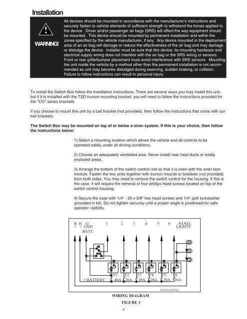
B H G 1 2 3 4 5 6 PANEL<br />
+ + GND LIGHTS<br />
BATT.<br />
F1 F2 F3 F4 F5 F6<br />
+ BATTERY 40A 20A 20A 20A 20A 20A<br />
WIRING DIAGRAM<br />
FIGURE 3<br />
4<br />
BACK LIGHTING