RockerPak™ Model 430 SWITCH CONTROL - Code 3
RockerPak™ Model 430 SWITCH CONTROL - Code 3
RockerPak™ Model 430 SWITCH CONTROL - Code 3

Create successful ePaper yourself
Turn your PDF publications into a flip-book with our unique Google optimized e-Paper software.
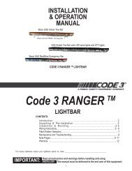
INSTALLATION<br />
& OPERATION<br />
MANUAL<br />
ROCKERPAK <br />
MODEL <strong>430</strong><br />
IMPORTANT:<br />
RockerPak <br />
<strong>Model</strong> <strong>430</strong><br />
<strong>SWITCH</strong> <strong>CONTROL</strong><br />
Contents: Introduction ...................................................................... 2<br />
Safety First ....................................................................... 3<br />
Unpacking & Pre-Installation ................................................ 3<br />
Installation ........................................................................ 4<br />
Wiring ......................................................................... 5<br />
Parts List .......................................................................... 6<br />
Warranty .......................................................................... 8<br />
Read all instructions and warnings before installing and using.<br />
INSTALLER: This manual must be delivered to the end user of this equipment.
Introduction<br />
The Switch Box switch control panel is designed to accommodate six rocker type switches, which are used to<br />
control various vehicle mounted devices. Six legend inserts are installed above the switches as shown in<br />
figure 1 and 2. Six additional legend inserts are included as part of the accessory kit packed with the switch<br />
module.<br />
A thermal lock out type circuit breaker, rated at 40 amps, protects the rotating light circuit (#1). The circuit of<br />
one load current is rated at 40 amps. The other circuits (2 through 6) are protected by automotive blade type<br />
fuses rated at 20 amperes.<br />
The switch module is designed to be installed in a vehicle mounting surface to mate with other devices of the<br />
same width.<br />
It can be installed on top of TSD style panels, trunion mount, and many other types of the same width. It may<br />
be used with various models of electronic sirens with the hardware included in the accessory kit, and secured<br />
to the mounting surface with the bracket included with the electronic siren.<br />
Sizes, ratings and switches: the switches are a rugged unit and rated at 20 amperes @ 12 VDC. The panel's<br />
dimensions are 2 3/16" x 6 1/16" x 5 7/8" (including fuses). Overall weight of the unit is 2 pounds.<br />
!<br />
WARNING!<br />
FIGURE 1<br />
The use of this or any warning device does not insure that all drivers can or will observe or<br />
react to an emergency warning signal. Never take the right-of-way for granted. It is your<br />
responsibility to be sure you can proceed safely before entering an intersection, driving<br />
against traffic, responding at a high rate of speed, or walking on or around traffic lanes.<br />
The effectiveness of this warning device is highly dependent upon correct mounting and<br />
wiring. Read and follow the manufacturer’s instructions before installing or using this<br />
device. The vehicle operator should insure daily that all features of the device operate<br />
correctly. In use, the vehicle operator should insure the projection of the warning signal is<br />
not blocked by vehicle components (i.e.: open trunks or compartment doors), people,<br />
vehicles, or other obstructions.<br />
This equipment is intended for use by authorized personnel only. It is the user’s responsibility<br />
to understand and obey all laws regarding emergency warning devices. The user<br />
should check all applicable city, state and federal laws and regulations.<br />
Public Safety Equipment, Inc., assumes no liability for any loss resulting from the use of this<br />
warning device.<br />
Proper installation is vital to the performance of this warning device and the safe operation<br />
of the emergency vehicle. It is important to recognize that the operator of the emergency<br />
vehicle is under psychological and physiological stress caused by the emergency situation.<br />
The warning device should be installed in such a manner as to: A) Not reduce the output<br />
performance of the system, B) Place the controls within convenient reach of the operator<br />
so that he can operate the system without losing eye contact with the roadway.<br />
Emergency warning devices often require high electrical voltages and/or currents. Properly<br />
protect and use caution around live electrical connections. Grounding or shorting of<br />
electrical connections can cause high current arcing, which can cause personal injury and/<br />
or severe vehicle damage, including fire. Incandescent lamps are extremely hot, allow to<br />
cool completely before attempting to remove.<br />
Any electronic device may create or be affected by electromagnetic interference. After<br />
installation of any electronic device operate all equipment simultaneously to insure that<br />
operation is free of interference. Never power emergency warning equipment from the<br />
same circuit or share the same grounding circuit with radio communication equipment.<br />
PROPER INSTALLATION COMBINED WITH OPERATOR TRAINING IN THE PROPER<br />
USE OF EMERGENCY WARNING DEVICES IS ESSENTIAL TO INSURE THE SAFETY<br />
OF EMERGENCY PERSONNEL AND THE PUBLIC.<br />
2
Safety First<br />
Installers should keep in mind the importance of safe installation to protect the lives of those who may<br />
depend upon this equipment. Please read all instructions supplied with this equipment. Listed below are<br />
some other important safety instructions to follow:<br />
To properly install the equipment described in this instruction sheet: you must have a good<br />
understanding of automotive electrical procedures and systems, along with proficiency in the<br />
installation and use of safety warning equipment.<br />
Locate the switch module so the vehicle and controls can be operated safely under all driving<br />
conditions.<br />
When drilling into a vehicle structure, be sure that both sides of the surface are clear of anything<br />
that could be damaged.<br />
Keep these instructions in a safe place and refer to them when maintaining and/or reinstalling the<br />
product.<br />
Failure to follow all safety precautions and instructions may result in property damage, serious injury, or<br />
death to you or others.<br />
Unpacking & Pre-installation<br />
Carefully remove the Switch Control from the shipping carton and place on a flat surface, taking care not to<br />
damage the wire cable coming out of the back of control box. Examine the unit for transit damage, dented<br />
cover, ect.. If convenient, you may wish to bench test the unit before installing. Before applying voltage to the<br />
bar, be sure you have read and understand the wiring instructions on page 5.<br />
FIGURE 2<br />
3
Installation<br />
!<br />
WARNING!<br />
WARNING!<br />
All devices should be mounted in accordance with the manufacturer's instructions and<br />
securely fasten to vehicle elements of sufficient strength to withstand the forces applied to<br />
the device. Driver and/or passenger air bags (SRS) will affect the way equipment should<br />
be mounted. This device should be mounted by permanent installation and within the<br />
zones specified by the vehicle manufacturer, if any. Any device mounted in the deployment<br />
area of an air bag will damage or reduce the effectiveness of the air bag and may damage<br />
or dislodge the device. Installer must be sure that this device, its mounting hardware and<br />
electrical supply wiring does not interfere with the air bag or the SRS wiring or sensors.<br />
Front or rear grille/bumper placement must avoid interference with SRS sensors. Mounting<br />
the unit inside the vehicle by a method other than the permanent installation is not recommended<br />
as unit may become dislodged during swerving, sudden braking, or collision.<br />
Failure to follow instructions can result in personal injury.<br />
To install the Switch Box follow the installation instructions. There are several ways you may install this unit,<br />
but if it is installed with the TSD trunion mounting bracket, you will need to follow the instructions provided for<br />
the "CO" series brackets.<br />
If you choose to mount this unit by a bail bracket (not provided), then follow the instructions that come with our<br />
bail brackets.<br />
The Switch Box may be mounted on top of or below a siren system. If this is your choice, then follow<br />
the instructions below:<br />
1) Select a mounting location which allows the vehicle and all controls to be<br />
operated safely under all driving conditions.<br />
2) Choose an adequately ventilated area. Never install near heat ducts or totally<br />
enclosed areas.<br />
3) Arrange the bottom of the switch control unit so that it is even with the siren face<br />
module. Fasten the two units together with trunion mounts or brackets (not provided)<br />
from both sides. You may need to remove the switch control for the housing. If this is<br />
the case, it will require the removal of four phillips head screws located on top of the<br />
switch control housing.<br />
4) Secure the case with 1/4" - 20 x 5/8" hex head screws and 1/4" split lockwasher<br />
(provided in kit). Do not tighten securely until a proper angle is positioned for safe<br />
operator visibility.<br />
B H G 1 2 3 4 5 6 PANEL<br />
+ + GND LIGHTS<br />
BATT.<br />
F1 F2 F3 F4 F5 F6<br />
+ BATTERY 40A 20A 20A 20A 20A 20A<br />
WIRING DIAGRAM<br />
FIGURE 3<br />
4<br />
BACK LIGHTING
WARNING!<br />
Wiring<br />
!<br />
WARNING!<br />
5) Tilt the unit to the desired position and tighten the 1/4" - 20 x 3/8" hex head<br />
screws.<br />
6) Use the mounting bracket as a templet and position for two hole by marking the<br />
position with a scribe. Drill holes for positioning the mounting bracket.<br />
CAUTION: When drilling holes in any part of the vehicle, make sure that both sides<br />
of the surface are clear of parts that could be damaged; such as brake lines,<br />
electrical wiring, fuel lines, or other vital parts of the vehicle.<br />
7) Drill two 1/4" diameter holes at the position marked.<br />
8) Secure the mounting bracket in place. Make sure all positions are tight and<br />
screws secured in place.<br />
NOTE: Many other locations may be of better choice for your operation. If other<br />
locations are selected, use every precautionary measure to safely install to prevent<br />
damage to the vehicle.<br />
Larger wires and tight connections will provide longer service life for components. For high<br />
current wires it is highly recommended that terminal blocks or soldered connections be used<br />
with shrink tubing to protect the connections. Do not use insulation displacement connectors<br />
(e.g. 3M ® Scotchlock type connectors). Route wiring using grommets and sealant when<br />
passing through compartment walls. Minimize the number of splices to reduce voltage drop.<br />
High ambient temperatures (e.g. underhood) will significantly reduce the current carrying<br />
capacity of wires, fuses, and circuit breakers. Use "SXL" type wire in engine compartment.<br />
All wiring should conform to the minimum wire size and other recommendations of the<br />
manufacturer and be protected from moving parts and hot surfaces. Looms, grommets,<br />
cable ties, and similar installation hardware should be used to anchor and protect all wiring.<br />
Fuses or circuit breakers should be located as close to the power takeoff points as possible<br />
and properly sized to protect the wiring and devices. Particular attention should be paid to<br />
the location and method of making electrical connections and splices to protect these points<br />
from corrosion and loss of conductivity. Ground terminations should only be made to<br />
substantial chassis components, preferably directly to the vehicle battery. The user should<br />
install a fuse sized to approximately 125% of the maximum Amp capacity in the supply line<br />
to protect against short circuits. For example, a 30 Amp fuse should carry a maximum of 24<br />
Amps. DO NOT USE 1/4" DIAMETER GLASS FUSES AS THEY ARE NOT SUITABLE<br />
FOR CONTINUOUS DUTY IN SIZES ABOVE 15 AMPS. Circuit breakers are very sensitive<br />
to high temperatures and will "false trip" when mounted in hot environments or operated<br />
close to their capacity.<br />
Figure 2 illustrates the correlation of tagged wires to a corresponding operation. Example: Switch one (starting<br />
from left to right) controls the electronic operation of the wire tagged as #1.<br />
Insulated male terminals, which mate with the female terminals on the switch module wiring harness, have<br />
been included in the accessory kit to facilitate installation. These terminals should be installed on the end of<br />
the lead wire which will mate with the wiring harness lead wire. Use yellow terminals for 10-12 AWG wire and<br />
pink terminals for 18-22 AWG wire.<br />
NOTE: When using the insulated terminals, insure that all crimps are secure and that the male/female<br />
terminals slip into each other and not over each other.<br />
5
To properly wire the switch module, see the wiring diagram shown in figure 3 and perform the following<br />
procedures:<br />
1) Use 12 AWG wire and connect leads "1" through "6" to the applicable accessory<br />
load. Remember: lead "1" corresponds to switch "1", lead "2" to switch "2", and so<br />
on.<br />
2) Use 18 AWG wire and connect the ground (earth) lead "G" to a reliable ground<br />
(earth). Each switched device must be grounded with a separate ground (earth) wire.<br />
3) Use 18 AWG wire and connect the backlighting circuit lead "B" to the accessory<br />
terminal of the ignition switch or the vehicle instrument light circuit.<br />
4) Power for the switch module may be obtained from a vehicle power distribution<br />
center (TSD part number D1X1F-PD90) or by a 60, 80, or 100 amp master circuit<br />
breaker (call TSD for part number required). We recommend that all circuits be<br />
protected by fuses or circuit breakers. Installation of a power distribution center or<br />
master circuit breaker should be placed near the battery. Use 8 AWG wire and<br />
connect the power distribution center. If power is obtained in the engine<br />
compartment, a hole will probably have to be drilled into the vehicle firewall. Place a<br />
grommet or similar device in the hole to protect the wire (S) against damage from<br />
rough edges.<br />
CAUTION: When drilling holes in any part of any of the vehicle, ensure that both sides of the surface are clear<br />
of parts that could be damaged: such as brake lines, electrical wiring, fuel lines, or any other vital part of the<br />
vehicle.<br />
Parts List<br />
Description Qty.<br />
1/4" - 20 x 5/8" bolts 2<br />
1/4" lock washer 2<br />
wire ties 2<br />
insulated 1/4" male terminals (yellow) 7<br />
insulated 1/4" male terminals (pink) 2<br />
legend inserts, (TAKE DOWN, GRILLE LIGHTS, DECK LIGHTS, 8<br />
STROBE,AUX., WIGWAG, FRT/REAR FLASHER, (CENTER &<br />
SWEEPS))<br />
6
NOTES<br />
7
WARRANTY<br />
This product was tested and found to be operational at the time of manufacture. Provided this<br />
product is installed and operated in accordance with the manufacturer's recommendations, <strong>Code</strong> 3, Inc.<br />
guarantees all parts and components except the lamps for a period of 1 year from the date of purchase<br />
or delivery, whichever is later. Units demonstrated to be defective within the warranty period will be<br />
repaired or replaced at the factory service center at no cost.<br />
Use of a lamp or other electrical load of a wattage higher than installed or recommended by the<br />
factory, or use of inappropriate or inadequate wiring or circuit protection causes this warranty to become<br />
void. Failure or destruction of the product resulting from abuse or unusual use and/or accidents is<br />
not covered by this warranty.<br />
<strong>Code</strong> 3, Inc. shall in no way be liable for other damages including consequential, indirect or<br />
special damages whether loss is due to negligence or breach of warranty.<br />
CODE 3, INC. MAKES NO OTHER EXPRESS OR IMPLIED WARRANTY INCLUDING, WITH-<br />
OUT LIMITATION, WARRANTIES OF FITNESS OR MERCHANTABILITY, WITH RESPECT TO<br />
THIS PRODUCT.<br />
PRODUCT RETURNS<br />
If a product must be returned for repair or replacement*, please contact our factory to obtain a<br />
Return Goods Authorization Number (RGA number) before you ship the product to <strong>Code</strong> 3, Inc. Write<br />
the RGA number clearly on the package near the mailing label. Be sure you use sufficient packing<br />
materials to avoid damage to the product being returned while in transit.<br />
*<strong>Code</strong> 3, Inc. reserves the right to repair or replace at its discretion. <strong>Code</strong> 3, Inc. assumes no responsibility or liability for expenses incurred for the<br />
removal and /or reinstallation of products requiring service and/or repair.; nor for the packaging, handling, and shipping: nor for the handling of products return to<br />
sender after the service has been rendered.<br />
NEED HELP? Call our Technical Assistance Hotline - (314) 996-2800<br />
RockerPak is a trademark of <strong>Code</strong> 3, Inc. <strong>Code</strong> 3 is a registered trademark of <strong>Code</strong> 3, Inc. a subsidiary of Public Safety Equipment, Inc.<br />
<strong>Code</strong> 3, Inc.<br />
10986 N. Warson Road<br />
St. Louis, Missouri 63114-2029—USA<br />
www.code3pse.com<br />
Revision 4, 02/2006 - Instruction Book Part No. T04922<br />
©2001-6 <strong>Code</strong> 3, Inc. Printed in USA