
Create successful ePaper yourself
Turn your PDF publications into a flip-book with our unique Google optimized e-Paper software.
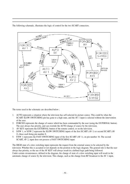
The following schematic, illustrates the logic of control for the two SCART connectors.<br />
The terms used in the schematic are described below ;<br />
1. AUTO represents a situation where the television has self-selected its picture source. This could be when the<br />
SCART SLOW SWITCHING pin has gone to a high state, and the AV 1 input is selected without the intervention<br />
of the user.<br />
2. FORCED represents the change of source which has been commanded by the user (using the EXTERNAL button).<br />
The user always has priority, and can override the AUTO change of source by the television.<br />
3. AV KEY represents the EXTERNAL button of the remote control, or on the television.<br />
4. S/SW 1, or S/SW 2 represent the SLOW SWITCHING inputs of the first SCART (AV 1) or second SCART (AV<br />
2), these each being pin number 8.<br />
5. F/SW 1 represents the FAST SWITCHING input of the first SCART (AV 1), on pin number 16. The second<br />
SCART, AV 2, input does not possess a FAST SWITCHING input.<br />
The HIGH state of a slow switching input represents the request from the external source to be selected by the<br />
television. Whether this is accepted or not depends on the position in the logic diagram. The general rule is that the user<br />
always has priority, so the use of the AV KEY will always result in a defined logic path being followed.<br />
Under certain circumstances, defined in the diagram, the change of state of a slow switching input will result in the<br />
automatic change of source by the television. This change, such as the change from RF broadcast to the AV 1 input,<br />
- 50 -