200 series optimount® dimensions - Boston Gear
200 series optimount® dimensions - Boston Gear
200 series optimount® dimensions - Boston Gear

Create successful ePaper yourself
Turn your PDF publications into a flip-book with our unique Google optimized e-Paper software.
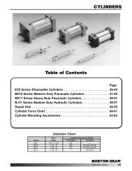
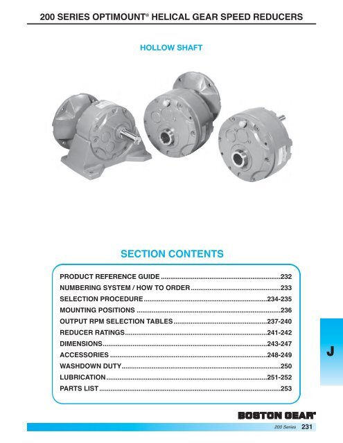
<strong>200</strong> SERIES OPTIMOUNT ® HELICAL GEAR SPEED REDUCERS<br />
HOLLOW SHAFT<br />
SECTION CONTENTS<br />
PRODUCT REFERENCE GUIDE ................................................................232<br />
NUMBERING SYSTEM / HOW TO ORDER ................................................233<br />
SELECTION PROCEDURE..................................................................234-235<br />
MOUNTING POSITIONS .............................................................................236<br />
OUTPUT RPM SELECTION TABLES ..................................................237-240<br />
REDUCER RATINGS............................................................................241-242<br />
DIMENSIONS........................................................................................243-247<br />
ACCESSORIES ....................................................................................248-249<br />
WASHDOWN DUTY.....................................................................................250<br />
LUBRICATION......................................................................................251-252<br />
PARTS LIST.................................................................................................253<br />
<strong>200</strong> Series<br />
231<br />
J
J<br />
232 <strong>200</strong> Series<br />
<strong>200</strong> SERIES OPTIMOUNT ® PRODUCT REFERENCE GUIDE<br />
Ordering Information – Pages 233-235<br />
Selection/Rating Information – Pages 237-240<br />
Lubrication – Pages 251-252<br />
Motor Selection – Pages 324, 327-331<br />
F<strong>200</strong> Series Optimount ® Helical <strong>Gear</strong><br />
Flanged Reducers<br />
Basic Model F<strong>200</strong>H Series F<strong>200</strong>V Series<br />
Horizontal Base Model Vertical Base Model<br />
Dimensions – Page 243 Dimensions – Page 244 Dimensions – Page 244<br />
Ordering Information – Pages 233-235<br />
Selection/Rating Information – Pages 241-242<br />
Lubrication – Pages 251-252<br />
Motor Selection – Pages 322, 325-329<br />
<strong>200</strong> Series Optimount ® Helical <strong>Gear</strong><br />
Non-Flanged Reducers<br />
Basic Model <strong>200</strong>H Series <strong>200</strong>V Series<br />
Horizontal Base Model Vertical Base Model<br />
Dimensions – Pages 245 & 247 Dimensions – Page 246 Dimensions – Page 246<br />
Ordering Information – Pages 233<br />
<strong>200</strong> Series Optimount ® Helical <strong>Gear</strong><br />
Accessories and Options<br />
Shaft Kits / Reaction Rods Base Kits<br />
Vertical/Horizontal<br />
Dimensions – Page 248 Dimensions – Page 249
<strong>200</strong> SERIES OPTIMOUNT ® NUMBERING SYSTEM/HOW TO ORDER<br />
CATALOG NUMBERING SYSTEM<br />
When ordering please note the complete catalog number and/or the (5-digit) item code. With either of these two<br />
numbers your local <strong>Boston</strong> Distributor will have several alternatives to enter your order into the <strong>Boston</strong> <strong>Gear</strong> system.<br />
BK F 2 31 D P H 14 B9 H1 1<br />
OPTIONAL WASHDOWN SERIES<br />
BK-Bost-Kleen (white)<br />
OPTIONAL INPUT STYLE<br />
FLANGED REDUCER<br />
F - QUILL TYPE<br />
PROJECTING SHAFT<br />
“BLANK”<br />
SERIES<br />
<strong>200</strong> Series<br />
REDUCER SIZE<br />
Center Dist.<br />
21 2.12<br />
26 2.60<br />
31 3.11<br />
39 3.89<br />
47 4.67<br />
NUMBER OF REDUCTIONS<br />
S - SINGLE<br />
D- DOUBLE<br />
OPTIONAL OUTPUT SHAFT*<br />
P – Removable<br />
Projection Shaft<br />
“BLANK” – Hollow Only SPECIAL NOTE: All reducers are shipped without oil.<br />
HOW TO ORDER: Specify Model Number (Basic Hollow Output Shaft Reducer), Ratio, Input Bore Code,<br />
Horizontal or Vertical Base Kit and Output Shaft Kit.<br />
Example: F239DPH-14-B9**<br />
Order – 1 Pc. F239D-14-B9 (Basic Flanged Reducer) (39272)<br />
1 Pc. X239-3PK (Output Shaft Kit) (23904)<br />
1 Pc. X239-11HK (Horizontal Base Kit) (68658)<br />
*Shipped separately unless otherwise specified.<br />
**If components are to be factory assembled, specify Assembly Type and Mounting Position, see Page 236<br />
MOUNTING POSITION<br />
1 (standard) 4<br />
2 5<br />
3 6<br />
**See note below.<br />
ASSEMBLY TYPE<br />
H1 V1 (standard)<br />
H2 V2<br />
H3 V3<br />
H4 V4<br />
**See note below.<br />
OPTIONAL NEMA MOTOR<br />
FRAME SIZE<br />
INPUT<br />
CODE NEMA MTG<br />
BORE SIZE<br />
B5 .625 56C<br />
B7 .875 140TC/180C<br />
B9 1.125 180TC/210C<br />
B11 1.375 210TC/250UC<br />
NOMINAL GEAR RATIO<br />
Refer to Selection Tables<br />
for Available Ratios<br />
OPTIONAL BASE*<br />
H – Horizontal<br />
V – Vertical<br />
BLANK – None<br />
<strong>200</strong> Series<br />
233<br />
J
J<br />
<strong>200</strong> SERIES OPTIMOUNT ® HELICAL GEAR SPEED REDUCERS<br />
To properly select a speed reducer, the following<br />
application information should be known.<br />
1. Service Factor or AGMA Service class.<br />
2. Output Horsepower or Torque<br />
3. Output RPM or Ratio<br />
Non-Motorized Speed Reducer<br />
1. Determine application service factor from table 1<br />
or from application classification tables on pages<br />
340 & 341.<br />
2. Determine design Horsepower or Torque.<br />
– Design HP = Application HP x S.F.<br />
– Design Torque = Application Torque x S.F.<br />
3. Select a Speed reducer that satisfies output RPM,<br />
service class and/or output torque requirement.<br />
Ref. rating tables pages 241-242.<br />
4. Overhung shaft load should be checked when belt<br />
or chain drives are used, to prevent premature<br />
shaft or bearing failure. Reference page 235 for<br />
calculations.<br />
EXAMPLE<br />
Select a parallel shaft helical speed reducer for a<br />
uniformly loaded assembly belt conveyor to operate 12<br />
hrs/day to be driven at 1150 RPM input. Output RPM<br />
Approx. 80, Torque requirement is 2<strong>200</strong> lb-in.<br />
1. Application Service Factor = 1.25<br />
2. Design Torque = 2<strong>200</strong> x 1.25<br />
= 2750 LB-IN.<br />
3. Select at speed and torque level of at least 2750<br />
LB-IN or greater<br />
4. Order 239D-14<br />
(Item Code 39052)<br />
234 <strong>200</strong> Series<br />
NOTE: The use of an auxiliary drive between the<br />
speed reducer and the driven machine reduces the<br />
torque required at the output shaft in direct proportion<br />
to the auxiliary drive ratio.<br />
A 3:1 chain ratio would reduce the torque<br />
requirement at the output shaft of the reducer to onethird,<br />
resulting in a smaller unit size selection.<br />
SERVICE FACTOR TABLE<br />
AGMA<br />
CLASS OF SERVICE<br />
SERVICE FACTOR OPERATING CONDITIONS<br />
Moderate Shock-not more than 15<br />
I 1.00<br />
II<br />
III<br />
1.25<br />
1.50<br />
1.75<br />
2.00<br />
minutes in 2 hours.<br />
Uniform Load-not more than 10<br />
hours per day.<br />
Moderate Shock-not more than 10<br />
hours per day.<br />
Uniform Load-more than 10 hours<br />
per day.<br />
Heavy Shock-not more than 15<br />
minutes in 2 hours.<br />
Moderate Shock-more than 10<br />
hours per day.<br />
Heavy Shock-not more than 10<br />
hours per day.<br />
Heavy Shock-more than 10 hours<br />
per day.<br />
For complete AGMA Service Factors and Load Classifications, see<br />
Engineering Pages 340 and 341.<br />
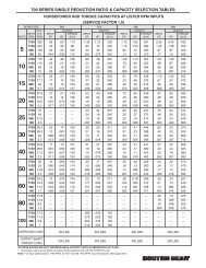
<strong>200</strong> SERIES RATIO AND CAPACITY SELECTION TABLES<br />
(SERVICE FACTOR 1.0)<br />
1750 1150<br />
Output HP Output HP<br />
Catalog Item Torque Torque <strong>Gear</strong> O.H.L. Wt<br />
Number Code RPM (LB.-IN.) Input Output RPM (LB.-IN.) Input Output Ratio (LB.)* Lb.<br />
221D-14 39004 403 0.80 0.77 403 0.53 0.51 490 23<br />
226D-14 39020 711 1.43 1.37 772 1.02 0.97 660 38<br />
231D-14 39036 121 1488 2.98 2.86 80 1781 2.34 2.25 14.45 780 57<br />
239D-14 39052 2842 5.69 5.46 3168 4.17 4.00 875 96<br />
247D-14 39068 4736 9.48 9.10 5662 7.45 7.15 1070 140<br />
221D-17 39006 410 0.69 0.66 410 0.45 0.43 500 23<br />
226D-17 39022 754 1.26 1.21 805 0.89 0.85 675 38<br />
231D-17 39038 101 1644 2.75 2.64 67 1857 2.04 1.96 17.28 800 57<br />
239D-17 39054 2959 4.96 4.75 3219 3.54 3.40 900 96<br />
247D-17 39070 5071 8.49 8.15 5775 6.34 6.10 1100 135<br />
Ref. Page 241
<strong>200</strong> SERIES OPTIMOUNT ® HELICAL GEAR SPEED REDUCERS<br />
MOTORIZED SPEED REDUCER<br />
1. Determine application service factor from the table<br />
on page 234 or from pages 340 and 341.<br />
2. Determine output speed required.<br />
3. Determine HP or output torque requirement.<br />
4. Select based on output speed and horsepower<br />
requirement for given service class.<br />
5. Check overhung load Ref. calculation.<br />
EXAMPLE<br />
Select a Parallel Shaft Helical <strong>Gear</strong> Flanged Speed<br />
Reducer and motor to drive a uniformly loaded line<br />
shaft 12 hours/day, requiring approximately 1 1/2 HP<br />
at 100 RPM.<br />
Power Requirement<br />
230/460 volt<br />
3 phase<br />
60 Hz<br />
1. Select service factor class from pages 340 and 341<br />
or from Table 1.<br />
Service class = II<br />
2. Output RPM = 100<br />
3. 1 1/2 HP<br />
4. Select a 1 1/2 HP drive that will satisfy service<br />
class II.<br />
5. O.H.L = 800 LBS. Ref. pg. 241<br />
6. Order:1 – F231D-17-B7 (39250)<br />
1 – JUTF Motor Ref. page 327 for specific<br />
manufacturer.<br />
OVERHUNG LOAD<br />
If the output shaft of a speed reducer is connected to<br />
the driven machine by other than a flexible coupling, an<br />
overhung load is imposed on the shaft. This load may<br />
be calculated as follows:<br />
OHL = 2 TK<br />
D<br />
<strong>200</strong> SERIES OUTPUT RPM AND CAPACITY SELECTION TABLES<br />
OHL = Overhung Load (LB.)<br />
T = Shaft Torque (LB.-INS.)<br />
D = PD of Sprocket, Pinion or Pulley (IN.)<br />
K = Load Connection Factor<br />
LOAD CONNECTION FACTOR (K)<br />
Sprocket or Timing Belt ................................ 1.00<br />
Pinion and <strong>Gear</strong> Drive .................................. 1.25<br />
Pulley and V-Belt Drive................................. 1.50<br />
Pulley and Flat Belt Drive ............................. 2.50<br />
An overhung load greater than permissible load value<br />
may be reduced to an acceptable value by the use of a<br />
sprocket, pinion or pulley of a larger PD. Relocation of<br />
the load closer to the center of reducer will also<br />
increase OHL capacity.<br />
Permissible Overhung Loads and Output Shaft Thrust<br />
Loads are listed for each reducer in the Tables on<br />
Pages 241-242.<br />
@ 1750 RPM INPUT<br />
NON-FLANGED REDUCERS FLANGED REDUCERS (GEARMOTORS)<br />
OUT- GEAR CAPACITY RATING<br />
PUT<br />
RPM RATIO OUTPUT HP CATALOG ITEM OUTPUT SERV- CATALOG ITEM AC DC<br />
TORQUE OUT- NUMBER CODE MOTOR TORQUE ICE NUMBER CODE MOTORS † MOTORS ††<br />
(LB.IN.) INPUT PUT HP CLASS<br />
101 17.28 1644 2.75 2.64 231D-17 39038 2 1194 I F231D-17-B7 39250 KUTF PM18<strong>200</strong><br />
Cont.<br />
1 1/2 896 II JUTF PM18150<br />
1 597 III F231D-17-B5 39246 HUTF-5/8 PM9100 5/8<br />
PM18100 5/8<br />
2959 4.96 4.76 239D-17 39054 5 2986 I F239D-17-B9 39276 MUTF PM18500<br />
Reference Page 239<br />
<strong>200</strong> Series<br />
235<br />
J
J<br />
236 <strong>200</strong> Series<br />
<strong>200</strong> SERIES OPTIMOUNT ® MOUNTING POSITIONS<br />
<strong>200</strong> SERIES—HORIZONTAL BASE<br />
4<br />
ASSEMBLY TYPES<br />
H1 H2<br />
H3 H4<br />
MOUNTING POSITIONS<br />
WALL<br />
3<br />
FLOOR<br />
CEILING<br />
NOTE: Shaded positions are not recommended<br />
when used as a motorized reducer and should be<br />
avoided if possible.<br />
Mountings are designated by combining identification<br />
for assembly type and mounting position (Example<br />
Mtg. H11).<br />
Mounting H11 is standard and will be furnished<br />
unless otherwise specified.<br />
SIZES 221 TO 247<br />
All other assemblies are available at no additional<br />
charge. The assembly types shown indicate the four<br />
possible arrangements of the Reductor in the base.<br />
Any of these assemblies may be installed in the various<br />
floor sidewall or ceiling mounting positions shown by<br />
relocating oil plugs in proper positions. Reference<br />
pages 251-252.<br />
CAUTION<br />
Mounting of speed reducers in overhead positions<br />
may be hazardous. Use of external guides or<br />
supports is strongly recommended for overhead<br />
mounting.<br />
1<br />
WALL<br />
MOTOR UP MOTOR DOWN<br />
5<br />
6<br />
2<br />
<strong>200</strong> SERIES—VERTICAL BASE<br />
Mountings are designated by combining identification<br />
for assembly type and mounting position (Example<br />
Mtg. V11).<br />
Mounting V11 is standard and will be furnished unless<br />
otherwise specified. All other mountings are available<br />
at no additional charge.<br />
SIZES 221 TO 247<br />
Assemblies V1 & V2 may be installed in the various<br />
floor, side-wall or ceiling mounting positions shown.<br />
Sidewall Mounted Reducers must be located with one<br />
edge of the base parallel to the floor so that oil plugs<br />
can be properly located.<br />
Mounting designations other than standard must be<br />
included with each Reductor order.<br />
<strong>200</strong> SERIES<br />
FLOOR<br />
S1<br />
ASSEMBLY TYPES<br />
V1<br />
V2<br />
MOUNTING POSITIONS<br />
W<br />
A<br />
L<br />
CEILING<br />
FLOOR L<br />
1<br />
2<br />
3<br />
SHAFT MOUNTING<br />
MOUNTING POSITIONS<br />
W<br />
A<br />
L<br />
L<br />
Mounting S2 is standard and will be furnished unless<br />
otherwise specified. Mountings S1 & S3 are available at<br />
a slight additional charge.<br />
SIZES 221 TO 247<br />
CEILING<br />
S2 S3<br />
Shaft Mounted Reductors may be installed in floor,<br />
sidewall or ceiling mounting positions by proper<br />
relocation of oil plugs. Reference to pages 251-252.
<strong>200</strong> SERIES OUTPUT RPM AND CAPACITY SELECTION TABLES @1750 RPM INPUT<br />
FOR RATINGS AT OTHER INPUT SPEEDS, SEE TABLES ON PAGES 241-242<br />
ORDER BY CATALOG NUMBER OR ITEM CODE<br />
Non-Flanged Reducers Flanged Reducers (<strong>Gear</strong>motors)<br />
<strong>Gear</strong> Capacity Ratings<br />
Output Ratio Output Output<br />
RPM * Torque HP Catalog Item Motor Torque Torque Service Catalog Item AC DC DC<br />
(LB-IN.) Input Output Number Code HP (LB-IN.) Class Number Code Motors† Motors††<br />
289 2.02 1.98 221S-4 39012 1 142 III F221S-4-B5 39214 HUTF-5/8 PM9100 5/8<br />
PM18100 5/8<br />
3/4 106 III GUTF PM975<br />
455 3.17 3.11 226S-4 39028 2 284 II F226S-4-B7 39236 KUTF PM18<strong>200</strong><br />
1 1/2 213 III JUTF PM18150<br />
950 6.63 6.50 231S-4 39044 5 716 I F231S-4-B9 39264 MUTF PM18500<br />
431 4.06 3 423 III LUTF PM18300<br />
1900 13.26 12.99 239S-4 39060 10 1432 I F239S-4-B11 39290 PUTF —<br />
7 1/2 1074 II NUTF —<br />
5 716 III F239S-4-B9 39288 MUTF PM18500<br />
2851 19.90 19.50 247S-4 39076 10 1432 II F247S-4-B11 39308 PUTF —<br />
7 1/2 1074 III NUTF —<br />
390 1.15 1.10 221D-10 39002 1 340 I F221D-10-B5 39202 HUTF-5/8 PM9100 5/8<br />
PM18100 5/8<br />
3/4 255 II GUTF PM975<br />
1/2 170 III FUTF PM950<br />
672 2.00 1.90 226D-10 39018 2 660 I F226D-10-B7 39220 KUTF PM18<strong>200</strong><br />
1 1/2 510 I JUTF PM18150<br />
1 340 II F226D-10-B5 39218 HUTF-5/8 PM9100 5/8<br />
PM18100 5/8<br />
178 9.84 3/4 255 III GUTF PM975<br />
PM1875<br />
1322 3.89 3.73 231D-10 39034 3 1020 I F231D-10-B9 39242 LUTF PM18300<br />
2 680 II F231D-10-B7 39240 KUTF PM18<strong>200</strong><br />
1 1/2 510 III JUTF PM18150<br />
2426 7.12 6.84 239D-10 39050 5 1700 I F239D-10-B9 39268 MUTF PM18500<br />
3 1020 III LUTF PM18300<br />
Class I (S.F. = 1.00) Class II (S.F. = 1.50) Class III (S.F. = 2.00)<br />
† AC Motors – 230/460-3-60 TEFC, for specific motor manufacturers and 5 digit item code refer to pages 327-329.<br />
†† DC Motors – 90 VDC or 180 VDC where applicable, for specific motor manufacturers and 5 digit item code ref. pages 330 and 331.<br />
<strong>200</strong> Series<br />
237<br />
J
J<br />
<strong>200</strong> SERIES OUTPUT RPM AND CAPACITY SELECTION TABLES @1750 RPM INPUT<br />
238 <strong>200</strong> Series<br />
FOR RATINGS AT OTHER INPUT SPEEDS, SEE TABLES ON PAGES 241-242<br />
ORDER BY CATALOG NUMBER OR ITEM CODE<br />
Non-Flanged Reducers Flanged Reducers (<strong>Gear</strong>motors)<br />
<strong>Gear</strong> Capacity Ratings<br />
Output Ratio Output Output<br />
RPM Torque HP Catalog Item Motor Torque Service Catalog Item AC DC<br />
(LB-IN.) Input Output Number Code HP (LB-IN.) Class Number Code Motors† Motors††<br />
4641 13.64 13.09 247D-10 39066 10 3400 I F247D-10-B11 39296 PUTF —<br />
178 9.84 7 1/2 2550 II NUTF —<br />
(CONT.) 5 1700 III F247D-10-B9 39294 MUTF PM18500<br />
403 .80 .77 221D-14 39004 3/4 374 I F221D-14-B5 39204 GUTF PM975<br />
1/2 250 II FUTF PM950<br />
1/3 166 III EUTF PM933<br />
711 1.43 1.37 226D-14 39020 1 1/2 *711 * F226D-14-B7 39224 JUTF PM18150<br />
1 500 I F226D-14-B5 39222 HUTF-5/8 PM9100 5/8<br />
PM18100 5/8<br />
3/4 374 II GUTF PM975<br />
1/2 250 III FUTF PM950<br />
1500 3.00 2.88 231D-14 39036 3 1500 I F231D-14-B9 47226 LUTF PM18300<br />
2 998 II F231D-14-B7 39248 KUTF PM18<strong>200</strong><br />
121 14.45 1 1/2 750 III JUTF PM18150<br />
1 500 III F231D-14-B5 39244 HUTF-5/8 PM9100 5/8<br />
PM18100 5/8<br />
2842 5.69 5.46 239D-14 39052 5 2497 I F239D-14-B9 39272 MUTF PM18500<br />
3 1498 II LUTF PM18300<br />
2 998 III F239D-14-B7 39270 KUTF PM18<strong>200</strong><br />
4736 9.48 9.10 247D-14 39068 10 *4736 * F247D-14-B11 47232 PUTF —<br />
7 1/2 3745 I NUTF —<br />
5 2497 II MUTF PM18500<br />
3 1498 III F247D-14-B9 39298 LUTF PM18300<br />
410 .69 .66 221D-17 39006 3/4 *410 * F221D-17-B5 39206 GUTF PM975<br />
1/2 298 I FUTF PM950<br />
1/3 199 III EUTF PM933<br />
101 17.28 754 1.26 1.21 226D-17 39022 1 1/2 *754 * F226D-17-B7 47220 JUTF PM18150<br />
1 597 I F226D-17-B5 39226 HUTF-5/8 PM9100 5/8<br />
PM18100 5/8<br />
3/4 448 II GUTF PM975<br />
1/2 298 III FUTF PM950<br />
Class I (S.F. = 1.00) Class II (S.F. = 1.50) Class III (S.F. = 2.00)<br />
† AC Motors – 230/460-3-60 TEFC, for specific motor manufacturers and 5 digit item code refer to pages 327-329.<br />
†† DC Motors – 90 VDC or 180 VDC where applicable, for specific motor manufacturers and 5 digit item code ref. pages 330-331.<br />
*Rating Limited to <strong>Gear</strong> Capacity.
<strong>200</strong> SERIES OUTPUT RPM AND CAPACITY SELECTION TABLES @1750 RPM INPUT<br />
FOR RATINGS AT OTHER INPUT SPEEDS, SEE TABLES ON PAGES 241-242<br />
ORDER BY CATALOG NUMBER OR ITEM CODE<br />
Non-Flanged Reducers Flanged Reducers (<strong>Gear</strong>motors)<br />
<strong>Gear</strong> Capacity Ratings<br />
Output Ratio Output Output<br />
RPM Torque HP Catalog Item Motor Torque Service Catalog Item AC DC<br />
(LB-IN.) Input Output Number Code HP (LB-IN.) Class Number Code Motors† Motors††<br />
1644 2.75 2.64 231D-17 39038 3 *1644 * F231D-17-B9 47227 LUTF PM18300<br />
2 1194 I F231D-17-B7 39250 KUTF PM18<strong>200</strong><br />
1 1/2 896 II JUTF PM18150<br />
1 597 III F231D-17-B5 39246 HUTF-5/8 PM9100 5/8<br />
Class I (S.F. = 1.00) Class II (S.F. = 1.50) Class III (S.F. = 2.00)<br />
† AC Motors – 230/460-3-60 TEFC, for specific motor manufacturers and 5 digit item code refer to pages 327-329.<br />
†† DC Motors – 90 VDC or 180 VDC where applicable, for specific motor manufacturers and 5 digit item code ref. pages 330-331.<br />
*Rating Limited to <strong>Gear</strong> Capacity.<br />
<strong>200</strong> Series<br />
PM18100 5/8<br />
101 2959 4.96 4.76 239D-17 39054 5 *2956 * F239D-17-B9 39276 MUTF PM18500<br />
(CONT.) 17.28 3 1498 II LUTF PM18300<br />
2 1194 III F239D-17-B7 39274 KUTF PM18<strong>200</strong><br />
5071 8.49 8.15 247D-17 39070 7 1/2 4478 I F247D-17-B11 47233 NUTF —<br />
5 2986 II F247D-17-B9 39300 MUTF PM18500<br />
3 1791 III LUTF PM18300<br />
398 .57 .55 221D-20 39008 1/2 346 I F221D-20-B5 39208 FUTF PM950<br />
1/3 230 II EUTF PM933<br />
1/4 173 III DUTF PM925<br />
758 1.09 1.05 226D-20 39024 1 692 I F226D-20-B5 39228 HUTF-5/8 PM9100 5/8<br />
PM18100 5/8<br />
3/4 519 II GUTF PM975<br />
1/2 346 III FUTF PM950<br />
1679 2.43 2.33 231D-20 39040 3 *1679 * F231D-20-B9 47228 LUTF PM18300<br />
87.4 20.03 2 1384 I F231D-20-B7 39254 KUTF PM18<strong>200</strong><br />
1 1/2 1038 II JUTF PM18150<br />
1 692 III F231D-20-B5 39252 HUTF-5/8 PM9100 5/8<br />
PM18100 5/8<br />
3022 4.36 4.19 239D-20 39056 5 *3022 * F239D-20-B9 39280 MUTF PM18500<br />
3 2076 I LUTF PM18300<br />
2 1384 III F239D-20-B7 39278 KUTF PM18<strong>200</strong><br />
5198 7.51 7.21 247D-20 39072 7 1/2 5192 I F247D-20-B11 47234 NUTF —<br />
5 3461 II F247D-20-B9 39302 MUTF PM18500<br />
3 2076 III LUTF PM18300<br />
239<br />
J
J<br />
<strong>200</strong> SERIES OUTPUT RPM AND CAPACITY SELECTION TABLES @1750 RPM INPUT<br />
240 <strong>200</strong> Series<br />
FOR RATINGS AT OTHER INPUT SPEEDS, SEE TABLES ON PAGES 241-242<br />
ORDER BY CATALOG NUMBER OR ITEM CODE<br />
Non-Flanged Reducers Flanged Reducers (<strong>Gear</strong>motors)<br />
<strong>Gear</strong> Capacity Ratings<br />
Output Ratio Output Output<br />
RPM Torque HP Catalog Item Motor Torque Service Catalog Item AC DC<br />
(LB-IN.) Input Output Number Code HP (LB-IN.) Class Number Code Motors† Motors††<br />
414 .50 .48 221D-24 39010 1/2 414 I F221D-24-B5 39210 FUTF PM950<br />
1/3 275 I EUTF PM933<br />
1/4 206 III DUTF PM925<br />
809 .98 .94 226D-24 39026 1 809 I F226D-24-B5 39230 HUTF-5/8 PM9100 5/8<br />
PM18100 5/8<br />
3/4 620 II GUTF PM975<br />
1/2 414 III FUTF PM950<br />
1791 2.17 2.08 231D-24 39042 2 1655 I F231D-24-B7 39258 KUTF PM18<strong>200</strong><br />
73 23.95 1 1/2 1242 II JUTF PM18150<br />
1 828 III F231D-24-B5 39256 HUTF-5/8 PM9100 5/8<br />
PM18100 5/8<br />
3175 3.83 3.68 239D-24 39058 5 *3175 * F239D-24-B9 39284 MUTF PM18500<br />
3 2483 I LUTF PM18300<br />
2 1655 II F239D-24-B7 39282 KUTF PM18<strong>200</strong><br />
1 1/2 1241 III JUTF PM18150<br />
5478 6.61 6.35 247D-24 39074 7 1/2 *5478 * F247D-24-B11 47235 NUTF —<br />
5 4138 I F247D-24-B9 39304 MUTF PM18500<br />
3 2483 III LUTF PM18300<br />
Class I (S.F. = 1.00) Class II (S.F. = 1.50) Class III (S.F. = 2.00)<br />
† AC Motors – 230/460-3-60 TEFC, for specific motor manufacturers and 5 digit item code refer to pages 327-329.<br />
†† DC Motors – 90 VDC or 180 VDC where applicable, for specific motor manufacturers and 5 digit item code ref. pages 330-331.<br />
* Rating Limited to <strong>Gear</strong> Capacity.
<strong>200</strong> SERIES RATIO AND CAPACITY SELECTION TABLES<br />
NON-FLANGED REDUCERS<br />
INPUT SPEEDS 1750 RPM & 1150 RPM Service Factor 1.0<br />
ORDER BY CATALOG NUMBER OR ITEM CODE<br />
INPUT RPM<br />
Catalog Item 1750 1150 <strong>Gear</strong> O.H.L. Wt<br />
Number Code Output HP Output HP Ratio (LB.)* Lb.<br />
O/P<br />
RPM<br />
Torque<br />
(LB-IN) Input Output<br />
O/P<br />
RPM<br />
Torque<br />
(LB-IN) Input Output<br />
221S-4 39012 289 2.02 1.98 300 1.38 1.35 350 25<br />
226S-4 39028 455 3.17 3.11 552 2.53 2.48 475 40<br />
231S-4 39044 431 959 6.63 6.56 283 1144 5.24 5.14 4.06 575 58<br />
239S-4 39060 1900 13.26 12.99 2545 11.67 11.44 650 96<br />
247S-4 39076 2851 19.90 19.50 3557 16.32 15.99 800 137<br />
221D-10 39002 390 1.15 1.10 404 0.78 0.75 460 23<br />
226D-10 39018 672 2.90 1.90 723 1.40 1.34 615 38<br />
231D-10 39034 178 1322 3.89 3.73 117 1581 3.05 2.93 9.84 720 60<br />
239D-10 39050 2426 7.12 6.85 2860 5.52 5.30 800 99<br />
247D-10 39066 4641 13.64 13.10 5071 9.79 9.40 980 140<br />
221D-14 39004 403 0.80 0.77 403 0.53 0.51 490 23<br />
226D-14 39020 711 1.43 1.37 772 1.02 0.97 660 38<br />
231D-14 39036 121 1500 3.00 2.88 80 1781 2.34 2.25 14.45 780 57<br />
239D-14 39052 2842 5.69 5.46 3168 4.17 4.00 875 96<br />
247D-14 39068 4736 9.48 9.10 5662 7.45 7.15 1070 140<br />
221D-17 39006 410 0.69 0.66 410 0.45 0.43 500 23<br />
226D-17 39022 754 1.26 1.21 805 0.89 0.85 675 38<br />
231D-17 39038 101 1644 2.75 2.64 67 1857 2.04 1.96 17.28 800 57<br />
239D-17 39054 2959 5.00 4.80 3219 3.54 3.40 900 96<br />
247D-17 39070 5071 8.49 8.15 5775 6.34 6.10 1100 135<br />
221D-20 39008 398 0.57 0.55 411 0.39 0.37 510 23<br />
226D-20 39024 758 1.09 1.05 838 0.79 0.76 695 38<br />
231D-20 39040 87 1679 2.43 2.33 57 1916 1.81 1.75 20.03 825 57<br />
239D-20 39056 3022 4.36 4.19 3299 3.12 3.01 925 96<br />
247D-20 39072 5198 7.51 7.21 5862 5.56 5.34 1125 135<br />
221D-24 39010 414 0.50 0.48 404 0.31 0.31 525 23<br />
226D-24 39026 809 0.98 0.94 819 0.65 0.62 715 38<br />
231D-24 39042 73 1791 2.17 2.08 48 1886 1.50 1.44 23.95 850 57<br />
239D-24 39058 3175 3.83 3.68 3353 2.66 2.55 950 96<br />
247D-24 39074 5478 6.61 6.35 5760 4.57 4.39 1150 135<br />
* Overhung Load (O.H.L.) in (LB's) is at center of Output Shaft Extension and with no Thrust Load.<br />
Input Shaft<br />
Shaft<br />
Dia.<br />
Allowable Overhung Load in Lbs.<br />
(No Thrust) at 1 and 2<br />
Shaft diameters from Oil Seal<br />
Size (Ins.) 1 2<br />
Output Shaft<br />
Allowable Thrust Load<br />
In Lbs. (No Overhung Load)<br />
221 1/2 80 60 700<br />
226 5/8 100 80 1000<br />
231 15/16 160 120 1100<br />
239 1-3/8 325 225 1<strong>200</strong><br />
247 1-9/16 400 300 1300<br />
<strong>200</strong> Series<br />
241<br />
J
J<br />
242 <strong>200</strong> Series<br />
<strong>200</strong> SERIES RATIO AND CAPACITY SELECTION TABLES<br />
NON-FLANGED REDUCERS<br />
INPUT SPEEDS 690 RPM & 100 RPM Service Factor 1.0<br />
ORDER BY CATALOG NUMBER OR ITEM CODE<br />
INPUT RPM<br />
Catalog Item 690 100 <strong>Gear</strong> O.H.L. Wt<br />
Number Code Output HP Output HP Ratio (LB.)* Lb.<br />
O/P Torque O/P Torque<br />
RPM (LB-IN) Input Output RPM (LB-IN) Input Output<br />
221S-4 39012 313 .86 0.84 343 0.14 0.13 465 25<br />
226S-4 39028 624 1.71 1.68 682 0.28 0.27 620 40<br />
231S-4 39044 170 1275 3.51 3.44 25 1417 0.56 0.55 4.06 730 58<br />
239S-4 39060 2795 7.69 7.54 3113 1.24 1.22 810 96<br />
247S-4 39076 4045 11.14 10.91 4670 1.86 1.83 995 137<br />
221D-10 39002 405 .47 0.45 426 0.07 0.07 530 23<br />
226D-10 39018 798 .93 0.89 985 0.17 0.16 720 38<br />
231D-10 39034 70 1834 2.12 2.04 10 2140 0.36 0.35 9.84 860 60<br />
239D-10 39050 3202 3.71 3.56 3624 0.61 0.58 860 99<br />
247D-10 39066 5605 6.49 6.24 6012 1.01 0.97 1160 140<br />
221D-14 39004 413 .32 0.31 431 0.50 0.05 550 23<br />
226D-14 39020 821 .65 0.62 1051 0.13 0.12 750 38<br />
231D-14 39036 48 1898 1.50 1.44 7 2148 0.25 0.24 14.45 900 57<br />
239D-14 39052 3360 2.66 2.55 3780 0.43 0.42 1000 96<br />
247D-14 39068 5868 4.64 4.45 6060 0.69 0.67 1<strong>200</strong> 140<br />
221D-17 39006 403 .27 0.26 432 0.04 0.04 550 23<br />
226D-17 39022 834 .56 0.53 1068 0.10 0.10 750 38<br />
231D-17 39038 40 1986 1.30 1.26 6 2153 0.21 0.20 17.28 900 57<br />
239D-17 39054 3421 2.26 2.17 3790 0.36 0.35 1000 96<br />
247D-17 39070 5904 3.90 3.74 6076 0.58 0.56 1<strong>200</strong> 135<br />
221D-20 39008 406 .23 0.22 434 0.03 0.03 550 23<br />
226D-20 39024 878 .50 0.48 1072 0.09 0.08 750 38<br />
231D-20 39040 34 <strong>200</strong>5 1.14 1.10 5 2158 0.18 0.17 20.03 900 57<br />
239D-20 39056 3446 1.96 1.88 3800 0.31 0.30 1000 96<br />
247D-20 39072 5958 3.39 3.26 6094 0.50 0.48 1<strong>200</strong> 135<br />
221D-24 39010 409 .20 0.19 436 0.03 0.03 550 23<br />
226D-24 39026 893 .43 0.41 1080 0.08 0.07 750 38<br />
231D-24 39042 29 2046 .97 0.94 4 2162 0.15 0.14 23.95 900 57<br />
239D-24 39058 3492 1.67 1.60 3811 0.26 0.25 1000 96<br />
247D-24 39074 5988 2.85 2.74 6109 0.43 0.40 1<strong>200</strong> 135<br />
* Overhung Load (O.H.L.) in (LB's) is at center of Output Shaft Extension and with no Thrust Load.<br />
Shaft<br />
Dia.<br />
Input Shaft<br />
Allowable Overhung Load in Lbs.<br />
(No Thrust) at 1 and 2<br />
Shaft diameters from Oil Seal<br />
Size (Ins.) 1 2<br />
Output Shaft<br />
Allowable Thrust Load<br />
In Lbs. (No Overhung Load)<br />
221 1/2 80 60 700<br />
226 5/8 100 80 1000<br />
231 15/16 160 120 1100<br />
239 1-3/8 325 225 1<strong>200</strong><br />
247 1-9/16 400 300 1300
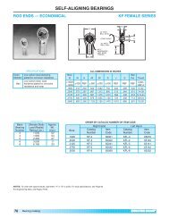
For ordering information<br />
See Page 233.<br />
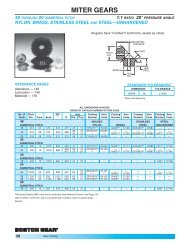
<strong>200</strong> SERIES FLANGED REDUCER DIMENSIONS<br />
90°<br />
-20°<br />
+30°<br />
D<br />
E<br />
A<br />
OUTPUT KEY<br />
–Y–<br />
(FURNISHED)<br />
CC<br />
HOLLOW SHAFT F<strong>200</strong> SERIES<br />
F221–247 SIZES<br />
ALL DIMENSIONS IN INCHES<br />
B S<br />
NEMA Mounting NEMA Mounting<br />
56C 56C<br />
Size A 140TC 180TC 210TC D E F G K N P R 140TC 180TC 210TC<br />
221 6.19 6.13 – – 2.25 3.31 1.06 3.31 .41 2.19 2.12 4.31 1.81 — —<br />
226 7.50 6.69 – – 2.25 3.31 1.06 4.06 .41 2.81 2.60 5.19 1.50 — —<br />
231 8.88 7.19 8.06 – 2.63 3.69 1.06 4.75 .41 3.44 3.11 5.88 1.31 2.19 —<br />
239 11.19 7.94 9.06 9.06 2.63 3.69 1.06 5.44 .41 4.03 3.89 6.69 1.25 2.38 2.38<br />
247 12.88 – 9.56 10.31 3.00 4.31 1.31 5.94 .94 4.88 4.67 7.31 — 2.25 3.00<br />
T Output Optional<br />
NEMA Mounting W<br />
Y<br />
Reaction Rod Kit<br />
56C +.001<br />
Item<br />
Size 140TC 180TC 210TC –.000 X Sq. LGTH. Z AA CC Catalog # Code<br />
221 6.56 — — 1.0000 .50 1/4 x 7/32 1-3/8 1.3750 10-32 18-12 X221-76K 24188<br />
226 6.56 — — 1.2500 .56 1/4 x 7/32 1-1/2 1.7702 1/4-28 30-24 X226-76K 24190<br />
231 6.56 9.25 — 1.4375 .56 3/8 x 5/16 1-3/4 2.1638 1/4-28 30-24 X231-76K 24192<br />
239 6.56 9.25 10.13 1.9375 .63 1/2 x 3/8 2 2.5575 5/16-24 30-24 X239-76K 24194<br />
247 — 9.25 10.13 2.1875 .69 1/2 x 3/8 2-1/4 2.9512 3/8-24 30-24 X247-76K 24196<br />
Refer to Page 248 for Shaft Kit and for Reaction Rod Kit.<br />
Note: For external reference surfaces, refer to page 247.<br />
(2) K-DIA. HOLES<br />
Z-DIA.<br />
(BOTH<br />
ENDS)<br />
X<br />
W-BORE<br />
(3) AA-SOCKET<br />
SETSCREWS<br />
120° APART<br />
F<br />
R<br />
G<br />
B<br />
S<br />
N<br />
P<br />
T<br />
<strong>200</strong> Series<br />
243<br />
J
J<br />
For ordering information<br />
See Page 233.<br />
ASSEMBLY<br />
TYPES*<br />
H1 STANDARD<br />
H2<br />
244 <strong>200</strong> Series<br />
<strong>200</strong> SERIES FLANGED REDUCER DIMENSIONS<br />
H3<br />
H4<br />
K<br />
PARALLEL SHAFTS F<strong>200</strong> SERIES<br />
HORIZONTAL BASE PROJECTING SHAFT<br />
CD E<br />
N<br />
A<br />
M<br />
G<br />
U<br />
(4) T DIA.<br />
HOLES<br />
OUTPUT KEY<br />
W<br />
Input<br />
NEMA<br />
Bore<br />
+.0015<br />
Mounting -.0000 Keyway<br />
56C .625 3/16 × 3/32<br />
140TC .875 3/16 × 3/32<br />
180TC 1.125 1/4 × 1/8<br />
210TC 1.375 5/16 × 5/32<br />
J<br />
NEMA Mounting<br />
Size C.D. A B D E G H 56C 140TC 180TC 210TC K M N<br />
221 2.12 8.75 6.00 4.75 2.72 .50 2.16 8.50 — — — 6.84 3.63 7.25<br />
226 2.60 11.00 7.38 5.75 3.56 .63 2.59 9.56 9.56 — — 8.38 4.50 9.00<br />
231 3.11 12.50 8.50 6.75 4.13 .75 2.72 10.34 10.84 11.22 — 9.88 5.13 10.25<br />
239 3.89 15.50 9.75 7.75 4.94 .88 3.38 — 11.84 12.97 12.97 12.34 6.50 13.00<br />
247 4.67 17.50 10.75 8.50 5.94 1.00 3.81 — 13.97 13.53 14.72 14.19 7.50 15.00<br />
R<br />
Low Speed Shaft Optional<br />
NEMA Mounting<br />
T<br />
U<br />
+.000<br />
W-Key<br />
Approx.<br />
Weight<br />
Base<br />
Kit No.<br />
Output Shaft<br />
Kit<br />
Size P 56C 140TC 180TC 210TC Holes –.001 V Sq. LENGTH (Lbs.) (Ref. Pg 247) (Ref. Pg 246)<br />
221 3.75 6.56 — — — 13/32 1.0000 2.25 1/4 1-1/4 28 X221-11HK X221-3PK<br />
226 4.62 6.56 6.56 — — 15/32 1.2500 2.75 1/4 1-5/8 43 X226-11HK X226-3PK<br />
231 5.44 6.56 6.56 9.25 — 17/32 1.3750 3.00 5/16 1-3/4 69 X231-11HK X231-3PK<br />
239 6.75 — 6.96 9.25 10.13 19/32 1.8750 3.75 1/2 2 124 X239-11HK X239-3PK<br />
247 7.75 — 9.25 10.13 10.13 21/32 2.1250 4.25 1/2 2-1/2 166 X247-11HK X247-3PK<br />
ASSEMBLY<br />
TYPES*<br />
A<br />
R<br />
V<br />
H D<br />
J<br />
B<br />
PARALLEL SHAFTS F<strong>200</strong> SERIES<br />
VERTICAL BASE PROJECTING SHAFT<br />
J<br />
Input<br />
G<br />
P<br />
NEMA<br />
Bore<br />
+.0015<br />
V1<br />
V<br />
Mounting -.0000 Keyway<br />
STANDARD (4) T DIA.<br />
HOLES<br />
OUTPUT KEY<br />
W<br />
U<br />
56C<br />
140TC<br />
.625<br />
.875<br />
3/16 × 3/32<br />
3/16 × 3/32<br />
E<br />
CD F<br />
180TC 1.125 1/4 × 1/8<br />
N<br />
D<br />
210TC 1.375 5/16 × 5/32<br />
V2<br />
M<br />
B<br />
ALL DIMENSIONS IN INCHES<br />
J<br />
NEMA Mounting<br />
Size C.D. A B D E F G 56C 140TC 180TC 210TC M N<br />
221 2.12 6.19 8.00 5.75 2.88 1.97 .50 6.53 — — — 8.25 5.75<br />
226 2.60 7.50 9.63 7.00 3.50 2.56 .63 7.13 7.13 — — 9.88 7.00<br />
231 3.11 8.88 11.00 8.25 4.13 3.13 .75 7.69 8.19 8.88 — 11.25 8.25<br />
239 3.89 11.19 13.63 10.25 5.13 3.56 .88 — 8.75 9.88 9.88 13.88 10.25<br />
247 4.67 12.88 15.50 11.75 5.88 4.31 1.00 — — 10.31 9.88 16.00 11.75<br />
R<br />
Low Speed Shaft Optional<br />
NEMA Mounting<br />
T<br />
U<br />
+.000<br />
W-Key<br />
Approx.<br />
Weight<br />
Base<br />
Kit No.<br />
Output Shaft<br />
Kit<br />
Size P 56C 140TC 180TC 210TC Holes –.001 V Sq. LENGTH (Lbs.) (Ref. Pg 247) (Ref. Pg 246)<br />
221 1.97 6.56 — — — 13/32 1.0000 2.25 1/4 1-1/4 28 X221-11VK X221-3PK<br />
226 2.44 6.56 6.56 — — 15/32 1.2500 2.75 1/4 1-5/8 43 X226-11VK X226-3PK<br />
231 2.66 6.56 6.56 9.25 — 17/32 1.3750 3.00 5/16 1-3/4 69 X231-11VK X231-3PK<br />
239 3.09 — 6.96 9.25 10.13 19/32 1.8750 3.75 1/2 2 124 X239-11VK X239-3PK<br />
247 3.66 — 9.25 10.13 10.13 21/32 2.1250 4.25 1/2 2-1/2 166 X247-11VK X247-3PK<br />
* Assemblies define output (slow speed) shaft projection with respect to input (high speed) shaft and mounting<br />
surface, viewed from end of output shaft. Input may be rotated clockwise or counterclockwise. Input and Output shafts<br />
of Single reduction (S) units rotate in opposite directions, Double reduction (D) units in the same direction.<br />
R<br />
P
For ordering information<br />
See Page 233.<br />
<strong>200</strong> SERIES NON-FLANGED REDUCER DIMENSIONS<br />
90°<br />
-20°<br />
+30°<br />
D<br />
E<br />
HOLLOW SHAFT <strong>200</strong> SERIES<br />
221–247 SIZES<br />
ALL DIMENSIONS IN INCHES<br />
Size A B D E F G K N P R S<br />
221 6.19 5.88 2.25 3.31 1.06 3.31 .41 2.19 2.12 4.31 1.50<br />
226 7.50 7.50 2.25 3.31 1.06 4.06 .41 2.19 2.60 5.18 2.31<br />
231 8.88 8.37 2.62 3.69 1.06 4.75 .41 3.44 3.11 5.88 2.50<br />
239 11.19 10.25 2.62 3.69 1.06 5.44 .41 4.03 3.89 6.69 3.56<br />
247 12.88 10.88 3.00 4.31 1.31 5.94 .41 4.88 4.67 7.31 3.56<br />
High Speed Shaft Low Speed Shaft Optional*<br />
T<br />
+.000<br />
V W<br />
+.001<br />
Y<br />
CC<br />
Reaction Rod Kit<br />
Catalog Item<br />
Size –.001 U Sq. Lgth. –.000 X Size Lgth. Z AA Max-Min Number Code<br />
221 .5000 2.00 1/8 7/8 1.0000 .50 1/4 x 7/32 1-3/8 1.3750 #10-32 18-12 X221-76K 24188<br />
226 .6250 2.88 3/16 1 1.2500 .56 1/4 x 7/32 1-1/2 1.7702 1/4-28 30-24 X226-76K 24190<br />
231 .9375 3.06 1/4 1-1/4 1.4375 .56 3/8 x 5/16 1-3/4 2.1638 1/4-28 30-24 X231-76K 24192<br />
239 1.3750 4.19 5/16 2-7/16 1.9375 .62 1/2 x 3/8 2 2.5575 5/16-24 30-24 X239-76K 24194<br />
247 1.5675 4.25 3/8 2-1/4 2.1875 .69 1/2 x 3/8 2-1/4 2.9512 3/8-24 30-24 X247-76K 24196<br />
* See page 248 for <strong>dimensions</strong><br />
A<br />
OUTPUT KEY<br />
–Y–<br />
(FURNISHED)<br />
CC<br />
(2) K-DIA. HOLES<br />
(3) AA-SOCKET<br />
SETSCREWS<br />
120° APART<br />
N<br />
P<br />
X<br />
F<br />
R<br />
G<br />
B<br />
U<br />
S<br />
W-BORE Z-DIA.<br />
(BOTH ENDS)<br />
T<br />
INPUT KEY<br />
–V–<br />
<strong>200</strong> Series<br />
245<br />
J
J<br />
For ordering information<br />
See Page 233.<br />
ASSEMBLY TYPES*<br />
H1 STANDARD<br />
H2<br />
Low Speed Shaft High Speed Shaft Optional<br />
T<br />
U<br />
+.000<br />
W-Key X<br />
+.000<br />
Z-Key Approx.<br />
Weight<br />
Base<br />
Kit No.<br />
Output Shaft<br />
Kit No.<br />
Size C.D. Holes –.001 V Sq. Lgth. –.001 Y Sq. Lgth. (Lbs.) (Ref. page 249) (Ref. page 248)<br />
221 2.12 13/32 1.0000 2.25 1/4 1-1/4 .5000 2.06 1/8 7/8 22 X221-11HK X221-3PK<br />
226 2.60 15/32 1.2500 2.75 1/4 1-1/4 .6250 2.88 3/16 1 39 X226-11HK X226-3PK<br />
231 3.11 17/32 1.3750 3.00 5/16 1-3/4 .9375 3.06 1/4 1-1/4 60 X231-11HK X231-3PK<br />
239 3.89 19/32 1.8750 3.75 1/2 2 1.3750 4.19 5/16 2-7/16 104 X239-11HK X239-3PK<br />
247 4.67 21/32 2.1250 4.25 1/2 2-1/2 1.5625 4.25 3/8 2-1/4 148 X247-11HK X247-3PK<br />
246 <strong>200</strong> Series<br />
<strong>200</strong> SERIES NON-FLANGED REDUCER DIMENSIONS<br />
H3<br />
H4<br />
E<br />
CD<br />
J<br />
N<br />
A<br />
K<br />
(4) T DIA.<br />
HOLES<br />
OUTPUT KEY<br />
W<br />
Size C.D. A B C D E G H J K M N P<br />
221 2.12 8.75 6.00 6.72 4.75 2.72 .50 2.16 3.63 6.84 8.25 7.25 3.75<br />
226 2.60 11.00 7.38 8.59 5.75 3.56 .63 2.59 4.50 8.38 10.38 9.00 4.62<br />
231 3.11 12.50 8.50 9.69 6.75 4.13 .75 2.72 5.13 9.88 11.53 10.25 5.44<br />
239 3.89 15.50 9.75 11.78 7.75 4.94 .88 3.38 6.50 12.34 14.16 13.00 6.75<br />
247 4.67 17.50 10.75 12.59 8.50 5.94 1.00 3.81 7.50 14.19 15.28 15.00 7.75<br />
ASSEMBLY TYPES*<br />
V1 STANDARD<br />
V2<br />
PARALLEL SHAFTS <strong>200</strong> SERIES<br />
HORIZONTAL BASE<br />
P<br />
(4) T DIA.<br />
HOLES<br />
E<br />
A<br />
N<br />
M<br />
K<br />
OUTPUT KEY<br />
W<br />
Size C.D. A B D E F G H K M N P<br />
221 2.12 6.19 8.00 5.75 2.88 1.97 .50 6.28 8.25 8.25 5.75 1.97<br />
226 2.60 7.50 9.63 7.00 3.50 2.56 .63 7.94 10.38 9.88 7.00 2.44<br />
231 3.11 8.88 11.00 8.25 4.13 3.13 .75 8.88 11.53 11.25 8.25 2.66<br />
239 3.89 11.19 13.63 10.25 5.13 3.56 .88 11.06 14.16 13.88 10.25 3.09<br />
247 4.67 12.88 15.50 11.75 5.88 4.31 1.00 11.63 15.28 16.00 11.75 3.66<br />
H<br />
G<br />
P<br />
Y<br />
INPUT KEY<br />
Z<br />
ALL DIMENSIONS IN INCHES<br />
INPUT KEY<br />
Z<br />
X<br />
E<br />
Y<br />
X<br />
D<br />
B<br />
C<br />
M<br />
U<br />
V<br />
CD F<br />
D<br />
B<br />
ALL DIMENSIONS IN INCHES<br />
V<br />
G<br />
H<br />
U<br />
PROJECTING SHAFT<br />
PARALLEL SHAFTS <strong>200</strong> SERIES<br />
VERTICAL BASE<br />
PROJECTING SHAFT<br />
Low Speed Shaft High Speed Shaft Optional<br />
T<br />
U<br />
+.000<br />
W-Key X<br />
+.000<br />
Z-Key Approx.<br />
Weight<br />
Base<br />
Kit No.<br />
Output Shaft<br />
Kit No.<br />
Size C.D. Holes –.001 V Sq. Lgth. –.001 Y Sq. Lgth. (Lbs.) (Ref. page 249) (Ref. page 248)<br />
221 2.12 13/32 1.0000 2.25 1/4 1-1/4 .5000 2.06 1/8 7/8 22 X221-11VK X221-3PK<br />
226 2.60 15/32 1.2500 2.75 1/4 1-1/4 .6250 2.88 3/16 1 39 X226-11VK X226-3PK<br />
231 3.11 17/32 1.3750 3.00 5/16 1-3/4 .9375 3.06 1/4 1-1/4 60 X231-11VK X231-3PK<br />
239 3.89 19/32 1.8750 3.75 1/2 2 1.3750 4.19 5/16 2-7/16 104 X239-11VK X239-3PK<br />
247 4.67 21/32 2.1250 4.25 1/2 2-1/2 1.5625 4.25 3/8 2-1/4 148 X247-11VK X247-3PK<br />
* Assemblies define output (slow speed) shaft projection with respect to input (high speed) shaft and mounting surface, viewed from end of output shaft. Input may<br />
be rotated clockwise or counterclockwise.<br />
• Input and Output shafts of Single reduction (S) units rotate in opposite directions, Double reduction (D) units in the same direction.
C<br />
<strong>200</strong> SERIES OPTIMOUNT ® DIMENSIONS<br />
L<br />
D<br />
N<br />
EXTERNAL REFERENCE SURFACES <strong>200</strong> SERIES<br />
221–247 SIZES<br />
M<br />
J<br />
K<br />
E F<br />
G<br />
N<br />
(8) “H” TAPPED<br />
HOLES 90°<br />
APART<br />
A<br />
B<br />
+.002<br />
C*<br />
+.000<br />
D*<br />
+.000<br />
E*<br />
+.000<br />
H<br />
Size ±.005 -.000 -.010 -.003 -.004 F G Size Depth J K L M N<br />
221 .904 2.123 6.193 5.998 2.000 .19 2.38 1/4-20 9/16 4.31 3.31 .50 .66 .44<br />
226 .936 2.595 7.495 7.248 2.062 .38 2.81 5/16-18 5/8 5.19 4.06 .56 1.00 .69<br />
231 1.000 3.114 8.870 8.624 2.625 .34 3.31 3/8-16 3/4 5.88 4.75 .56 1.06 .69<br />
239 1.560 3.893 11.182 10.936 3.312 .34 4.00 3/8-16 3/4 6.69 5.44 .62 1.06 .69<br />
247 1.560 4.671 12.870 12.624 3.687 .38 4.44 7/16-14 7/8 7.31 5.94 .69 1.12 .75<br />
*Tolerance on Dimensions Apply Only to Housing before Painting.<br />
ALL DIMENSIONS IN INCHES<br />
45°<br />
A<br />
B<br />
<strong>200</strong> Series<br />
247<br />
J
J<br />
CC<br />
Kit<br />
Catalog Item<br />
Size AA BB Sq. Lgth. D E F G H J K Number Code<br />
221<br />
226<br />
231<br />
239<br />
247<br />
.9995<br />
.9985<br />
2-1/4 1/4 1-1/4 .12 1/4 x 1/8 x 1-13/32 4.47 6.84<br />
.9998<br />
.9988<br />
1.16 1.45 X221-3PK 23888<br />
1.2495<br />
1.2485<br />
2-3/4 1/4 1-1/4 .12 1/4 x 1/8 x 1-17/32 5.38 8.25<br />
1.2498<br />
1.2488<br />
1.41 1.83 X226-3PK 23892<br />
1.3745<br />
1.3735<br />
3 5/16 1-3/4 .16 3/8 x 3/16 x 1-25/32 6.09 9.25<br />
1.4373<br />
1.4363<br />
1.62 2.75 X231A-3PK 63124<br />
1.8745<br />
1.8735<br />
3-3/4 1/2 2 .16 1/2 x 1/4 x 2-1/32 7.00 10.91<br />
1.9373<br />
1.9363<br />
2.12 2.33 X239-3PK 23904<br />
2.1245<br />
2.1235<br />
4-1/4 1/2 2-1/2 .16 1/2 x 1/4 x 2-9/32 7.26 12.03<br />
2.1873<br />
2.1863<br />
2.44 2.51 X247-3PK 23910<br />
248 <strong>200</strong> Series<br />
<strong>200</strong> SERIES SHAFT KITS / REACTION ROD KITS<br />
STEEL PROJECTING OUTPUT SHAFTS (INSERTABLE)<br />
REACTION ROD KITS<br />
BB*<br />
Kit<br />
Catalog Item<br />
Size AA Max. Min. CC DD EE FF GG HH JJ KK LL MM Number Code<br />
221 2.25 18 12 .41 .38 4.50 1.06 .16 .78 3.31 1/4-20 x 1-3/4 lg. .62 .64 X221-76K 24188<br />
226 2.25 30 24 .41 .50 10 1.06 .16 .78 3.31 1/4-20 x 2-1/4 lg. .66 .94 X226-76K 24190<br />
231 2.62 30 24 .41 .62 10 1.06 .19 .94 3.69 5/16-18 x 2-1/2 lg. .81 1.12 X231-76K 24192<br />
239 2.62 30 24 .41 .62 10 1.06 .19 .94 3.69 3/8-16 x 2-3/4 lg. .91 1.44 X239-76K 24194<br />
247 3.00 30 24 .47 .75 10 1.31 .21 1.12 4.21 7/16-14 x 3 lg. 1.03 1.41 X247-76K 24196<br />
* BB dimension can be reduced by cutting off threaded rods.<br />
INSTALLATION INFORMATION<br />
The ideal position of the reaction rod is at 90° from a line<br />
drawn through the center of the hollow shaft and the point<br />
where reaction rod is attached to the housing or bracket.<br />
This is illustrated in Figure 1, along with allowable angular<br />
deviations.<br />
221 to 247 252 & 259<br />
AA<br />
(CC) KEY<br />
ALL DIMENSIONS IN INCHES ORDER BY CATALOG NUMBER OR ITEM CODE<br />
ALL DIMENSIONS IN INCHES ORDER BY CATALOG NUMBER OR ITEM CODE<br />
90° 90°<br />
±30°<br />
90° -20°<br />
90° +30°<br />
-20°<br />
+30° ±30°<br />
90° ±15°<br />
FF<br />
HH<br />
BB<br />
AA<br />
JJ<br />
Figure 2 illustrates in a typical<br />
manner the possible reaction rod<br />
positions for shaft mounted<br />
reducers in horizontal or vertical<br />
positions.<br />
NOTE: The reaction rod must be<br />
attached to the housing<br />
only at the screw<br />
locations identified by<br />
the spot faced surfaces<br />
or to the reaction rod<br />
bracket attached to the<br />
housing.<br />
90° ±15°<br />
BB<br />
DD<br />
EE<br />
GG<br />
(E)<br />
KEYWAY<br />
K<br />
D<br />
CC HOLES<br />
J H<br />
G<br />
RETAINING<br />
RING GROOVE<br />
F (REF.)<br />
LOCKWASHER<br />
PLAIN<br />
WASHER<br />
SPEC. BUSHING<br />
MM<br />
LL<br />
(1)-(KK) SOCKET<br />
HEAD CAP SCREW<br />
DO NOT USE<br />
LOCKWASHER IN C'BORE<br />
HOUSING<br />
Figure 2
BASE KITS (CAST IRON)<br />
<strong>200</strong> SERIES BASE KITS<br />
HORIZONTAL<br />
Kit Item<br />
Catalog No. Code<br />
X221-11HK 68643<br />
X226-11HK 68654<br />
X231-11HK 68656<br />
X239-11HK 68658<br />
X247-11HK 68660<br />
VERTICAL<br />
Kit Item<br />
Catalog No. Code<br />
X221-11VK 68644<br />
X226-11VK 68655<br />
X231-11VK 68657<br />
X239-11VK 68659<br />
X247-11VK 68661<br />
<strong>200</strong> Series<br />
249<br />
J
J<br />
<strong>200</strong> SERIES – BOST-KLEEN <br />
• WASHABLE AND SCRUBBABLE<br />
250 <strong>200</strong> Series<br />
<strong>200</strong> SERIES OPTIMOUNT ® WASHDOWN DUTY<br />
• DURABLE, NON-ABSORBENT, NON-TOXIC<br />
WHITE EPOXY FINISH, USDA APPROVED<br />
• CORROSION RESISTANT<br />
• 1/4 TO 20 HORSEPOWER RANGE<br />
• SINGLE AND DOUBLE REDUCTION RATIOS – 4:1 TO 24:1<br />
• STANDARD NEMA C-FACE AND PROJECTING<br />
INPUT SHAFT CONFIGURATIONS<br />
• PARALLEL SHAFTS<br />
• HORIZONTAL AND VERTICAL MOUNTING KITS<br />
• PROJECTING AND HOLLOW OUTPUT SHAFTS<br />
STAINLESS BOST-KLEEN <br />
Bost-Kleen <br />
WAS H D O W N<br />
Stainless Bost-Kleen <br />
WAS H D O W N<br />
• INCLUDES ALL THE FEATURES OF THE STANDARD WHITE<br />
BOST-KLEEN REDUCERS<br />
• U.S.D.A. APPROVED FOR USE IN FOOD PROCESSING AND<br />
HANDLING INDUSTRY WHERE INCIDENTAL FOOD<br />
CONTACT MAY OCCUR<br />
• DURABLE STAINLESS STEEL EPOXY COATING SYSTEM<br />
UTILIZES A UNIQUE #316L STAINLESS STEEL LEAFING<br />
PIGMENT. THIS CATALYZED SYSTEM CREATES A HARD,<br />
NON-TOXIC METALLIC FINISH<br />
BISSC CERTIFIED BASIC MODEL NUMBERS, DIMENSIONS AND AVAILABLE RATIOS<br />
WHITE BOST-KLEEN STAINLESS BOST-KLEEN INPUT OUTPUT<br />
SHAFT SHAFT<br />
NON- QUILL NON-FLANGED QUILL CENTER NEMA DIA. DIA. AVAILABLE<br />
FLANGED TYPE TYPE TYPE DISTANCE MOUNTING +.000 +.000 RATIOS<br />
TYPE -.001 -.001<br />
BK221 BKF221 SBK221 SBKF221 2.12 56C .500 1.000 4,10,14,17,20,24<br />
BK226 BKF226 SBK226 SBKF226 2.60 56C,140TC .625 1.2500 4,10,14,17,20,24<br />
BK231 BKF231 SBK231 SBKF231 3.11 56C,140TC,180TC .9375 1.3750 4,10,14,17,20,24<br />
BK239 BKF239 SBK239 SBKF239 3.89 140TC,180TC,210TC 1.375 1.8750 4,10,14,17,20,24<br />
BK247 BKF247 SBK247 SBKF247 4.67 180TC,210TC 1.5625 2.1250 4,10,14,17,20,24
<strong>200</strong> SERIES OPTIMOUNT ® HELICAL GEAR SPEED REDUCERS<br />
General Instructions<br />
1. When mounting, use maximum possible bolt<br />
size and secure gear drive to a rigid foundation.<br />
Periodic inspection of all bolts is recommended.<br />
2. Align all shafts accurately. Improper alignment<br />
can result in failure. Use of flexible couplings<br />
is recommended to compensate for slight<br />
misalignment.<br />
3. Arrange the drain and breather plug per your<br />
mounting position as indicated on page 252.<br />
The breather plug should also be located in the<br />
Fill position.<br />
4. Auxiliary drive components (such as sprockets,<br />
gears and pulleys) should be mounted on the<br />
shafts as close as possible to the housing to<br />
minimize effects of overhung loads. Avoid force<br />
fits that might damage bearings or gears.<br />
5. <strong>Gear</strong> drives are nameplated for 1750 RPM<br />
Input Speed and Class I Service. For lower<br />
Input Speeds and other Service Class, refer to<br />
catalog rating information.<br />
INSTALLATION, LUBRICATION<br />
and OPERATION INSTRUCTIONS<br />
Warning: <strong>Boston</strong> <strong>Gear</strong> speed reducers are normally shipped without lubricant. They must be<br />
filled to the proper level with the recommended lubricant before operation.<br />
CAUTION<br />
• For safe operation of any gear drive, all rotating shafts<br />
and auxiliary components must be shielded<br />
to conform with applicable safety standards. You must<br />
consider overall operational system safety at all times.<br />
• When using a gear drive to raise or lower a load, such<br />
as in hoisting applications, provision must be made for<br />
external braking. Under no conditions should a speed<br />
reducer be considered self-locking.<br />
• Mounting of speed reducers in overhead positions may<br />
be hazardous. Use of external guides or supports is<br />
strongly recommended for overhead mounting.<br />
6. Input Speeds of 1750 and lower are shown in<br />
catalog rating tables for speed reducing<br />
applications. This does not represent the<br />
maximum speed. Since speed limitation is<br />
based on pitching velocity and varies with size<br />
and ratio.<br />
Shaft Mounted Installation<br />
Mount reducer on the shaft to be driven, as close<br />
to the supporting bearing as possible, and tighten<br />
end setscrews. For installations requiring an<br />
adapter bushing, the setscrews must pass through<br />
clearance holes in the bushing. For severe applications,<br />
the driven shaft should be spot drilled for<br />
these setscrews.<br />
Instructions for Flanged Models<br />
F<strong>200</strong> (Quill Type Input)<br />
1. Assemble the key to the motor shaft and coat<br />
the shaft with anti-seize compound. Insert the<br />
motor shaft into the reducer input shaft.<br />
2. Rotate the motor to proper position and firmly<br />
secure to flange with four hex-head cap screws.<br />
CAUTION - If the motor does not readily seat<br />
itself, check to determine if key has moved axially<br />
along motor shaft, causing interference. Staking of<br />
the keyway adjacent to the motor key will facilitate<br />
this procedure.<br />
Location of Filler, Level and<br />
Drain Plugs<br />
Optimount reducers may be mounted in any<br />
position shown with the following exceptions:<br />
Filler, level and drain plugs are completely interchangeable<br />
and should be arranged to suit the<br />
required mounting positions. Four (4) pipe tapped<br />
holes for these plugs are located on the input shaft<br />
side of the housing and one (1) on the opposite<br />
side.<br />
<strong>200</strong> Series<br />
251<br />
J
J<br />
<strong>200</strong> SERIES OPTIMOUNT ® ASSEMBLY TYPES & LUBRICATION<br />
<strong>200</strong> SERIES HORIZONTAL BASE<br />
H1<br />
<strong>200</strong> SERIES VERTICAL BASE<br />
Recommended Lubricants<br />
The following tables indicate the type and viscosity<br />
of lubricant suitable for reducers operating at various<br />
temperatures.<br />
Lubrication and maintenance instructions are provided<br />
with each speed reducer. These instructions<br />
should be followed for best results. It is important<br />
that the proper type of oil be used since many oils<br />
are not suitable for the lubrication of gears. Various<br />
types of gearing require different types of lubricants.<br />
The lubricant must remain free from oxidation and<br />
contamination by water or debris since only a very<br />
thin film of oil stands between efficient operation and<br />
failure. To assure long service life, the reducer<br />
should be periodically drained (preferably while<br />
warm) and refilled to the proper level with a<br />
recommended gear oil. Under normal environmental<br />
conditions oil changes, are suggested after the initial<br />
250 hours of operation, and thereafter, at regular<br />
intervals of 2500 hours or every 6 months. Synthetic<br />
lubricants will allow extended lubrication intervals<br />
due to its increased resistance to thermal and<br />
oxidation degradation. It is suggested that the initial<br />
oil change be made at 1500 hours and, thereafter, at<br />
5000 hour intervals.<br />
During the initial period of operation, higher than<br />
normal operating temperatures may be seen. This is<br />
due to the initial break-in of the gear set. The<br />
temperature of Helical <strong>Gear</strong> Reducers may reach<br />
160°F.<br />
252 <strong>200</strong> Series<br />
ASSEMBLY TYPES<br />
IN L<br />
IN<br />
IN L IN<br />
V1<br />
H2<br />
H3 D<br />
H4<br />
D<br />
F<br />
D<br />
F<br />
ASSEMBLY TYPES<br />
F<br />
V2<br />
D<br />
F<br />
L<br />
F<br />
D<br />
F<br />
D<br />
L<br />
Enclosed Helical<br />
Recommended Viscosity<br />
Ambient (Room) Oil (or Range S&S Lubricant ISO Viscosity<br />
Temperature equivalent) @ 100°F AGMA No. Grade No.<br />
–30° to 225°F ‡ Klubersynth*<br />
(-34°C to 107°C) UH1 6-460<br />
–30° to 225°F ‡ Mobile<br />
(-34°C to 107°C) SHC634<br />
1950/2500 — 460<br />
1950/2500 — 320 / 460<br />
<strong>Boston</strong> <strong>Gear</strong><br />
Recommended Item Code<br />
Lubricant Quart<br />
Klubersynth UH1 6-460 65159<br />
Mobile SHC634 51493<br />
CAUTION: Relubricate more frequently, if drive is operated in high ambient<br />
temperatures or unusually contaminated atmospheres. High loads<br />
and operating temperatures will also require more frequent<br />
relubrication.<br />
* Synthetic recommendation is exclusively for Klubersynth UH1 6-460.<br />
‡ The UH1 6-460 lubricant will perform at temperatures considerably higher<br />
than 225°F. However, the factory should always be consulted prior to<br />
operating at higher temperatures, as damage may occur to oil seals and<br />
other components.<br />
Drain Plug must be installed in the lower most<br />
location of the housing. This plug will be on the<br />
input shaft side of the housing for positions H1,<br />
H3, H4 and V2. The opposite for position V1 and<br />
may be either side for H2.<br />
The Vented Filler Plug should be installed in the<br />
uppermost location. This plug will be on the input<br />
shaft side for positions H1, H2, or H3, on either<br />
side for H4 and must be tightened into position<br />
with the arrow pointing upward.<br />
For vertical mounting (V1 and V2), this plug must<br />
be tightened with arrow pointing toward the center.<br />
Level Plug position will be as indicated for<br />
horizontal positions. For vertical positions the oil<br />
level is established by an oil level distance<br />
measured from the outer surface of the housing<br />
from the oil filler hole.<br />
Single Reduction Double Reduction<br />
Size Oil Dist. Capacity Oil Dist. Capacity<br />
(Inches) (Qts) (Inches) (Qts)<br />
221 1.25 .38 1.00 .50<br />
226 1.62 .75 1.38 1.00<br />
231 2.00 1.25 1.62 1.50<br />
239 2.12 2.75 1.88 3.00<br />
247 2.25 4.00 1.88 4.25
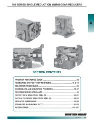
<strong>200</strong> SERIES PARTS LIST — SINGLE AND DOUBLE REDUCTION<br />
MODELS 221-247<br />
18<br />
19<br />
20<br />
23<br />
22<br />
34<br />
36<br />
24<br />
1<br />
12 63 17<br />
61<br />
35<br />
14<br />
5<br />
11<br />
6 44<br />
16 13<br />
3<br />
14 15<br />
43<br />
7<br />
31<br />
1A<br />
28<br />
30<br />
4<br />
8<br />
ITEM ITEM ITEM<br />
NO. DESCRIPTION OF PART NO. DESCRIPTION OF PART NO. DESCRIPTION OF PART<br />
1 Housing, Body 22 Pipe Plug 44 Hex. Soc. Setscrew<br />
1A Housing, Cover 23 Plastic Plug 45 Rolled Washer (For 226-247)<br />
2 Helical <strong>Gear</strong> (Output) 24 Vented Oil Filler 46 Bore Plug<br />
3 Hollow Output Shaft 25 Dowel Pin 47 N/A<br />
4 Solid Output Shaft, Insert 26 Soc. Head Capscrew 48 Clevis<br />
4A N/A 27 Lockwasher 49 Bushing<br />
5 Ball Bearing 28 Ball Bearing 50 Soc. Head Capscrew<br />
6 Key, Output <strong>Gear</strong> 29 Interm. Helical Pinion 51 Hex Head Capscrew<br />
7 Key 30 Interm. Helical <strong>Gear</strong> 52 Lockwasher<br />
8 Key 31 Key, Interm. <strong>Gear</strong> 53 Flatwasher<br />
9 N/A 32 Vertical Base 54 Nut<br />
10 Shim 33 Soc. Head Capscrew 55 Nut, Left Hand<br />
11 Input Helical Pinion 34 Horizontal Base 56 Nut, Lock<br />
12 Ball Bearing 35 Soc. Head Capscrew` 57 Turnbuckle<br />
13 Ball Bearing 36 Nameplate 58 Eyebolt, Rod End (Left Hand)<br />
14 Retaining Ring (For 221 Only) 37 Button Hd. Capscrew (For 226-247) 59 Eyebolt, Rod End<br />
15 Retaining Ring 38 Soc. Head Capscrew 61 Lockwasher<br />
16 Bearing Retainer (For 226-247) 39 Lockwasher 62 Hex. Soc. Setscrew<br />
17 Key 40 Motor Flange 63 Retaining Ring<br />
18 Oil Seal 41 Hex Head Capscrew<br />
19 Bore Plug 42 Motor Shaft (Input)<br />
20 Oil Seal 43 Retaining Ring<br />
21 Oil Seal<br />
PART ORDERING INFORMATION: Be sure to provide complete <strong>Boston</strong> <strong>Gear</strong> catalog number<br />
from speed reducer nameplate, along with part description and number.<br />
29<br />
28<br />
2<br />
1A<br />
5<br />
10<br />
45<br />
37<br />
22<br />
27<br />
26<br />
25<br />
46<br />
19<br />
18<br />
32<br />
61 33<br />
MODELS F221-F247<br />
38<br />
39<br />
21<br />
40<br />
41<br />
62<br />
REACTION ARM KIT<br />
48<br />
51<br />
56<br />
58 55<br />
42<br />
16<br />
57<br />
14<br />
13 14<br />
15<br />
54<br />
<strong>200</strong> Series<br />
53<br />
59<br />
1A<br />
45 37<br />
50<br />
49<br />
52<br />
253<br />
J