A Hybrid Meshing Scheme Based on Terrain Feature Identification
A Hybrid Meshing Scheme Based on Terrain Feature Identification
A Hybrid Meshing Scheme Based on Terrain Feature Identification

Create successful ePaper yourself
Turn your PDF publications into a flip-book with our unique Google optimized e-Paper software.
A<str<strong>on</strong>g>Hybrid</str<strong>on</strong>g> <str<strong>on</strong>g>Meshing</str<strong>on</strong>g> <str<strong>on</strong>g>Scheme</str<strong>on</strong>g> <str<strong>on</strong>g>Based</str<strong>on</strong>g> <strong>on</strong> <strong>Terrain</strong><br />
<strong>Feature</strong> Identificati<strong>on</strong><br />
Volker Berkhahn 1 ,Kai Kaapke 2 ,Sebastian Rath 3 and Erik Pasche 3<br />
1 University ofHannover, Institute of Computer Science in Civil Engineering,<br />
Callinstraße 34, 30167 Hannover, Germany, berkhahn@bauinf.uni-hannover.de<br />
2 University ofNew South Wales, Water Research Laboratory, King Street,<br />
Sydney, 2093, Australia, k.kaapke@wrl.unsw.edu.au<br />
3 University ofTechnology Hamburg, Department ofRiver and Coastal<br />
Engineering, Denickestraße 22, 21073 Hamburg, Germany, S.Rath@tuhh.de,<br />
Pasche@tuhh.de<br />
1Abstract<br />
Hydrodynamic engineering makes profitably use of numerical simulati<strong>on</strong>s which rely<br />
<strong>on</strong> discrete element meshes of the topography. To cope with specific circumstances<br />
in river hydraulics, the presented hybrid meshing scheme comprises following proposals:<br />
river beds and areas of significant terrain slopes are meshed with regular<br />
elements to support user specified edge ratio and element orientati<strong>on</strong> representing<br />
flow gradients appropriately; floodplains are represented as irregular triangle<br />
meshes, c<strong>on</strong>catenating disc<strong>on</strong>nected regular meshes while warranting high approximati<strong>on</strong><br />
quality. Automatic breakline detecti<strong>on</strong> approximates flow relevant changes<br />
in topographic gradients and defines borders of different mesh types. This paper<br />
presents an enhanced strategy for aterrain feature analysis based <strong>on</strong> b-spline analysis<br />
grids and <strong>on</strong> an interpolati<strong>on</strong> scheme for breakline points in order toreduce the<br />
zigzag property ofdetected breaklines. This scheme for terrain analysis and meshing<br />
functi<strong>on</strong>ality isimplemented in the open source software tool <str<strong>on</strong>g>Hybrid</str<strong>on</strong>g>Mesh.<br />
Keywords: <strong>Terrain</strong> feature analysis, breakline identificati<strong>on</strong>, hybrid element meshing<br />
scheme, regular meshes <strong>on</strong> b-spline surfaces, irregular triangle meshes, hydrodynamic<br />
simulati<strong>on</strong>s based <strong>on</strong> finite elements.<br />
2Introducti<strong>on</strong><br />
Hydrodynamic engineering using remote sensing data sources faces growing data<br />
volumes for analysis, forecasts and assessments. Numerical simulati<strong>on</strong>s of water levels,<br />
flow velocities or sediment transport in river and coastal engineering require<br />
element meshes approximating the c<strong>on</strong>sidered topography sufficiently accurate and<br />
while representing all significant terrain features. With respect to implementati<strong>on</strong>
130 Volker Berkhahn et al.<br />
and applicati<strong>on</strong> of these methods, element meshes are supposed to fulfill requirements<br />
regarding edge ratio, element angles and element size. In practice, these requirements<br />
also vary for different characteristic areas of aflooded domain.<br />
The purpose of the suggested hybrid mesh generati<strong>on</strong> algorithm is to generate<br />
meshes for hydrodynamic studies, providing enhanced suitability f or numerical<br />
simulati<strong>on</strong>s schemes. The numerical scheme under c<strong>on</strong>siderati<strong>on</strong> describes flow characteristics<br />
based <strong>on</strong> the depth and time averaged Nav ier-Stokes equati<strong>on</strong>s, widely<br />
known as shallow water wave equati<strong>on</strong>s. The hydrodynamic model for the presented<br />
study is an ancestor of the hydrodynamic model RMA2, which is enhanced for<br />
roughness and turbulence modeling. RMA2 uses the fully implicit implementati<strong>on</strong><br />
of the Galerkin weighted residual technique, originally develope dfor the Resource<br />
Management Associates in Lafayette. Today, RMA2 is internati<strong>on</strong>ally accepted as<br />
hydraulic model for two-dimensi<strong>on</strong>al steady and unsteady flow and well-suited for<br />
mapping inundati<strong>on</strong> areas [FEMA-2004a]. It generally supports the use of triangular<br />
and quadrilateral meshes as well as mixed discretisati<strong>on</strong>s ofthe terrain.<br />
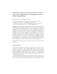
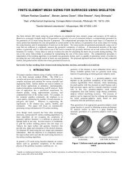
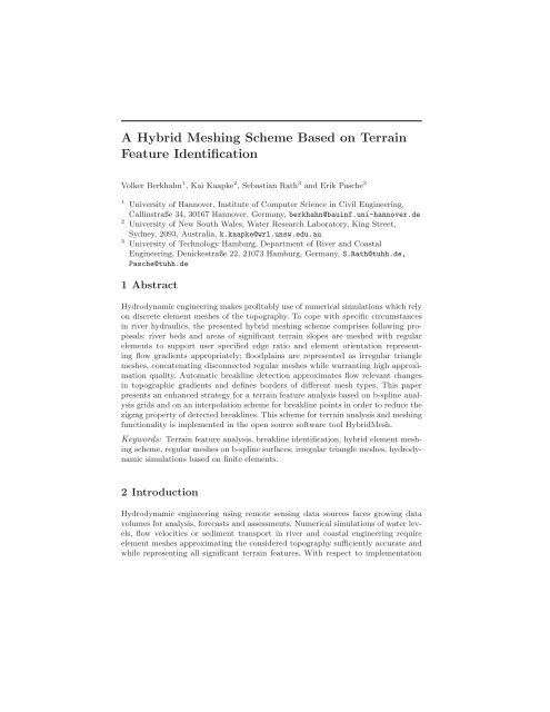
Fig. 1. Topography ofthe River Stoer and the tributary Bramau (case study 1)<br />
visualized with the analysis and meshing tool <str<strong>on</strong>g>Hybrid</str<strong>on</strong>g>Mesh<br />
In this c<strong>on</strong>tributi<strong>on</strong> the hybrid meshing scheme is exemplarily dem<strong>on</strong>strated for<br />
two different case studies. Case study 1represents an alluvial, partly straightened<br />
stream: The River Stoer, located in the lowlands in Northern Germany, is atributary<br />
of the River Elbe. The data basis for simulati<strong>on</strong>s of this stream are airborne LiDAR<br />
topographic survey data in c<strong>on</strong>juncti<strong>on</strong> with bathymetry measurements. Provided as<br />
irregular point cloud with variable density, the average resoluti<strong>on</strong> of the LiDAR data<br />
set offers several measures persquare metre. The bathymetry is gathered from profile<br />
measurements, compacted via linear interpolati<strong>on</strong> schemes to obtain approximately<br />
a5mresoluti<strong>on</strong>. Fig. 1shows aplan view <strong>on</strong>the data set, revealing some lacks in<br />
the terrain coverage due to inundati<strong>on</strong> and impact of tiling.<br />
Case study 2 represents a digital terrain model of a tributary to the River<br />
Danube. Different characteristics of this topography are obvious: The resoluti<strong>on</strong>
A<str<strong>on</strong>g>Hybrid</str<strong>on</strong>g> <str<strong>on</strong>g>Meshing</str<strong>on</strong>g> <str<strong>on</strong>g>Scheme</str<strong>on</strong>g> <str<strong>on</strong>g>Based</str<strong>on</strong>g> <strong>on</strong> <strong>Terrain</strong> <strong>Feature</strong> Identificati<strong>on</strong> 131<br />
of measurement points in the area of the river bed and the river slope is4m. In<br />
c<strong>on</strong>trast tothis, the resoluti<strong>on</strong> in the floodplain area i s20m.Inadditi<strong>on</strong> to these<br />
two different resoluti<strong>on</strong> areas, afine resoluti<strong>on</strong> of 1m is used to describe significant<br />
terrain features in the area ofthe river bed and the floodplain. These different resoluti<strong>on</strong><br />
areas of the topography point out the n ecessity for separate c<strong>on</strong>siderati<strong>on</strong>s of<br />
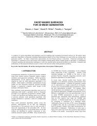
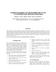
different meshing areas and for ahybrid meshing scheme. Fig. 2shows the original<br />
data set of case study 2aswell as the identified breaklines marked in red.<br />
Fig. 2. Data set of atributary to the River Danube with identified breaklines (case<br />
study 2)<br />
The software tool <str<strong>on</strong>g>Hybrid</str<strong>on</strong>g>Mesh combines the functi<strong>on</strong>ality ofbreakline identificati<strong>on</strong><br />
[RathPasche-2004] and entirely automated meshing. The irregular triangle<br />
meshes are based <strong>on</strong> aDelaunay refinement [RathBajat-2004] and the regular mesh<br />
generati<strong>on</strong> is based <strong>on</strong> free form surfaces [BerkhahnEtAl-2002], [BerkhahnMai-2004a]<br />
[BerkhahnMai-2004b]. This <str<strong>on</strong>g>Hybrid</str<strong>on</strong>g>Mesh tool is developed by the authors ofthis paper<br />
and is an enhancement ofthe HydroMesh tool [Goebel-2005]. <str<strong>on</strong>g>Hybrid</str<strong>on</strong>g>Mesh is<br />
implemented with the Java programming language and will be available as open<br />
source software.<br />
3<str<strong>on</strong>g>Hybrid</str<strong>on</strong>g> <str<strong>on</strong>g>Meshing</str<strong>on</strong>g> <str<strong>on</strong>g>Scheme</str<strong>on</strong>g><br />
The hybrid mesh generati<strong>on</strong> scheme presented by Rath et al. [RathEtAl-2005] c<strong>on</strong>siders<br />
the topography ofriver beds and their adjacent floodplains individually. A<br />
separate c<strong>on</strong>siderati<strong>on</strong> of river beds and their floodplains for mesh generati<strong>on</strong> denotes<br />
the distinct measurement technologies for these sub domains, their accuracy<br />
demands and dominati<strong>on</strong> for numeric simulati<strong>on</strong>s. The individual c<strong>on</strong>siderati<strong>on</strong> of<br />
different topographic sub domains is realized based <strong>on</strong> terrain feature recogniti<strong>on</strong><br />
for breakline identificati<strong>on</strong>.
132 Volker Berkhahn et al.<br />
3.1 Status Quo ofthe <str<strong>on</strong>g>Hybrid</str<strong>on</strong>g> <str<strong>on</strong>g>Meshing</str<strong>on</strong>g> <str<strong>on</strong>g>Scheme</str<strong>on</strong>g><br />
The objective ofthe hybrid meshing scheme is to combine the advantages of regular<br />
mesh generati<strong>on</strong> based <strong>on</strong> b-spline surfaces and irregular triangle meshes generated<br />
by aDelaunay refinement.<br />
B-spline surfaces are beneficial for discarding blunders, while providing atopography<br />
approximati<strong>on</strong> using regular element meshes, being efficiently with respect<br />
to specified edge ratio and element orientati<strong>on</strong>. This approach based <strong>on</strong> free form<br />
surfaces shows c<strong>on</strong>ceptual limitati<strong>on</strong>s, if ramificati<strong>on</strong>s of rivers or floodplains are c<strong>on</strong>sidered,<br />
as, in general, the domain cannot be described by asurface with 4boundary<br />
curves. Nevertheless, b-spline surfaces allow suitable resoluti<strong>on</strong>s of high g radients in<br />
numerical computati<strong>on</strong>s of flow fields, if auser specific resoluti<strong>on</strong> is c<strong>on</strong>stituted.<br />
C<strong>on</strong>sequently, b-spline surfaces are used to represent structures of the domain with<br />
dominant relevance for the flow field. In the presented case studies, structures such<br />
as river banks, levees and the river bed are approximated by b-spline surfaces.<br />
Triangular irregular element meshes are highly adaptive tothe fluvial topography.<br />
Without involving the smoothing property ofb-spline surfaces triangular<br />
irregular element meshes enhance the accuracy of domain representati<strong>on</strong>, whereas<br />
they are exposed to blunders in the original data set. C<strong>on</strong>sequently, within the hybrid<br />
meshing scheme irregular triangle meshes are used for discretisati<strong>on</strong>s of the<br />
floodplains regi<strong>on</strong>s with inferior relevance for the flow field.<br />
Generally, irregular triangle meshes are more suitable than b-spline surfaces to<br />
represent arbitrary shapes at agiven accuracy level. The applicability ofb-splines is<br />
enhanced within this hybrid scheme using the suggested breakline detecti<strong>on</strong> approach,<br />
which provides enhanced representati<strong>on</strong>s of the boundaries for these bsplines.<br />
Both, regular element meshes based <strong>on</strong> b-spline surfaces and triangular<br />
irregular element meshes are in use since decades for manual mesh generati<strong>on</strong> using<br />
GIS systems. The hybrid meshing scheme joins available techniques for automated<br />
mesh generati<strong>on</strong> for complex fluvial domains and enhances the representati<strong>on</strong> for hydrodynamic<br />
computati<strong>on</strong>s based <strong>on</strong> feature detecti<strong>on</strong>. Its c<strong>on</strong>tributi<strong>on</strong> facilitates the<br />
preparati<strong>on</strong> of suitable meshes for hydrodynamic simulati<strong>on</strong> based <strong>on</strong>vast remote<br />
sensing data sets, such asthose from airborne LiDAR.<br />
3.2 Enhancements of the <str<strong>on</strong>g>Hybrid</str<strong>on</strong>g> <str<strong>on</strong>g>Meshing</str<strong>on</strong>g> <str<strong>on</strong>g>Scheme</str<strong>on</strong>g><br />
In earlier publicati<strong>on</strong>s [BerkhahnEtAl-2002] the regular element meshes were generated<br />
by creating the boundary curves of the b-spline surfaces manually. This means,<br />
the user had to select manually all c<strong>on</strong>trol points defining these boundaries. The <strong>on</strong>ly<br />
support provided by the HydroMesh meshing tool were coloured displays ofthe topography.<br />
Where the colour indicates the hight ofall measurement points. This is<br />
avery time c<strong>on</strong>suming task to select all c<strong>on</strong>trol points, what is not acceptable for<br />
the user.<br />
The hybrid meshing scheme in the versi<strong>on</strong> presented the first time by the authors<br />
[RathEtAl-2005] involves an automatic breakline detecti<strong>on</strong>. These breaklines were<br />
used to define the boundary curves of the b-spline surfaces, what leads to adramatic<br />
reducti<strong>on</strong> of user interacti<strong>on</strong>s and, c<strong>on</strong>sequently, aspeed up of the whole meshing<br />
process. At this stage of development the breakline detecti<strong>on</strong> and slope classificati<strong>on</strong><br />
were performed <strong>on</strong> linear interpolati<strong>on</strong> analysisgrids. These linear analysisgrids lead<br />
to breaklines with asignificant zigzag property. Therefore, the analysis grids were
A<str<strong>on</strong>g>Hybrid</str<strong>on</strong>g> <str<strong>on</strong>g>Meshing</str<strong>on</strong>g> <str<strong>on</strong>g>Scheme</str<strong>on</strong>g> <str<strong>on</strong>g>Based</str<strong>on</strong>g> <strong>on</strong> <strong>Terrain</strong> <strong>Feature</strong> Identificati<strong>on</strong> 133<br />
enhanced by ab-spline based smoothing technique. In additi<strong>on</strong>, asimple interpolati<strong>on</strong><br />
scheme is implemented in order to calculate slope values between analysis grid<br />
points. Both enhancements are explained in the following secti<strong>on</strong>.<br />
4Breakline Detecti<strong>on</strong><br />
The individual c<strong>on</strong>siderati<strong>on</strong> ofdifferent sub domains of the topography is based<br />
<strong>on</strong> terrain feature recogniti<strong>on</strong> and especially <strong>on</strong>breakline identificati<strong>on</strong>. This terrain<br />
feature analysis and slope classificati<strong>on</strong> are performed <strong>on</strong> regular high resoluti<strong>on</strong><br />
rectangular grids approximating the topography. Different slope determinati<strong>on</strong><br />
methods are investigated by Rath and Pasche [RathPasche-2004] and are implemented<br />
within the analysis tool <str<strong>on</strong>g>Hybrid</str<strong>on</strong>g>Mesh. The slope calculati<strong>on</strong> for this study<br />
case is performed according to the <strong>on</strong>e-over-distance method [J<strong>on</strong>es-1998]. The slope<br />
S ij of agrid point d ij is given by:<br />
� �<br />
S ij =arctan S 2 ij u + S 2 �<br />
ij v 180/π with (1)<br />
� √ � � √ �<br />
z i+1 j+1 + 2 z i+1 j + z i+1 j − 1 − z i − 1j+1 + 2 z i − 1j + z i − 1j− 1<br />
S ij u =<br />
� √ �<br />
4+2 2 | Δ d |<br />
S ij v =<br />
� √ � � √ �<br />
z i − 1j+1 + 2 z ij+1 + z i+1 j+1 − z i − 1j− 1 + 2 z ij− 1 + z i+1 j − 1<br />
� √ �<br />
4+2 2 | Δ d |<br />
The term z ij denotes the z -coordinate of all points of the analysis grid. The term<br />
| Δ d | represents the grid edge length in the xy-plane. The applicati<strong>on</strong> of alinear slope<br />
analysis grid is presented by the authors in earlier publicati<strong>on</strong>s [RathPasche-2004]<br />
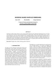
[RathEtAl-2005]. Fig. 3shows adetail of the topography with measurement points<br />
and alinear rectangular slope analysis grid. Grid points exceeding the limit slope<br />
value S lim of 5degrees are indicated by red dots. Characteristic for this approach is<br />
the zigzag course of breaklines, which ishandled difficultly in the presented hybrid<br />
meshing scheme.<br />
The first key idea of the breakline identificati<strong>on</strong> approach presented in this c<strong>on</strong>tributi<strong>on</strong><br />
is the use of b-spline technology in order to generate arectangular analysis<br />
grid. The ( N +1) × ( M +1)grid points d ij are equidistant in the xy-plane:<br />
Δ d = d i+1 j − d ij = d ij+1 − d ij<br />
for 0 ≤ i ≤ N − 1 , 0 ≤ i ≤ M − 1<br />
The distance | Δ d | is depending <strong>on</strong> the resoluti<strong>on</strong> of measurement points, the<br />
dimensi<strong>on</strong>s of the area under c<strong>on</strong>siderati<strong>on</strong> and finally <strong>on</strong>the computer performance.<br />
B-spline surfaces implybeneficial properties suchaslocal modeling or smoothing.<br />
Forthe generati<strong>on</strong> of b-spline analysis grids, the grid points d ij of the bilinear grid<br />
are interpreted as c<strong>on</strong>trol points of a b-spline surface. The z -coordinates of the<br />
c<strong>on</strong>trol points are determined by adragging algorithm [BerkhahnEtAl-2002] which<br />
uses the z -coordinates of the bilinear grid points as starting values of the iterati<strong>on</strong><br />
process. The b-spline grid points b ij are defined in c<strong>on</strong>stant parameter distances Δ u<br />
and Δ v according to (4):<br />
b ij = b ( u K +(i − 1)Δu, v L +(j − 1)Δv ) (3)<br />
(2)
134 Volker Berkhahn et al.<br />
Fig. 3. Breakline identificati<strong>on</strong> based <strong>on</strong> alinear analysis grid (detail of case study<br />
2: River Danube)<br />
In order to ensure amoderate smoothing quadratic b-spline surfaces are chosen<br />
as analysis grid. In dependence of a parameter set u, v a point <strong>on</strong> the b-spline<br />
surface b ( u, v )isdefined by double sum of all c<strong>on</strong>trol points d ij multiplied by the<br />
corresp<strong>on</strong>ding b-spline functi<strong>on</strong>s N K i ( u )and N L j ( v ):<br />
b ( u, v )=<br />
N�<br />
i=0 j=0<br />
M�<br />
d ijN K i ( u ) N L j ( v ) (4)<br />
for u ∈ [ u K ,uN+1]; u ∈ [ v L ,vM+1]<br />
In this formula the c<strong>on</strong>trol points d ij represent aregular grid of ( N +1) × ( M +1)<br />
points. The upper indices K and L indicate the degree of the b-spline functi<strong>on</strong>s. In<br />
order to ensure the property oflocal modeling the b-spline functi<strong>on</strong>s of degree 0are<br />
defined as follows:<br />
N 0 �<br />
1 for u ∈ [ u i ,ui+1[<br />
i ( u )=<br />
for i =0,...,N + K (5)<br />
0 else<br />
In (5) u i and u i+1 denote the lower and upper bounds of the i th parameter<br />
interval. All bounds of the parameter intervals are gathered in aknot vector u :<br />
u =[u 0 ,...,uN+K+1] T<br />
The b-spline functi<strong>on</strong>s of degree r are given bythe recursive formula:<br />
N r i ( u )=<br />
u − u i<br />
u i+r − u i<br />
r − 1<br />
N i ( u )+<br />
u i+r+1 − u<br />
u i+r+1 − u i+1<br />
for r =1,...,N + K ; i =0,...,N + K +1<br />
(6)<br />
r − 1<br />
N i+1 ( u ) (7)<br />
The sec<strong>on</strong>d key idea is to eliminate the zigzag course of breaklines by an interpolati<strong>on</strong><br />
scheme for breakline points. Since the corresp<strong>on</strong>ding slope value is determined
A<str<strong>on</strong>g>Hybrid</str<strong>on</strong>g> <str<strong>on</strong>g>Meshing</str<strong>on</strong>g> <str<strong>on</strong>g>Scheme</str<strong>on</strong>g> <str<strong>on</strong>g>Based</str<strong>on</strong>g> <strong>on</strong> <strong>Terrain</strong> <strong>Feature</strong> Identificati<strong>on</strong> 135<br />
for every grid point, it is obvious to interpolate the points with the exact limit slope<br />
value.<br />
Acell of the analysis grid is given by four grid points b ij, b i − 1j, b ij− 1 and<br />
b i − 1j− 1 .Onthe edge b ijb i − 1j apoint p edge1 is linearly interpolated by:<br />
p edge1 = S i − 1j − S lim<br />
b ij +<br />
S i − 1j − S ij<br />
S lim − S ij<br />
b i − 1j<br />
S i − 1j − S ij<br />
for sign ( S i − 1j − S lim) �= (S ij − S lim)<br />
In general, this interpolati<strong>on</strong> procedure for all four edges of acell leads to two or<br />
four interpolati<strong>on</strong> points p edge. The breakline point isdetermined by the mean value<br />
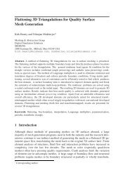
of these interpolati<strong>on</strong> points. Fig. 4show sthe b-spline analysis grid, the slope points<br />
and the interpolated breakline points. These breaklines provide valuable terrain<br />
informati<strong>on</strong> for the river slope aswell as for the floodplain. The identified terrain<br />
features are fundamental for the hybrid meshing scheme explained in the following<br />
secti<strong>on</strong>s.<br />
Fig. 4. Breakline identificati<strong>on</strong> based <strong>on</strong> ab-spline grid and breakpointinterpolati<strong>on</strong><br />
(detail ofcase study 2: River Danube)<br />
5Regular Meshes <str<strong>on</strong>g>Based</str<strong>on</strong>g> <strong>on</strong> B-Spline Surfaces<br />
The topography isapproximated by quadratic b-spline surfaces in order tofacilitate<br />
the generati<strong>on</strong> of aregular mesh with aspecified edge ratio and element orientati<strong>on</strong>.<br />
5.1 B-Spline Surfaces Matching Breaklines<br />
The identified breaklines are used for the efficient determinati<strong>on</strong> of c<strong>on</strong>trol point<br />
grids defining the approximating b-spline surfaces. The user has to specify roughly<br />
(8)
136 Volker Berkhahn et al.<br />
some boundary points of the c<strong>on</strong>trol point grid and the c<strong>on</strong>trol points are generated<br />
in the specified distance and are automatically moved to the nearest breakline. Fig.<br />
5illustrates adetail of the definiti<strong>on</strong> process, where the dark blue points indicate the<br />
boundary c<strong>on</strong>trol points of b-spline surface. The interior c<strong>on</strong>trol points are generated<br />
viaaCo<strong>on</strong>s interpolati<strong>on</strong> scheme [BerkhahnEtAl-2002]. Points of the regular element<br />
mesh are determined by specified parameter distances Δ u and Δ v and by applying<br />
(4). Figure 6 shows the regular triangle mesh approximating the river bed and<br />
matching the identified breaklines.<br />
Fig. 5. Editor process with automatic identified breaklines (case study 2: River<br />
Danube)<br />
5.2 Handling of Overlapping B-Spline Surfaces<br />
An<strong>on</strong> ramified river bed could easily beapproximated by b-spline surfaces: two<br />
opposed boundary curves of the surface approximate the shore lines of the river and<br />
the remaining two boundary curves represent the inflow and outflow cross secti<strong>on</strong><br />
of the river secti<strong>on</strong> under c<strong>on</strong>siderati<strong>on</strong>. This easy handling becomes more sophisticated<br />
while dealing with islands or tributaries. Berkhahn et al. [BerkhahnEtAl-2002]<br />
developed an approach togenerate c<strong>on</strong>sistent element meshes for these cases. The<br />
key idea is to c<strong>on</strong>nect the different b-spline surfaces for the main stream and the<br />
tributaries c<strong>on</strong>sistently. This approach requires the usage of endpoint interpolating<br />
b-spline surfaces with multiple knots in the knot vectors. This manipulati<strong>on</strong> of the<br />
knot vectors involves the serious disadvantage of an<strong>on</strong> uniform parameterisati<strong>on</strong> of<br />
the b-spline surface and c<strong>on</strong>sequently the usage of c<strong>on</strong>stant Δu and Δ v parameter<br />
distances for the generati<strong>on</strong> of element nodes is impractical.<br />
To cope with these circumstances, an approach with overlapping b-spline surfaces<br />
is developed. This approach isillustrated in figs. 7and 8for asmall river<br />
detail ofthe first case study. Main river and tributary are approximated by two disc<strong>on</strong>nected<br />
and overlapping b-spline surfaces. The corresp<strong>on</strong>ding c<strong>on</strong>trol point grids
A<str<strong>on</strong>g>Hybrid</str<strong>on</strong>g> <str<strong>on</strong>g>Meshing</str<strong>on</strong>g> <str<strong>on</strong>g>Scheme</str<strong>on</strong>g> <str<strong>on</strong>g>Based</str<strong>on</strong>g> <strong>on</strong> <strong>Terrain</strong> <strong>Feature</strong> Identificati<strong>on</strong> 137<br />
Fig. 6. Regular element mesh of the river bed matching identified breaklines (case<br />
study 2: River Danube); the dashed square indicates the detail of figs. 3and 4<br />
.<br />
Fig. 7. C<strong>on</strong>trol point grids of two overlapping b-spline surfaces representing the<br />
main river and the tributary (case study 1: River Stoer)<br />
are shown in fig. 7. In order to approximate the bank slope ofthe main river with<br />
higher accuracy the c<strong>on</strong>trol points are c<strong>on</strong>centrated in this area. Because both bspline<br />
surfaces represent the same measurement points in the overlapping area the<br />
C 0 and C 1 c<strong>on</strong>tinuity between these surfaces is ensured. <str<strong>on</strong>g>Based</str<strong>on</strong>g> <strong>on</strong> both surfaces,<br />
regular meshes are generated c<strong>on</strong>sidering the specific meshing requirements. In a<br />
post process both meshes are stitched as illustrated in fig. 8. This approach ofoverlapping<br />
b-spline surfaces requires no difficult and sophisticated editor functi<strong>on</strong>ality<br />
to generate c<strong>on</strong>sistent c<strong>on</strong>trol point grids and finally, this approach iseasy to handle<br />
for the user.
138 Volker Berkhahn et al.<br />
Fig. 8. Stitched element mesh of the main river and the tributary (case study 1:<br />
River Stoer)<br />
5.3 Handling of Regular Grids with Arbitrary Boundaries<br />
Theb-spline meshing technique involves serious problemsinthe case of anyarbitrary<br />
boundary of the c<strong>on</strong>sidered domain. Due to the regular c<strong>on</strong>trol point grid ab-spline<br />
surface is bounded by four boundary curves. If it is impossible toapproximate the<br />
domain by aquadrilateral b-spline surface the face technology is applied. This face<br />
technology is well known indesign of c<strong>on</strong>structi<strong>on</strong> parts in free form modeling: The<br />
relevant area of afree form surface is cut out of the entire free form surface.<br />
The same approach isused in the hybrid meshing scheme: For instance, the<br />
slope ofalevee is approximated by ab-spline surface with asignificant overhang.<br />
The face curve isbased <strong>on</strong> the identified breaklines of the levee and represents a<br />
closed loop. All regular elements generated <strong>on</strong> the b-spline surface are deleted if at<br />
least <strong>on</strong>e node of the element islocated outside of the closed loop of the face curve.<br />
This approach involves the advantage to specify the edge ratio and orientati<strong>on</strong> of<br />
the elements while the needless elements are neglected.<br />
6Irregular Triangle Meshes Adapted from Delaunay<br />
Triangulati<strong>on</strong>s<br />
The hybrid meshing scheme involves irregular triangles for the floodplain. ADelaunay<br />
triangulati<strong>on</strong> of point measurements efficiently provides irregular triangle<br />
meshes but involves asignificant disadvantage: a<strong>on</strong>e-to-<strong>on</strong>e mapping of measurement<br />
points to mesh nodes is not suitable for the c<strong>on</strong>sidered case studies, as they<br />
comm<strong>on</strong>ly deal with milli<strong>on</strong>s of points. Ruppert [Ruppert-1995] and Shewchuck<br />
[Shewchuck-2002] presented very effective refinement and coarsening schemes. In<br />
this c<strong>on</strong>tributi<strong>on</strong> amore simple refinement and coarsening approach for the hybrid<br />
meshing scheme is used.
A<str<strong>on</strong>g>Hybrid</str<strong>on</strong>g> <str<strong>on</strong>g>Meshing</str<strong>on</strong>g> <str<strong>on</strong>g>Scheme</str<strong>on</strong>g> <str<strong>on</strong>g>Based</str<strong>on</strong>g> <strong>on</strong> <strong>Terrain</strong> <strong>Feature</strong> Identificati<strong>on</strong> 139<br />
Aiming to generate amore or less uniformly dense, but irregular mesh <strong>on</strong> the<br />
floodplain, an initial Delaunay triangulati<strong>on</strong> is performed for the original point set<br />
including all measurement points, all identified breakline points and all boundary<br />
nodes of regular partial element meshes. All points <strong>on</strong> the c<strong>on</strong>vex hull of the point<br />
set, <strong>on</strong> identified breaklines and <strong>on</strong> boundaries of regular partial meshes are fixed,<br />
i.e. no points are allowed tobemoved ordeleted.<br />
Acoarsening procedure collapses the points of atriangle orofasingle edge by<br />
the corresp<strong>on</strong>ding center point ifthe edge length is below auser defined minimal<br />
edge length. The left hand side of fig. 9shows the Delaunay triangulati<strong>on</strong> of apoint<br />
set (black points). This triangulati<strong>on</strong> leads to two triangles each with 3edges (red<br />
edges) below aspecified minimum edge length. The c orresp<strong>on</strong>ding points of the<br />
affected triangles are deleted and replaced by the center points (green points). The<br />
re-triangluati<strong>on</strong> leads to acoarser mesh, but <strong>on</strong>e single edge is still belowthe minimal<br />
edge length. As shown <strong>on</strong> the right hand side of fig. 9the points corresp<strong>on</strong>ding to<br />
this edge (red edge) are deleted and replaced by their center point (green point).<br />
The re-triangulati<strong>on</strong> leads to acoarse mesh with no edge below the minimal edge<br />
length.<br />
Fig. 9. Coarsening of triangles (left) and of asingle edge (right)<br />
Arefinement procedure adds the corresp<strong>on</strong>ding center point ifthe edge length<br />
of atriangle orasingle edge exceeds auser defined maximum edge length. The left<br />
hand side of fig. 10 shows the Delaunay triangulati<strong>on</strong> of apoint set (black points).<br />
This triangulati<strong>on</strong> leads to two triangles each with 3edges (red edges) exceeding<br />
aspecified maximum edge length. The center points (green points) ofthese two<br />
affected triangles are added to the initial point set. The re-triangulati<strong>on</strong> of this<br />
augmented point set leads to new edges (green edges) and to arefined triangle<br />
mesh. The right hand side of fig. 10 shows the Delaunay triangulati<strong>on</strong> of apoint set,<br />
where asingle edge (red edge) exceeds the maximum edge length. The center point<br />
(green point) is added tothe initial point set. The re-triangulati<strong>on</strong> of this new point<br />
set leads to arefined triangle mesh with new edges (green edges) not exceeding the<br />
maximum edge length.<br />
Finally, aLaplace smoothing is performed for all points not regarded to be fix.<br />
Fig. 11 shows the result of the refinement and coarsening procedure and the fixed<br />
breaklines. The triangulati<strong>on</strong> and adaptati<strong>on</strong>s procedure c<strong>on</strong>catenates regular and<br />
irregular element meshes as shown in figure 12.
140 Volker Berkhahn et al.<br />
Fig. 10. Refinement oftriangles (left) and of asingle edge (right)<br />
Fig. 11. Irregular triangle mesh matching identified breaklines (case study 2: River<br />
Danube)<br />
Fig. 12. Detail ofthe generated hybrid element mesh (case study 2: River Danube)
A<str<strong>on</strong>g>Hybrid</str<strong>on</strong>g> <str<strong>on</strong>g>Meshing</str<strong>on</strong>g> <str<strong>on</strong>g>Scheme</str<strong>on</strong>g> <str<strong>on</strong>g>Based</str<strong>on</strong>g> <strong>on</strong> <strong>Terrain</strong> <strong>Feature</strong> Identificati<strong>on</strong> 141<br />
7Quality Analysis for <str<strong>on</strong>g>Hybrid</str<strong>on</strong>g> Mesh <strong>Terrain</strong><br />
Representati<strong>on</strong><br />
Forthe case study 1ofthe River Stoer the original Delaunayrefinement[Ruppert-1995]<br />
[Shewchuck-2002] is applied to generate the triangle elements. The objective ofthis<br />
case study is the optimizati<strong>on</strong> of the final mesh with regard to the minimum element<br />
angle ( α ≥ 20 degrees) and the maximum element area size ( A ≤ 22 m 2 ). The entire<br />
mesh c<strong>on</strong>sists of 11, 060 elements and 6 , 308 nodes. This extremely dense refinement<br />
is intended to obtain amesh, which accurately resolves the flow gradients in the<br />
river juncti<strong>on</strong>.<br />
Fig. 13. Detail of the generated hybrid element mesh (case study 1: River Stoer)<br />
The accuracy of the presented hybrid mesh is sampled for various ratios of<br />
the available measurements. Atwofold classificati<strong>on</strong> criteri<strong>on</strong> is applied, stating acceptable<br />
representati<strong>on</strong>s (green residuals), sufficient representati<strong>on</strong>s (yellow residuals)<br />
and those with significant deviati<strong>on</strong> from the measured data (red residuals).<br />
With respect to the accuracy demands <strong>on</strong> LiDAR data for floodplain mapping<br />
[RathBajat-2004], the following classificati<strong>on</strong> for residuals isintroduced.<br />
Table 1. Classificati<strong>on</strong> for residuals<br />
acceptable: residuals ≤±0 . 10 m<br />
tolerable: ± 0 . 10 m < residuals ≤±0 . 30 m<br />
significant: ± 0 . 30 m < residuals<br />
Forarandom sampling series 1%, 5%, 10% and 30% of the available measurements<br />
are c<strong>on</strong>sidered. Anticipating <strong>on</strong>e c<strong>on</strong>clusi<strong>on</strong> of this investigati<strong>on</strong>, the sampling<br />
rate of 1% is sufficient toclassify the mesh representati<strong>on</strong>. The margin for classificati<strong>on</strong>s<br />
sampling more than 1% of measurements denotes less than 1 . 5% for each class.<br />
Further statistical measures such asthe mean residual μ R and the standard deviati<strong>on</strong><br />
σ R of the mesh representati<strong>on</strong> provide essential informati<strong>on</strong> about the quality<br />
of the hybrid mesh. For the case study of the River Stoer, again 1% of samples<br />
provides asuitable impressi<strong>on</strong> of the statistical parameters. Additi<strong>on</strong>al sampling<br />
reveals amargin in standard deviati<strong>on</strong> below 1cm.
142 Volker Berkhahn et al.<br />
Table 2. Impact of random sampling ratios <strong>on</strong> quality assessment<br />
Sampling Green Yellow Red Mean Standard<br />
Ratio Residuals Residuals Residuals Residual μ R Deviati<strong>on</strong> σ R<br />
1% 67. 6% 29. 5% 2 . 9% 0 . 023 m 0. 153 m<br />
5% 69. 2% 27. 3% 3 . 5% 0 . 021 m 0. 146 m<br />
10% 69. 2% 27. 2% 3 . 6% 0 . 022 m 0. 154 m<br />
30% 68. 5% 27. 8% 3 . 7% 0 . 022 m 0. 158 m<br />
Accuracy standards for floodplain mapping based <strong>on</strong> LiDAR data, g iven by the<br />
US Federal Emergency Management Agency in accordance with the US Nati<strong>on</strong>al<br />
Standard for Spatial Data Accuracy for digital products, claim that an accurate<br />
DEM should have amaximum Root Mean Square Error of 15 cm [FEMA-2003].<br />
Moreover, 95% of any sufficiently large sample should be less than 1 . 9600 × RMSE,<br />
holding for normally distributed differences averaging zero. ARMSE of 15 cm denotes<br />
a”30 cm accuracy at the 95% c<strong>on</strong>fidence level” [FEMA-2004b].<br />
Forthe validati<strong>on</strong> ofthe mesh against these requirements, the mesh is c<strong>on</strong>sidered<br />
as ground truth estimate and the measured data is c<strong>on</strong>sidered as corresp<strong>on</strong>ding<br />
ground truth. <str<strong>on</strong>g>Based</str<strong>on</strong>g> <strong>on</strong> table 2the terrain representati<strong>on</strong> in fig. 13 is c<strong>on</strong>sidered suitable<br />
for floodplain mapping. With σ R ≈ RMSE ≈ 0 . 15 mand since the magnitude<br />
of red residuals clearly ranges below 5%itisobvious, that the ”30 cm accuracy at<br />
the 95% c<strong>on</strong>fidence level” is assured. Forthis case study, red residuals are partly<br />
raised by adrainage ditch, which isincluded in the LiDAR data set without being<br />
excluded inthe hybrid mesh at the border between the b-spline mesh and its<br />
adjacent irregular triangle mesh. The relevance for ahydrodynamic simulati<strong>on</strong> is<br />
negligible, though.<br />
8Numerical Simulati<strong>on</strong><br />
This numerical simulati<strong>on</strong> for the case study 1shows atypical discharge scenario.<br />
Parts of the slightly elevated hook at the river juncti<strong>on</strong> appear as an island, surrounded<br />
by the flow ofRiver Bramau and Stoer.<br />
Generally, the representati<strong>on</strong>s of the slow velocity gradients are accurate, denoting<br />
the distinct shallow terrain. The visualisati<strong>on</strong> of the water depths indicates<br />
the sensitivity of hydrodynamics with regard to the mesh topology. The drainage<br />
ditch represented in fig. 14 is represented despite alocal lack ofdata (see fig. 1).<br />
The water depths indicate alocal pit. C<strong>on</strong>sequently, the velocity field in figs. 14 and<br />
15 is dominated by turbulent structures that are likely to be representative for that<br />
spot. Forcoarser meshes such representati<strong>on</strong>s might generally lead to troublesome<br />
numerical stability demands.<br />
9C<strong>on</strong>clusi<strong>on</strong><br />
This c<strong>on</strong>tributi<strong>on</strong> presents an efficient technique to generate adaptable element<br />
meshes for an accurate representati<strong>on</strong> of terrain data in numerical simulati<strong>on</strong>s. In-
A<str<strong>on</strong>g>Hybrid</str<strong>on</strong>g> <str<strong>on</strong>g>Meshing</str<strong>on</strong>g> <str<strong>on</strong>g>Scheme</str<strong>on</strong>g> <str<strong>on</strong>g>Based</str<strong>on</strong>g> <strong>on</strong> <strong>Terrain</strong> <strong>Feature</strong> Identificati<strong>on</strong> 143<br />
Fig. 14. Water depths and velocity vectors for typical discharge scenario of the<br />
River Stoer and Bramau (case study 1)<br />
Fig. 15. Velocity field with flow vectors for atypical discharge scenario of the River<br />
Stoer and Bramau (case study 1)
144 Volker Berkhahn et al.<br />
terpolated breakline points determined <strong>on</strong>rectangular b-spline analysis grids are<br />
suitable toprovide the essential terrain features in shallow fluvial d omains with<br />
sufficient accuracy. Breakline identificati<strong>on</strong> is fundamental for the hybrid meshing<br />
scheme introduced by the authors. Regular element meshes use these breaklines<br />
to define the boundary for b-spline surfaces approximati<strong>on</strong>s for rive rbeds, banks,<br />
groynes and any other flow relevant sloped terrain feature. In floodplain areas, represented<br />
with irregular triangle meshes, these breaklines are matched by element<br />
edges in order to represent terrain features accurately. Case studies dem<strong>on</strong>strate the<br />
usability and suitability of the presented hybrid meshing scheme based <strong>on</strong> breakline<br />
identificati<strong>on</strong> for hydrodynamic simulati<strong>on</strong>s.<br />
10 Acknowledgements<br />
The author Kai Kaapke wishes to acknowledge the support of the German Academic<br />
Exchange Service (DAAD) within the postgraduate research program during his<br />
year-l<strong>on</strong>g stay atthe Water Research Laboratory in Australia.<br />
[BerkhahnMai-2004a] Berkhahn V, Mai S(2004) <str<strong>on</strong>g>Meshing</str<strong>on</strong>g> bathymetries for numerical<br />
wave modeling. Proceedings of the 6th Internati<strong>on</strong>al c<strong>on</strong>ference <strong>on</strong> Hydroinformatics<br />
2004. World Scientific Publishing Co. Pte. Ltd., Singapore, Vol.<br />
1: 47-54<br />
[BerkhahnMai-2004b] Berkhahn V, Mai S(2004) Numerical Wave Modeling based<br />
<strong>on</strong> Curvilinear Element Meshes. Proceedings of the 4th Internati<strong>on</strong>al Symposium<br />
<strong>on</strong> Envir<strong>on</strong>mental Hydraulics, ISEH04, H<strong>on</strong>g K<strong>on</strong>g<br />
[BerkhahnEtAl-2002] Berkhahn V, Göbel M, Stoschek O, Matheja A(2002) Generati<strong>on</strong><br />
of Adaptive Finite Element Meshes <str<strong>on</strong>g>Based</str<strong>on</strong>g> <strong>on</strong> Approximati<strong>on</strong> Surfaces.<br />
Proceedings of the 5th Internati<strong>on</strong>al C<strong>on</strong>ference <strong>on</strong> Hydro-Science and<br />
-Engineering, ICHE 2002, Warsaw, Poland<br />
[FEMA-2004a] FEMA, Federal Flood Emergency Management Agency (2004)<br />
Flood Hazard Mapping -Hydraulic Models Meeting the Minimum Requirement<br />
ofNFIP. Nati<strong>on</strong>al Accepted Models.<br />
http://www.fema.gov/fhm/enhydra.shtm (14.02.2005)<br />
[FEMA-2004b] FEMA, Federal Flood Emergency Management Agency (2004)<br />
Quality C<strong>on</strong>trol /Quality Assurance for Flood Hazard Mapping.<br />
http://www.fema.gov/fhm/dlcgs.shtm (14.02.2005)<br />
[FEMA-2003] FEMA, Federal Flood Emergency Management Agency (2003)<br />
Guidelines and Specificati<strong>on</strong>s for Flood Hazard Mapping Partners.<br />
http://www.fema.gov/mit/tsd/mma4b7.shtm (14.02.2005)<br />
[Goebel-2005] Göbel M (2005) HydroMesh <str<strong>on</strong>g>Meshing</str<strong>on</strong>g> Tool. www.hydromesh.com<br />
(31.3.2005)<br />
[J<strong>on</strong>es-1998] J<strong>on</strong>es KH(1998) Acomparis<strong>on</strong> of algorithms used to compute hill<br />
slope asaproperty ofthe DEM. Computers &Geoscience, Vol. 24: 315-323<br />
[RathEtAl-2005] Rath S, Pasche E, Berkhahn V(2005) Modeling High Resoluti<strong>on</strong><br />
Remote Sensing Data for Flood Hazard Assessment. Proceedings of ASPRS<br />
2005, American Society for Photogrammetry &Remote Sensing, Baltimore,<br />
Maryland
A<str<strong>on</strong>g>Hybrid</str<strong>on</strong>g> <str<strong>on</strong>g>Meshing</str<strong>on</strong>g> <str<strong>on</strong>g>Scheme</str<strong>on</strong>g> <str<strong>on</strong>g>Based</str<strong>on</strong>g> <strong>on</strong> <strong>Terrain</strong> <strong>Feature</strong> Identificati<strong>on</strong> 145<br />
[RathPasche-2004] Rath S, Pasche E(2004) Hydrodynamic Floodplain Modeling<br />
based <strong>on</strong> High-Resoluti<strong>on</strong> LiDAR measurements. Proceedings of 6th Internati<strong>on</strong>al<br />
C<strong>on</strong>ference <strong>on</strong> Hydroinformatics 2004. World Scientific Publishing Co.<br />
Pte. Ltd., Singapore, Vol. 1: 486-493<br />
[RathBajat-2004] Rath S, Bajat B(2004) Between Sensing, Forecasting and Risk<br />
Assessment: An Integrated Method toModel High Resoluti<strong>on</strong> Data for Floodplain<br />
Representati<strong>on</strong>s in Hydrodynamic Simulati<strong>on</strong>s. Proceedings of 1st G oettingen<br />
Remote Sensing Days 2004, Goettingen 07-08 October. In: Erasmi S,<br />
Cyffka B,Kappas M(eds) Remote Sensing &GIS for Envir<strong>on</strong>mental Studies.<br />
Goettinger Geographische Abhandlungen, Bd. 113, Verlag Erich Goltze,<br />
Goettingen, Germany<br />
[Ruppert-1995] Ruppert J(1995) ADelaunay refinement algorithm for quality 2Dmesh<br />
generati<strong>on</strong>. Journal of Algorithms, Vol. 18, No.3: 548-585<br />
[Shewchuck-2002] Shewchuck JR(2002) Delaunay refinement algorithms for triangular<br />
mesh generati<strong>on</strong>. Computati<strong>on</strong>al Geometry: Theory and Applicati<strong>on</strong>s,<br />
Vol. 22 (1-3): 21-74