Leakage Test System LTS 670 - Dr. Wiesner
Leakage Test System LTS 670 - Dr. Wiesner
Leakage Test System LTS 670 - Dr. Wiesner

You also want an ePaper? Increase the reach of your titles
YUMPU automatically turns print PDFs into web optimized ePapers that Google loves.
<strong>Leakage</strong> <strong>Test</strong> <strong>System</strong> <strong>LTS</strong> <strong>670</strong><br />
Technical Information page 1<br />
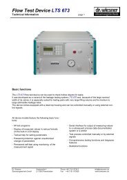
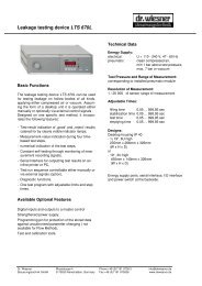
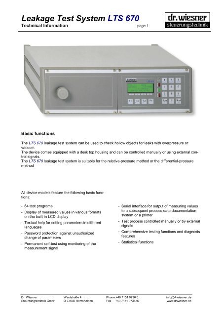
Basic functions<br />
The <strong>LTS</strong> <strong>670</strong> leakage test system can be used to check hollow objects for leaks with overpressure or<br />
vacuum.<br />
The device comes equipped with a desk top housing and can be controlled manually or using external control<br />
signals.<br />
The <strong>LTS</strong> <strong>670</strong> leakage test system is suitable for the relative-pressure method or the differential-pressure<br />
method<br />
All device models feature the following basic functions:<br />
- 64 test programs<br />
- Display of measured values in various formats<br />
on the built-in LCD display<br />
- Textual help for setting parameters in different<br />
languages<br />
- Password protection against unauthorized<br />
change of parameters<br />
- Permanent self-test using monitoring of the<br />
measurement signal<br />
- Serial interface for output of measuring values<br />
to a subsequent process data documentation<br />
system or a printer<br />
- <strong>Test</strong> process controlled manually or by external<br />
signals<br />
- Comprehensive testing functions and diagnosis<br />
features<br />
- Statistical functions<br />
<strong>Dr</strong>. <strong>Wiesner</strong> Weststraße 4 Phone +49 7151 9736 0 info@drwiesner.de<br />
Steuerungstechnik GmbH D-73630 Remshalden Fax +49 7151 973636 www.drwiesner.de
<strong>Leakage</strong> <strong>Test</strong> <strong>System</strong> <strong>LTS</strong> <strong>670</strong><br />
Technical Information page 2<br />
<strong>Test</strong>ing<br />
<strong>Test</strong>ing method<br />
The device operates according to the relativepressure<br />
method or the differential-pressure<br />
method.<br />
Relative-pressure method:<br />
Applying this method, the test specimen is filled<br />
with a predetermined pressure. After the filling<br />
time has elapsed, the test volume is sealed off.<br />
Following a stabilization time, during which temperature<br />
equalization takes place between the test<br />
specimen, testing equipment and test medium,<br />
actual testing commences. If the test specimen is<br />
leak, the pressure in the test volume will begin to<br />
fall. The difference in pressure is measured between<br />
the beginning and end of the test period<br />
and is subjected to rating.<br />
Applying this method, use is made of piezoresistive<br />
pressure sensors, whose range of measurement<br />
corresponds to the test-pressure range. This<br />
method is highly suitable for detecting minor to<br />
medium-sized leakages.<br />
Differential-pressure method:<br />
Applying this method the test specimen and a<br />
tight reference volume are filled with equal pressure.<br />
Afterwards they are both sealed off separately.<br />
After a stabilization time has elapsed, during<br />
which temperature equalization takes place<br />
between the test specimen, testing equipment and<br />
test medium, the actual process of testing commences.<br />
If the test specimen is leak, this will result<br />
in a difference in pressure between the test<br />
specimen and the reference volume, this then<br />
being measured and subjected to rating.<br />
Applying this method, use can be made of pressure<br />
sensors geared to a maximum accuracy<br />
regardless of the test pressure selected. This<br />
method is highly suitable for detecting minor leakages.<br />
<strong>Test</strong> procedure<br />
- Select existing test program or enter new time<br />
and limit values.<br />
- Start by pressing the “Start” button on the front<br />
panel or by sending an external control signal.<br />
- Pre-filling (if installed)<br />
- Filling (time- or pressure controlled)<br />
- Stabilization<br />
- <strong>Test</strong>ing<br />
- Evaluation<br />
<strong>Test</strong> result “NOK” must be acknowledged by<br />
pressing the “Stop” button; if test result is “OK”,<br />
the procedure is continued by<br />
- Emptying<br />
By pressing the “Stop” button, the test routine can<br />
be stopped at any step. In this state, the display of<br />
the remaining time switches to negative time so<br />
that the duration of the interruption can be determined<br />
at any time. Press the “Start” button to continue<br />
the test run. Press the “Stop” button twice to<br />
terminate the test.<br />
Display during test<br />
During each test step, various textual information<br />
will be displayed.<br />
Before start:<br />
<strong>Test</strong> program and the state of the integrated statistics<br />
counters in the upper rows, result and<br />
measured value of the last test in the lower rows.<br />
In the filling step:<br />
<strong>Test</strong> program and the state of the integrated statistics<br />
counters in the upper rows, text “Filling”,<br />
display of remaining time, and measured value of<br />
the test pressure monitoring in the lower rows.<br />
In the stabilization step:<br />
<strong>Test</strong> program and the state of the integrated statistics<br />
counters in the upper rows, text “Damping”,<br />
display of remaining time, and measured value of<br />
the test pressure monitoring in the lower rows.<br />
In the test step:<br />
<strong>Test</strong> program and the state of the integrated statistics<br />
counters in the upper rows, text “Damping”,<br />
display of remaining time, and measured value of<br />
the flow rate in the lower rows.<br />
In the emptying step:<br />
<strong>Test</strong> program and the state of the integrated statistics<br />
counters in the upper row, text “<strong>Test</strong>ing”,<br />
test result, and measured value of the flow rate in<br />
the lower rows.<br />
<strong>Test</strong> results<br />
- Red LED “>” is on, output “NOK” is set.<br />
Measured value at the end of test time exceeds<br />
upper limit value.<br />
- Red LED “
<strong>Leakage</strong> <strong>Test</strong> <strong>System</strong> <strong>LTS</strong> <strong>670</strong><br />
Technical Information page 3<br />
Interfaces<br />
Interface to external control<br />
The plug of the electrical part of the standard test<br />
device is assigned as follows:<br />
Inputs:<br />
Start<br />
Stop/Interruption<br />
<strong>Test</strong> program bit 0<br />
<strong>Test</strong> program bit 1<br />
<strong>Test</strong> program bit 2<br />
<strong>Test</strong> program bit 3<br />
<strong>Test</strong> program bit 4<br />
<strong>Test</strong> program bit 5<br />
Outputs:<br />
Ready<br />
<strong>Test</strong> running<br />
Pause<br />
<strong>Test</strong> result OK<br />
<strong>Test</strong> result NOK<br />
<strong>Test</strong> finished<br />
Mark OK part<br />
Signal end of test<br />
Error<br />
Pre-filling<br />
Voltage:<br />
+ 24 V Power output for external opto coupler<br />
or relay with potential-free input<br />
0 V Input as reference potential for the test<br />
device outputs.<br />
The test device outputs and the 24V voltage output<br />
can be loaded with 0.5 A each. However, the<br />
overall load in the basic device must<br />
not exceed 2.5 A. A stronger power supply is<br />
available upon request.<br />
Serial interface<br />
After the completion of each test, a character<br />
string is transmitted containing the test result, the<br />
measured value, and the test program.<br />
The output of date and time, and test pressure<br />
can be switched on and off.<br />
Statistics<br />
The statistics menu shows the following<br />
information:<br />
Total Number Percent<br />
NOK Number Percent<br />
OK Number Percent<br />
NOK total Number Percent<br />
Fine leak Number Percent<br />
Rough/Wrong Number Percent<br />
OK results<br />
minimum Value<br />
maximum Value<br />
mean value Value<br />
<strong>Dr</strong>. <strong>Wiesner</strong> Weststraße 4 Phone +49 7151 9736 0 info@drwiesner.de<br />
Steuerungstechnik GmbH D-73630 Remshalden Fax +49 7151 973636 www.drwiesner.de
<strong>Leakage</strong> <strong>Test</strong> <strong>System</strong> <strong>LTS</strong> <strong>670</strong><br />
Technical Information page 4<br />
Technical data<br />
Supply:<br />
electrical: U = 230 V, 50 Hz<br />
pneumatic: clean pressurized air, max. 7 bar<br />
Power rating of the outputs:<br />
individual maximum 0.5 A<br />
total maximum 2.5 A<br />
Stronger power supply is available upon request.<br />
Adjustable times:<br />
Filling time: 0.0 ... 3,000.0 sec<br />
Stabiliz. time: 0.0 ... 3,000.0 sec<br />
<strong>Test</strong> time: 0.0 ... 3,000.0 sec<br />
Emptying time: 0.0 ... 3,000.0 sec<br />
Available pressure ranges:<br />
-1 ... 0 bar<br />
0 ... 1 bar<br />
0 ... 4 bar<br />
0 ... 6 bar<br />
0 ... 10 bar<br />
Measuring ranges:<br />
relative-pressure test:<br />
like pressure range<br />
resolution 1/20000<br />
differential-pressure test:<br />
±20 mbar, resolution 0.2 Pa<br />
Designs:<br />
Desk top housing IP40<br />
19“, 3HE<br />
450mm x 140mm x 326mm<br />
(W x H x D), or<br />
½19“, 6HE<br />
235mm x 266mm x 326mm<br />
(W x H x D)<br />
with separate slots for electrical and pneumatic<br />
parts<br />
Supply connections, interfaces and main switch<br />
on back panel<br />
Serial interface<br />
9600 bps<br />
1 start bit<br />
8 data bit (ASCII characters)<br />
1 stop bit<br />
no parity check<br />
Available options<br />
- two externally selectable test connections<br />
- <strong>Test</strong> start via external switch<br />
- Enforced voltage supply<br />
- <strong>Test</strong> and calibration aids<br />
- Special protocol for serial interface<br />
<strong>Dr</strong>. <strong>Wiesner</strong> Weststraße 4 Phone +49 7151 9736 0 info@drwiesner.de<br />
Steuerungstechnik GmbH D-73630 Remshalden Fax +49 7151 973636 www.drwiesner.de