

V850E/CA4 HELIOS 32- bit RISC Microcontroller uPD70(F)3175 ...
V850E/CA4 HELIOS 32- bit RISC Microcontroller uPD70(F)3175 ...
V850E/CA4 HELIOS 32- bit RISC Microcontroller uPD70(F)3175 ...

You also want an ePaper? Increase the reach of your titles
YUMPU automatically turns print PDFs into web optimized ePapers that Google loves.
Document No. U16242EE1V0DS00<br />
Data Published: July 2003<br />
<strong>V850E</strong>/<strong>CA4</strong> TM <strong>HELIOS</strong><br />
<strong>32</strong>- <strong>bit</strong> <strong>RISC</strong> <strong>Microcontroller</strong><br />
DATA SHEET<br />
MOS INTEGRATED CIRCUIT<br />
µPD70(F)<strong>3175</strong><br />
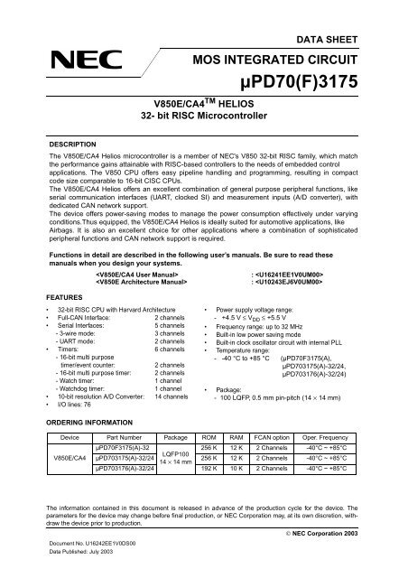
DESCRIPTION<br />
The <strong>V850E</strong>/<strong>CA4</strong> Helios microcontroller is a member of NEC's V850 <strong>32</strong>-<strong>bit</strong> <strong>RISC</strong> family, which match<br />
the performance gains attainable with <strong>RISC</strong>-based controllers to the needs of embedded control<br />
applications. The V850 CPU offers easy pipeline handling and programming, resulting in compact<br />
code size comparable to 16-<strong>bit</strong> CISC CPUs.<br />
The <strong>V850E</strong>/<strong>CA4</strong> Helios offers an excellent combination of general purpose peripheral functions, like<br />
serial communication interfaces (UART, clocked SI) and measurement inputs (A/D converter), with<br />
dedicated CAN network support.<br />
The device offers power-saving modes to manage the power consumption effectively under varying<br />
conditions.Thus equipped, the <strong>V850E</strong>/<strong>CA4</strong> Helios is ideally suited for automotive applications, like<br />
Airbags. It is also an excellent choice for other applications where a combination of sophisticated<br />
peripheral functions and CAN network support is required.<br />
Functions in detail are described in the following user’s manuals. Be sure to read these<br />
manuals when you design your systems.<br />
FEATURES<br />
: <br />
: <br />
• <strong>32</strong>-<strong>bit</strong> <strong>RISC</strong> CPU with Harvard Architecture<br />
Full-CAN Interface: 2 channels<br />
Serial Interfaces: 5 channels<br />
- 3-wire mode: 3 channels<br />
- UART mode: 2 channels<br />
Timers: 6 channels<br />
- 16-<strong>bit</strong> multi purpose<br />
timer/event counter: 2 channels<br />
- 16-<strong>bit</strong> multi purpose timer: 2 channels<br />
- Watch timer: 1 channel<br />
- Watchdog timer: 1 channel<br />
10-<strong>bit</strong> resolution A/D Converter: 14 channels<br />
I/O lines: 76<br />
ORDERING INFORMATION<br />
Power supply voltage range:<br />
- +4.5 V ≤ V DD ≤ +5.5 V<br />
Frequency range: up to <strong>32</strong> MHz<br />
Built-in low power saving mode<br />
Built-in clock oscillator circuit with internal PLL<br />
Temperature range:<br />
- -40 °C to +85 °C (µPD70F<strong>3175</strong>(A),<br />
µPD70<strong>3175</strong>(A)-<strong>32</strong>/24,<br />
µPD703176(A)-<strong>32</strong>/24)<br />
Package:<br />
- 100 LQFP, 0.5 mm pin-pitch (14 × 14 mm)<br />
Device Part Number Package ROM RAM FCAN option Oper. Frequency<br />
<strong>V850E</strong>/<strong>CA4</strong><br />
µPD70F<strong>3175</strong>(A)-<strong>32</strong><br />
256 K 12 K 2 Channels -40°C ~ +85°C<br />
µPD70<strong>3175</strong>(A)-<strong>32</strong>/24<br />
LQFP100<br />
14 × 14 mm<br />
256 K 12 K 2 Channels -40°C ~ +85°C<br />
µPD703176(A)-<strong>32</strong>/24 192 K 10 K 2 Channels -40°C ~ +85°C<br />
The information contained in this document is released in advance of the production cycle for the device. The<br />
parameters for the device may change before final production, or NEC Corporation may, at its own discretion, withdraw<br />
the device prior to production.<br />
© NEC Corporation 2003
µPD70(F)<strong>3175</strong><br />
INTERNAL BLOCK DIAGRAM<br />
Note: The CAN macro of this device fulfils the requirements according ISO 11898. Additionally the<br />
CAN macro was tested according to the test procedures required by ISO 16845. The CAN<br />
macro successfully passed all test patterns. Beyond these test patterns, other tests like<br />
robustness tests and processor interface tests as recommended by C&S/FH Wolfenbuettel<br />
have successfully been issued.<br />
2<br />
NMI<br />
INTP00 to INTP02<br />
INTP10, INTP15<br />
INTP20, INTP25<br />
INTP30, INTP<strong>32</strong>,<br />
INTP34<br />
TIG00 to TIG05<br />
TOG01 to TOG04<br />
TIG10 to TIG15<br />
TOG11 to TOG14<br />
PCL<br />
RXD60<br />
TXD60<br />
RXD61<br />
TXD61<br />
SI00<br />
SO00<br />
SCK00<br />
SI01<br />
SO01<br />
SCK01<br />
SI10<br />
SO10<br />
SCK10<br />
FCRXD0<br />
FCTXD0<br />
FCRXD1<br />
FCTXD1<br />
Interrupt<br />
Controller<br />
16-<strong>bit</strong> Timer<br />
TMG0<br />
16-<strong>bit</strong> Timer<br />
TMG1<br />
16-<strong>bit</strong> Timer<br />
TMD0<br />
16-<strong>bit</strong> Timer<br />
TMD1<br />
Watch<br />
Timer<br />
Watchdog<br />
Timer<br />
PLLDIV<br />
UART60<br />
UART61<br />
CSI00<br />
CSI01<br />
CSI10<br />
FCAN1<br />
FCAN2<br />
Note<br />
Note<br />
P00-P02<br />
P10-P15<br />
ROM<br />
256 K<br />
(Flash<br />
& Mask)<br />
or 192 K<br />
(Mask)<br />
RAM<br />
12 K<br />
(Flash<br />
& Mask)<br />
or 10 K<br />
(Mask)<br />
NPB<br />
Bus<br />
bridge<br />
Ports<br />
PC<br />
<strong>32</strong>-<strong>bit</strong> Barrel<br />
Shifter<br />
System<br />
Registers<br />
General<br />
Registers<br />
<strong>32</strong>-<strong>bit</strong> x <strong>32</strong><br />
DMA<br />
P20-P25<br />
P30-P35<br />
P40-P45<br />
P70-P713<br />
PCD2-PCD3<br />
PCM0-PCM3<br />
PCT0,1,4,6<br />
PDH0-PDH8<br />
PDL0-PDL15<br />
BRG0<br />
CPU<br />
Data Sheet U16242EE1V0DS00<br />
Multiplier<br />
<strong>32</strong> x <strong>32</strong> = 64<br />
A<br />
L<br />
U<br />
Internal Peripheral Bus<br />
10-<strong>bit</strong> ADC<br />
ANI0-ANI13<br />
AV REF<br />
AV SS<br />
AV DD<br />
14 channels<br />
BVDD0 BVSS0 BVDD1 BVSS1 BVDD2 BVSS2 Voltage<br />
Regulator<br />
Voltage<br />
Regulator<br />
V PP(Flash only)<br />
Oscillator and<br />
Clock Generator<br />
System Control<br />
VDD0 VSS0 VSS1 REGC_M0<br />
REGC_M1<br />
CVDD CVSS REGC_0<br />
X1<br />
X2<br />
MODE1<br />
MODE0<br />
RESET
PIN IDENTIFICATION<br />
Data Sheet U16242EE1V0DS00<br />
µPD70(F)<strong>3175</strong><br />
ANI0 to ANI13 Analog Inputs TOG01 to TOG04 Timer G0 Compare Output<br />
AVDD Analog Power Supply TOG11 to TOG14 Timer G1 Compare Output<br />
AVSS Analog Ground TIG00 to TIG05 Timer G0 Capture Input<br />
AVREF Analog reference Voltage supply<br />
TIG10 to TIG15 Timer G1 Capture Input<br />
PCL Processor Clock Output<br />
FCRXD0,<br />
FCRXD1<br />
FCTXD0,<br />
FCTXD1<br />
INTP00, INTP01,<br />
INTP02, INTP10,<br />
INTP15, INPT20,<br />
INTP25, INTP30,<br />
INTP<strong>32</strong>, INTP34<br />
CAN Receive Data for channel<br />
0 and 1<br />
CAN Transmit Data for channel<br />
0 and 1<br />
REGC_M0,<br />
REGC_M1<br />
Main Regulator Output<br />
REGC_O Osc and PLL Regulator Output<br />
MODE0, MODE1 Operation mode select<br />
External Interrupt Input X1, X2 Main System Clock<br />
NMI Non-Maskable Interrupt Input RESET Reset Input<br />
P00 to P02 Port 0 CVDD , CVSS Oscillator and PLL power supply<br />
P10 to P15 Port 1 V DD0<br />
Digital power supply for Flash, CPU<br />
and I/O buffer<br />
P20 to P25 Port 2 VSS0 , VSS1 Digital Ground for Flash, CPU and<br />
I/O buffer<br />
P30 to P35 Port 3 BVSS0 to BVSS2 I/O buffers Ground<br />
P40 to P45 Port 4 BV DD0 to BV DD2 I/O buffers supply<br />
P70 to P713 Port 7 VPP Programming Voltage<br />
PCM0 to PCM3 Port CM<br />
PCT0, PCT1,<br />
PCT4, PCT6<br />
Port CT<br />
PCD2 to PCD3 Port CD<br />
PDL0 to PDL15 Port DL<br />
PDH0 to PDH8 Port DH<br />
RXD60, RXD61 UART Receive Data<br />
TXD60, TXD61 UART Transmission Data<br />
SCK00, SCK01,<br />
SCK10<br />
Synchronous Interface Clock<br />
SI00, SI01, SI10 Synchronous Interface Input<br />
SO00, SO01,<br />
SO10<br />
Synchronous Interface Output<br />
3
4<br />
Data Sheet U16242EE1V0DS00<br />
µPD70(F)<strong>3175</strong><br />
PIN CONFIGURATION<br />
100-Pin Plastic LQFP (0.5 mm pin pitch) (14 × 14 mm)<br />
µPD70F<strong>3175</strong>(A)-<strong>32</strong><br />
µPD70<strong>3175</strong>(A)-<strong>32</strong>/24<br />
µPD703176(A)-<strong>32</strong>/24<br />
AVREF<br />
AVDD<br />
AVSS<br />
P10/TIG00/INTP10<br />
P11/TIG01/TOG01<br />
P12/TIG02/TOG02<br />
P14/TIG04/TOG04/SO10<br />
P70/ANI0<br />
P71/ANI1<br />
P72/ANI2<br />
P76/ANI6<br />
P77/ANI7<br />
P78/ANI8<br />
P79/ANI9<br />
P710/ANI10<br />
P711/ANI11<br />
P712/ANI12<br />
1<br />
2<br />
3<br />
4<br />
5<br />
6<br />
7<br />
8<br />
9<br />
10<br />
11<br />
12<br />
13<br />
14<br />
15<br />
16<br />
17<br />
18<br />
19<br />
20<br />
21<br />
22<br />
23<br />
24<br />
25<br />
26<br />
27<br />
28<br />
29<br />
30<br />
31<br />
<strong>32</strong><br />
33<br />
34<br />
35<br />
36<br />
37<br />
38<br />
39<br />
40<br />
41<br />
42<br />
43<br />
44<br />
45<br />
75<br />
74<br />
73<br />
72<br />
71<br />
70<br />
69<br />
68<br />
67<br />
66<br />
65<br />
64<br />
63<br />
62<br />
61<br />
60<br />
59<br />
58<br />
57<br />
56<br />
55<br />
54<br />
53<br />
100<br />
99<br />
98<br />
97<br />
96<br />
95<br />
94<br />
93<br />
92<br />
91<br />
90<br />
89<br />
88<br />
87<br />
86<br />
85<br />
84<br />
83<br />
82<br />
81<br />
80<br />
79<br />
78<br />
46<br />
47<br />
48<br />
49<br />
50<br />
<strong>V850E</strong>/<strong>CA4</strong> "<strong>HELIOS</strong>"<br />
52<br />
51<br />
77<br />
76<br />
P31/TXD60<br />
P40/SI00<br />
P41/SO00<br />
P02/PCL/INTP02<br />
REGC_M1<br />
NMI<br />
P<strong>32</strong>/RXD61/INTP<strong>32</strong><br />
P33/TXD61<br />
P34/FCRXD0/INTP34<br />
P35/FCTXD0<br />
PDL0<br />
PDL1<br />
PDL2<br />
PDL3<br />
PDL4<br />
PDL5<br />
PDL6<br />
PDL7<br />
P42/SCK00<br />
P73/ANI3<br />
P74/ANI4<br />
P75/ANI5<br />
P713/ANI13<br />
PCM3<br />
REGC_M0<br />
PCM2<br />
PCM1<br />
PCM0<br />
PCD3<br />
PCD2<br />
PDL15<br />
PDL14<br />
PDL13<br />
PDL12<br />
PDL11<br />
PDL10<br />
PDL9<br />
PDL8<br />
P13/TIG03/TOG03/SI10<br />
REGC_0<br />
CVDD<br />
CVSS<br />
X1<br />
X2<br />
P15/TIG05/INTP15/SCK10<br />
RESET<br />
MODE0<br />
P20/TIG10/INTP20<br />
P21/TIG11/TOG11<br />
P22/TIG12/TOG12<br />
P23/TIG13/TOG13<br />
P24/TIG14/TOG14<br />
P25/TIG15/INTP25<br />
P00/FCRXD1/INTP00<br />
P01/FCTXD1/INTP01<br />
P30/RXD60/INTP30<br />
P43/SI01<br />
P44/SO01<br />
P45/SCK01<br />
VSS1<br />
BVSS0<br />
BVDD0<br />
PDH0<br />
PDH1<br />
MODE1<br />
VPP<br />
BVDD1<br />
BVSS1<br />
PDH2<br />
PDH3<br />
PDH4<br />
PDH5<br />
PDH6<br />
PDH7<br />
PDH8<br />
PCT0<br />
PCT1<br />
PCT4<br />
PCT6<br />
VSS0<br />
BVDD2<br />
BVSS2<br />
VDD0
Table of Contents<br />
Data Sheet U16242EE1V0DS00<br />
µPD70(F)<strong>3175</strong><br />
1. Pin Functions . . . . . . . . . . . . . . . . . . . . . . . . . . . . . . . . . . . . . . . . . . . . . . . . . . 8<br />
1.1 Pin Functions . . . . . . . . . . . . . . . . . . . . . . . . . . . . . . . . . . . . . . . . . . . . . . . . . . . . . . . . . 8<br />
1.2 I/O Circuits . . . . . . . . . . . . . . . . . . . . . . . . . . . . . . . . . . . . . . . . . . . . . . . . . . . . . . . . . . . 12<br />
1.3 Port Pins . . . . . . . . . . . . . . . . . . . . . . . . . . . . . . . . . . . . . . . . . . . . . . . . . . . . . . . . . . . . 13<br />
1.4 Non-port Pins . . . . . . . . . . . . . . . . . . . . . . . . . . . . . . . . . . . . . . . . . . . . . . . . . . . . . . . .16<br />
2. Programming Flash Memory. . . . . . . . . . . . . . . . . . . . . . . . . . . . . . . . . . . . . 18<br />
3. Electrical Specifications . . . . . . . . . . . . . . . . . . . . . . . . . . . . . . . . . . . . . . . . 19<br />
3.1 Absolute Maximum Ratings . . . . . . . . . . . . . . . . . . . . . . . . . . . . . . . . . . . . . . . . . . . . . 19<br />
3.1.1 Flash version . . . . . . . . . . . . . . . . . . . . . . . . . . . . . . . . . . . . . . . . . . . . . . . . . . . 19<br />
3.1.2 Mask version. . . . . . . . . . . . . . . . . . . . . . . . . . . . . . . . . . . . . . . . . . . . . . . . . . . . 20<br />
3.2 General Characteristics. . . . . . . . . . . . . . . . . . . . . . . . . . . . . . . . . . . . . . . . . . . . . . . . . 21<br />
3.2.1 Oscillator Characteristics . . . . . . . . . . . . . . . . . . . . . . . . . . . . . . . . . . . . . . . . . . 21<br />
3.2.2 PLL Characteristics. . . . . . . . . . . . . . . . . . . . . . . . . . . . . . . . . . . . . . . . . . . . . . . 21<br />
3.2.3 I/O Capacitances . . . . . . . . . . . . . . . . . . . . . . . . . . . . . . . . . . . . . . . . . . . . . . . . 21<br />
3.3 Operating Conditions . . . . . . . . . . . . . . . . . . . . . . . . . . . . . . . . . . . . . . . . . . . . . . . . . . 22<br />
3.4 DC Characteristics. . . . . . . . . . . . . . . . . . . . . . . . . . . . . . . . . . . . . . . . . . . . . . . . . . . . . 22<br />
3.5 AC Characteristics. . . . . . . . . . . . . . . . . . . . . . . . . . . . . . . . . . . . . . . . . . . . . . . . . . . . . 24<br />
3.5.1 General . . . . . . . . . . . . . . . . . . . . . . . . . . . . . . . . . . . . . . . . . . . . . . . . . . . . . . . . 24<br />
3.5.2 Oscillator Recommendations . . . . . . . . . . . . . . . . . . . . . . . . . . . . . . . . . . . . . . . 24<br />
3.5.3 Clock. . . . . . . . . . . . . . . . . . . . . . . . . . . . . . . . . . . . . . . . . . . . . . . . . . . . . . . . . . 25<br />
3.5.4 RESET (power up/down sequence) . . . . . . . . . . . . . . . . . . . . . . . . . . . . . . . . . . 25<br />
3.5.5 Standby Mode Characteristics . . . . . . . . . . . . . . . . . . . . . . . . . . . . . . . . . . . . . . 25<br />
3.5.6 Interrupt Timing. . . . . . . . . . . . . . . . . . . . . . . . . . . . . . . . . . . . . . . . . . . . . . . . . . 26<br />
3.6 Peripheral Function Characteristics . . . . . . . . . . . . . . . . . . . . . . . . . . . . . . . . . . . . . . 27<br />
3.6.1 Timer G. . . . . . . . . . . . . . . . . . . . . . . . . . . . . . . . . . . . . . . . . . . . . . . . . . . . . . . . 27<br />
3.6.2 CSI . . . . . . . . . . . . . . . . . . . . . . . . . . . . . . . . . . . . . . . . . . . . . . . . . . . . . . . . . . . 28<br />
3.6.3 UART . . . . . . . . . . . . . . . . . . . . . . . . . . . . . . . . . . . . . . . . . . . . . . . . . . . . . . . . . 29<br />
3.6.4 FCAN . . . . . . . . . . . . . . . . . . . . . . . . . . . . . . . . . . . . . . . . . . . . . . . . . . . . . . . . . 29<br />
3.6.5 A/D Converter . . . . . . . . . . . . . . . . . . . . . . . . . . . . . . . . . . . . . . . . . . . . . . . . . . . 29<br />
3.7 Flash EPROM Characteristics . . . . . . . . . . . . . . . . . . . . . . . . . . . . . . . . . . . . . . . . . . . 30<br />
4. Package Drawing . . . . . . . . . . . . . . . . . . . . . . . . . . . . . . . . . . . . . . . . . . . . . . <strong>32</strong><br />
5. Revision History . . . . . . . . . . . . . . . . . . . . . . . . . . . . . . . . . . . . . . . . . . . . . . 33<br />
5
µPD70(F)<strong>3175</strong><br />
6<br />
List of Figures<br />
Figure 1-1: Input / Output Circuits.................................................................................................. 12<br />
Figure 1-2: Power Supply Connection ........................................................................................... 17<br />
Figure 3-1: AC Test Input Waveform, AC Test Load Condition ..................................................... 24<br />
Figure 3-2: Oscillator Recommendations....................................................................................... 24<br />
Figure 3-3: Reset Timing ............................................................................................................... 25<br />
Figure 3-4: Interrupt Timing ........................................................................................................... 26<br />
Figure 3-5: Timer G Characteristics............................................................................................... 27<br />
Figure 3-6: CSI Slave Mode Characteristics.................................................................................. 28<br />
Figure 3-7: V DD0 Setup / Hold Time for V PP Terminal ................................................................... 31<br />
Figure 3-8: Flash EPROM Serial Programming Operation Characteristics ................................... 31<br />
Figure 4-1: Package Drawing ........................................................................................................ <strong>32</strong><br />
Data Sheet U16242EE1V0DS00
List of Tables<br />
Data Sheet U16242EE1V0DS00<br />
µPD70(F)<strong>3175</strong><br />
Table 1-1: Pin Functions.................................................................................................................... 8<br />
Table 1-2: Port Functions ................................................................................................................ 13<br />
Table 1-3: Non-Port Functions......................................................................................................... 16<br />
Table 3-1: Absolute Maximum Ratings............................................................................................ 19<br />
Table 3-2: Absolute Maximum Ratings............................................................................................ 20<br />
Table 3-3: Oscillator Characteristics................................................................................................ 21<br />
Table 3-4: PLL Characteristics ........................................................................................................ 21<br />
Table 3-5: I/O Capacitances ............................................................................................................ 21<br />
Table 3-6: Operating Conditions...................................................................................................... 22<br />
Table 3-7: DC Characteristics.......................................................................................................... 22<br />
Table 3-8: Power Supply Currents................................................................................................... 23<br />
Table 3-9: Clock AC Characteristics................................................................................................ 25<br />
Table 3-10: Reset Timing .................................................................................................................. 25<br />
Table 3-11: Standby Mode Timing..................................................................................................... 25<br />
Table 3-12: Interrupt Timing .............................................................................................................. 26<br />
Table 3-13: Timer G Characteristics.................................................................................................. 27<br />
Table 3-14: CSI Master Mode Characteristics................................................................................... 28<br />
Table 3-15: CSI Slave Mode Characteristics..................................................................................... 28<br />
Table 3-16: UART Characteristics ..................................................................................................... 29<br />
Table 3-17: FCAN Characteristics ..................................................................................................... 29<br />
Table 3-18: A/D Converter Characteristics ........................................................................................29<br />
Table 3-19: Flash EPROM Programming Characteristics Basic Specification .................................. 30<br />
Table 3-20: Flash EPROM Serial Programming Operation Characteristics ...................................... 30<br />
7
µPD70(F)<strong>3175</strong><br />
1. Pin Functions<br />
1.1 Pin Functions<br />
8<br />
Table 1-1: Pin Functions (1/4)<br />
Pin Function<br />
No. Name Default Alternate<br />
Data Sheet U16242EE1V0DS00<br />
I/O Driver<br />
Type<br />
1 AVREF Reference-Voltage supply pin for A/D<br />
converter<br />
- - -<br />
2 AVDD Power supply pin for A/D converter - - -<br />
3 AV SS Ground potential for A/D converter - - -<br />
4 P10/TIG00/<br />
INTP10<br />
5 P11/TIG01/TOG01<br />
6 P12/TIG02/TOG02<br />
7 P13/TIG03/<br />
TOG03/SI10<br />
8 P14/TIG04/<br />
TOG04/SO10<br />
9 P15/TIG05/<br />
INTP15/SCK10<br />
Port 1:<br />
6-<strong>bit</strong> input/output port<br />
Timer G0 Capture Trigger 0<br />
External interrupt input INTP10<br />
Timer G0 Capture Trigger 0<br />
Timer G0 Compare Output 0<br />
Timer G0 Capture Trigger 0<br />
Timer G0 Compare Output 0<br />
Timer G0 Capture Trigger 0<br />
Timer G0 Compare Output 0<br />
CSI1 channel 0 serial data input<br />
Timer G0 Capture Trigger 0<br />
Timer G0 Compare Output 0<br />
CSI1 channel 0 serial data output<br />
Timer G0 Capture Trigger 0<br />
External interrupt input INTP15<br />
CSI1 channel 0 serial clock input<br />
10 REGC_O<br />
Pin for external 3.3 V Regulating<br />
Capacitor<br />
- - -<br />
11 CVDD Power supply pin for oscillator and PLL - - -<br />
12 CVSS Ground potential pin for oscillator and<br />
PLL<br />
- - -<br />
13 X1 Resonator connection for clock - - -<br />
14 X2 Resonator connection for clock - - -<br />
15 RESET External System reset input - - 2<br />
16 MODE0 MODE Definition Input pins - I 2<br />
I/O<br />
I/O<br />
I/O<br />
I/O<br />
I/O<br />
I/O<br />
5-K
17 P20/TIG10/<br />
INTP20<br />
18 P21/TIG11/TOG11<br />
19 P22/TIG12/TOG12<br />
20 P23/TIG13/TOG13<br />
21 P24/TIG14/TOG14<br />
Port 2:<br />
6-<strong>bit</strong> input/output port<br />
22 P25/TIG15/<br />
INTP25<br />
23 P00/FCRXD1/<br />
INTP00 Port 0:<br />
24<br />
3-<strong>bit</strong> input/output port<br />
P01/FCTXD1/<br />
INTP01<br />
25 P30/RXD60/<br />
INTP30<br />
Port 3:<br />
6-<strong>bit</strong> input/output port<br />
Data Sheet U16242EE1V0DS00<br />
Timer G1 Capture Trigger 0<br />
External interrupt input INTP20<br />
Timer G1 Capture Trigger 0<br />
Timer G1 Compare Output 0<br />
Timer G1 Capture Trigger 0<br />
Timer G1 Compare Output 0<br />
Timer G1 Capture Trigger 0<br />
Timer G1 Compare Output 0<br />
Timer G1 Capture Trigger 0<br />
Timer G1 Compare Output 0<br />
Timer G1 Capture Trigger 0<br />
External interrupt input INTP25<br />
FCAN channel 1 serial data input<br />
External interrupt input INTP00<br />
FCAN channel 1 serial data output<br />
External interrupt input INTP01<br />
UART60 asynchronous data input<br />
External interrupt input INTP30<br />
µPD70(F)<strong>3175</strong><br />
26 P31/TXD60 UART60 asynchronous data output I/O<br />
27 P40/SI00<br />
CSI0 channel 0 serial data input I/O<br />
28 P41/SO00 CSI0 channel 0 serial data output I/O<br />
29 P42/SCK00 Port 4:<br />
CSI0 channel 0 serial clock input I/O<br />
30 P43/SI01 6-<strong>bit</strong> input/output port<br />
CSI0 channel 1 serial data input I/O<br />
31 P44/SO01 CSI0 channel 1 serial data output I/O<br />
<strong>32</strong> P45/SCK01 CSI0 channel 1 serial clock input I/O<br />
33 P02/PCL/INTP02<br />
Port 0:<br />
3-<strong>bit</strong> input/output port<br />
Processor clock output<br />
External interrupt input INTP02<br />
34 REGC_M1<br />
pin for external 3.3 V Regulating<br />
Capacitor<br />
- - -<br />
35 VSS1 Ground potential pin for Flash, CPU<br />
and I/O buffers<br />
- - -<br />
36 BVSS0 Ground potential pin for I/O buffers - - -<br />
37 BVDD0 Power supply pin for I/O buffers - - -<br />
38 NMI Non-maskable interrupt input pin - I 2<br />
39 P<strong>32</strong>/RXD61/<br />
INTP<strong>32</strong><br />
UART61 asynchronous data input<br />
External interrupt input INTP<strong>32</strong><br />
I/O<br />
40 P33/TXD61 UART61 asynchronous data output I/O<br />
41 P34/FCRXD0/<br />
INTP34<br />
Port 3:<br />
6-<strong>bit</strong> input/output port<br />
Table 1-1: Pin Functions (2/4)<br />
Pin Function<br />
No. Name Default Alternate<br />
FCAN channel 0 serial data input<br />
External interrupt input INTP34<br />
42 P35/FCTXD0 FCAN channel 0 serial data output I/O<br />
I/O Driver<br />
Type<br />
I/O<br />
I/O<br />
I/O<br />
I/O<br />
I/O<br />
I/O<br />
I/O<br />
I/O<br />
I/O<br />
I/O<br />
I/O<br />
5-K<br />
5-K<br />
9
µPD70(F)<strong>3175</strong><br />
43 PDL0<br />
50 PDL7 Port DL:<br />
- I/O<br />
51<br />
52<br />
PDL8<br />
PDL9<br />
16-<strong>bit</strong> input/output port<br />
-<br />
-<br />
I/O<br />
I/O<br />
5<br />
53 PDL10 - I/O<br />
54 PDL11 - I/O<br />
55 PDL12 - I/O<br />
56 PDL13 - I/O<br />
57 PDL14 - I/O<br />
58 PDL15 - I/O<br />
59 PDH0 Port DH:<br />
- I/O<br />
60 PDH1 9-<strong>bit</strong> output port<br />
- I/O<br />
61 MODE1 MODE Definition Input pins - I/O 2<br />
62 V Note<br />
PP<br />
High Voltage apply pin to program the<br />
device<br />
- - -<br />
63 BVSS1 Ground potential pin for I/O buffers - -<br />
10<br />
Table 1-1: Pin Functions (3/4)<br />
Pin Function<br />
No. Name Default Alternate<br />
Data Sheet U16242EE1V0DS00<br />
- I/O<br />
44 PDL1 - I/O<br />
45 PDL2 - I/O<br />
46 PDL3 - I/O<br />
47 PDL4 - I/O<br />
48 PDL5 - I/O<br />
49 PDL6 - I/O<br />
64 BVDD1 Power supply pin for I/O buffers - -<br />
65 PDH2<br />
- I/O<br />
66 PDH3 - I/O<br />
I/O Driver<br />
Type<br />
67 PDH4 - I/O<br />
68 PDH5<br />
Port DH:<br />
9-<strong>bit</strong> output port<br />
- I/O<br />
69 PDH6 - I/O<br />
70 PDH7 - I/O<br />
71 PDH8 - I/O<br />
72<br />
73<br />
PCT0<br />
PCT1 Port CT:<br />
-<br />
-<br />
I/O<br />
I/O<br />
5<br />
74 PCT4 4-<strong>bit</strong> input/output port<br />
- I/O<br />
75 PCT6 - I/O<br />
76 PCD2 Port CD:<br />
- I/O<br />
77 PCD3 2-<strong>bit</strong> output port<br />
- I/O<br />
78 PCM0<br />
- I/O<br />
79 PCM1<br />
Port CM:<br />
4-<strong>bit</strong> output port<br />
- I/O<br />
80 PCM2 - I/O<br />
81 BVDD2 Power supply pin for I/O buffers - - -
Note: Only for µPD70F<strong>3175</strong> (Flash product)<br />
Data Sheet U16242EE1V0DS00<br />
µPD70(F)<strong>3175</strong><br />
82 BV SS2 Ground potential pin for I/O buffers - - -<br />
83 V SS0<br />
84 V DD0<br />
85 REGC_M0<br />
86 PCM3<br />
87 P713/ANI13<br />
Ground potential pin for Flash, CPU<br />
and I/O buffers<br />
Power supply pin for Flash, CPU and<br />
I/O buffers<br />
pin for external 3.3 V Regulating<br />
Capacitor<br />
Port CM:<br />
4-<strong>bit</strong> output port<br />
Table 1-1: Pin Functions (4/4)<br />
Pin Function<br />
No. Name Default Alternate<br />
- - -<br />
- - -<br />
- - -<br />
- I/O 5<br />
ANI13 I/O<br />
88 P712/ANI12 ANI12 I/O<br />
89 P711/ANI11 ANI11 I/O<br />
90 P710/ANI10 ANI10 I/O<br />
91 P79/ANI9 ANI9 I/O<br />
92 P78/ANI8 ANI8 I/O<br />
93<br />
94<br />
P77/ANI7<br />
P76/ANI6<br />
Port 7: 14-<strong>bit</strong> input port<br />
ANI7<br />
ANI6<br />
I/O<br />
I/O<br />
95 P75/ANI5 ANI5 I/O<br />
96 P74/ANI4 ANI4 I/O<br />
97 P73/ANI3 ANI3 I/O<br />
98 P72/ANI2 ANI2 I/O<br />
99 P71/ANI1 ANI1 I/O<br />
100 P70/ANI0 ANI0 I/O<br />
I/O Driver<br />
Type<br />
9<br />
11
µPD70(F)<strong>3175</strong><br />
1.2 I/O Circuits<br />
12<br />
IN<br />
Type 2<br />
Type 5<br />
Data<br />
Output<br />
disable<br />
Input<br />
enable<br />
V SS<br />
V<br />
Figure 1-1: Input / Output Circuits<br />
DD<br />
P-ch<br />
N-ch<br />
IN/OUT<br />
Type 9<br />
IN<br />
Type 5-K<br />
Data<br />
Output<br />
disable<br />
Input<br />
enable<br />
Data Sheet U16242EE1V0DS00<br />
P-ch<br />
N-ch<br />
V SS<br />
V<br />
DD<br />
P-ch<br />
N-ch<br />
+<br />
-<br />
V<br />
REF<br />
Comparator<br />
(Threshold Voltage)<br />
Input<br />
enable<br />
IN/OUT
1.3 Port Pins<br />
P0<br />
P1<br />
P2<br />
P3<br />
P4<br />
Port name Pin name<br />
P00/FCRXD1/INTP00<br />
P01/FCTXD1/INTP01<br />
P02/PCL/INTP02<br />
P10/TIG00/INTP10<br />
P11/TIG01/TOG01<br />
P12/TIG02/TOG02<br />
P13/TIG03/TOG03/SI10<br />
P14/TIG04/TOG04/SO10<br />
P15/TIG05/INTP15/SCK10<br />
P20/TIG10/INTP20<br />
P21/TIG11/T0G11<br />
P22/TIG12/T0G12<br />
P23/TIG13/T0G13<br />
P24/TIG14/T0G14<br />
P25/TIG15/INTP25<br />
P30/RXD60/INTP30<br />
P31/TXD60<br />
P<strong>32</strong>/RXD61/INTP<strong>32</strong><br />
P33/TXD61<br />
P34/FCRXD0/INTP34<br />
P35/FCTXD0<br />
P40/SI00<br />
P41/SO00<br />
P42/SCK00<br />
P43/SI01<br />
P44/SO01<br />
P45/SCK01<br />
Table 1-2: Port Functions (1/3)<br />
Pin function after Reset<br />
In Single Chip Mode<br />
Port Mode<br />
(input mode)<br />
Port Mode<br />
(input mode)<br />
Port Mode<br />
(input mode)<br />
Port Mode<br />
(input mode)<br />
Port Mode<br />
(input mode)<br />
Data Sheet U16242EE1V0DS00<br />
µPD70(F)<strong>3175</strong><br />
If not used<br />
Independently connect to<br />
BV SS or BV DD via resistor<br />
Output: leave open<br />
Independently connect to<br />
BV SS or BV DD via resistor<br />
Output: leave open<br />
Independently connect to<br />
BV SS or BV DD via resistor<br />
Output: leave open<br />
Independently connect to<br />
BV SS or BV DD via resistor<br />
Output: leave open<br />
Independently connect to<br />
BV SS or BV DD via resistor<br />
Output: leave open<br />
13
µPD70(F)<strong>3175</strong><br />
14<br />
P7<br />
Port name Pin name<br />
PCT<br />
PDH<br />
PCM<br />
PCD<br />
P70/ANI0<br />
P71/ANI1<br />
P72/ANI2<br />
P73/ANI3<br />
P74/ANI4<br />
P75/ANI5<br />
P76/ANI6<br />
P77/ANI7<br />
P78/ANI8<br />
P79/ANI9<br />
P710/ANI10<br />
P711/ANI11<br />
P712/ANI12<br />
P713/ANI13<br />
PCT0<br />
PCT1<br />
PCT4<br />
PCT6<br />
PDH0<br />
PDH1<br />
PDH2<br />
PDH3<br />
PDH4<br />
PDH5<br />
PDH6<br />
PDH7<br />
PDH8<br />
PCM0<br />
PCM1<br />
PCM2<br />
PCM3<br />
PCD2<br />
PCD3<br />
Table 1-2: Port Functions (2/3)<br />
Pin function after Reset<br />
In Single Chip Mode<br />
Port Mode<br />
(input mode)<br />
Port Mode<br />
(input mode)<br />
Port Mode<br />
(input mode)<br />
Port Mode<br />
(input mode)<br />
Port Mode<br />
(input mode)<br />
Data Sheet U16242EE1V0DS00<br />
If not used<br />
Independently connect to<br />
AV SS or AV DD via resistor<br />
Independently connect to<br />
BV SS or BV DD via resistor<br />
Output: leave open<br />
Independently connect to<br />
BV SS or BV DD via resistor<br />
Output: leave open<br />
Independently connect to<br />
BV SS or BV DD via resistor<br />
Output: leave open<br />
Independently connect to<br />
BV SS or BV DD via resistor<br />
Output: leave open
Port name Pin name<br />
PDL<br />
PDL0<br />
PDL1<br />
PDL2<br />
PDL3<br />
PDL4<br />
PDL5<br />
PDL6<br />
PDL7<br />
PDL8<br />
PDL9<br />
PDL10<br />
PDL11<br />
PDL12<br />
PDL13<br />
PDL14<br />
PDL15<br />
Table 1-2: Port Functions (3/3)<br />
Pin function after Reset<br />
In Single Chip Mode<br />
Port Mode<br />
(input mode)<br />
Data Sheet U16242EE1V0DS00<br />
µPD70(F)<strong>3175</strong><br />
If not used<br />
Independently connect to<br />
BV SS or BV DD via resistor<br />
Output: leave open<br />
15
µPD70(F)<strong>3175</strong><br />
1.4 Non-port Pins<br />
Notes: 1. NEC specifies to connect a minimum 330 nF Capacitor.<br />
2. NEC specifies to connect a minimum 1 µF Capacitor.<br />
3. Only for µPD70F<strong>3175</strong> (Flash product)<br />
Cautions: 1. On REGC-pin and each pin of VDDn , a capacitor has to be attached as tight as<br />
possible to the pin.<br />
2. The capacitors used should have only very low serial impedance.<br />
3. All ground pin have to be connected together.<br />
4. For EMI optimization, NEC recommends to separate power supply for VDDn, CVDDn and BVDD (refer to Figure 1-2, “Power Supply Connection,” on page 17).<br />
16<br />
Table 1-3: Non-Port Functions<br />
Pin<br />
Number<br />
Pin name Connection for normal operation If not used<br />
1 AVREF Analog voltage reference for A/D converter -<br />
2 AV DD Analog Power Supply -<br />
3 AV SS Analog Ground Connect to BV SS<br />
10 REGC_O Connect to CV SS via a capacitor Note 1 -<br />
11 CV DD Power supply pin for oscillator and PLL -<br />
12 CVSS Ground potential pin for oscillator and PLL -<br />
13 X1 Refer to Figure 3-2, “Oscillator Recommendations,” on<br />
-<br />
14 X2 page 24 for recommended circuit<br />
-<br />
15 RESET External system reset input -<br />
16 MODE0 Connect to VSSn via a resistor -<br />
34 REGC_M1 Connect to V SS1 via a capacitor Note 2 -<br />
35 V SS1 Ground potential pin for Flash, CPU and I/O buffers -<br />
36 BV SS0 Ground potential pin for I/O buffers -<br />
37 BV DD0 Power supply pin for I/O buffers -<br />
NMI NMI NMI<br />
Data Sheet U16242EE1V0DS00<br />
Independently connect to<br />
V SS or V DD via resistor<br />
61 MODE1 Connect to V SSn via a resistor -<br />
62 V PP Note 3 On Flash devices connect V PP to ground via a resistor.<br />
63 BV SS1 Ground potential pin for I/O buffers<br />
64 BV DD1 Power supply pin for I/O buffers<br />
On ROM devices connect<br />
directly to ground<br />
81 BV DD2 Power supply pin for I/O buffers -<br />
82 BV SS2 Ground potential pin for I/O buffers -<br />
83 V SS0 Ground potential pin for Flash, CPU and I/O buffers -<br />
84 V DD0 Power supply pin for Flash, CPU and I/O buffers -<br />
85 REGC_M0<br />
Connect to REGC_M1 pin with the shortest way (lowest<br />
impedance)<br />
-
CVSS / VSSn BVSSn / AVSS REGC_M1<br />
10 nF<br />
Figure 1-2: Power Supply Connection<br />
I/O Buffer<br />
<strong>V850E</strong>/<strong>CA4</strong> <strong>HELIOS</strong><br />
PLL<br />
OSC<br />
CPU, Flash<br />
and<br />
Peripherals<br />
REGC_0<br />
REGC_M0<br />
1 µF min 10 nF<br />
VREG<br />
VREG<br />
330 nF min<br />
AD<br />
AV REF<br />
Data Sheet U16242EE1V0DS00<br />
BV DDn<br />
CV DD<br />
V DD0<br />
AV DD<br />
µPD70(F)<strong>3175</strong><br />
5 V Power Supply<br />
5 V Power Supply<br />
5 V Power Supply<br />
5 V Power Supply<br />
17
µPD70(F)<strong>3175</strong><br />
2. Programming Flash Memory<br />
The device µPD70F<strong>3175</strong> supports the programming of the internal flash in two ways: Either by using<br />
the flashMASTER programming tool or by performing self-programming using software functions and<br />
I/O communications.<br />
For programming details about both methods, see the User’s Manual. For timing characteristics about<br />
the initial programming using flashMASTER and some more electrical data about the Flash Memory,<br />
please see 3.7 “Flash EPROM Characteristics” on page 30.<br />
18<br />
Data Sheet U16242EE1V0DS00
3. Electrical Specifications<br />
3.1 Absolute Maximum Ratings<br />
3.1.1 Flash version<br />
(T A = +25°C,V SSx = CV SS = BV SSx = 0 V)<br />
Supply voltage<br />
Table 3-1: Absolute Maximum Ratings<br />
Data Sheet U16242EE1V0DS00<br />
µPD70(F)<strong>3175</strong><br />
Parameter Symbol Test Conditions Ratings Unit<br />
V DD0 -0.5 to +6.0 V<br />
CVDD -0.5 to +6.0 V<br />
CVSS -0.5 to +0.5 V<br />
BV DDn -0.5 to +6.0 V<br />
BV SSn -0.5 to +0.5 V<br />
AVDD AVDD ≤ VDD0 + 0.5 V -0.5 to +5.5 V<br />
AVSS -0.5 to +0.5 V<br />
VI (all except<br />
X1, X2, AVREF) VI < BVDDx + 0.5 V -0.5 to +6.0 V<br />
Input voltage<br />
AVREF AVREF ≤ AVDD -0.5 to +0.5 V<br />
VPP Flash programming<br />
mode<br />
-0.5 to +8.5 V<br />
Input voltage alphabetical Ports VAN VAN < AVDD +0.5 V -0.5 to +6.0 V<br />
Output current low<br />
1 pin<br />
4.0 mA<br />
IOL All pins 50 mA<br />
Output current high<br />
1 pin<br />
All pins<br />
IOH -4.0<br />
-50<br />
mA<br />
mA<br />
Operating temperature TOPR µPD70F<strong>3175</strong>(A) -40 ~ +85 °C<br />
Storage temperature<br />
T STGB Before programming -55 ~ +150 °C<br />
T STGA After programming -55 ~ +125 °C<br />
19
µPD70(F)<strong>3175</strong><br />
3.1.2 Mask version<br />
(T A = +25°C, V SSx = CV SS = BV SSx = 0 V)<br />
Supply voltage<br />
20<br />
Table 3-2: Absolute Maximum Ratings<br />
Parameter Symbol Test Conditions Ratings Unit<br />
V DD0 -0.5 to +6.0 V<br />
CV DD -0.5 to +6.0 V<br />
CVSS -0.5 to +0.5 V<br />
BVDDn -0.5 to +6.0 V<br />
BV SSn -0.5 to +0.5 V<br />
AV DD AV DD < V DD0 + 0.5 V -0.5 to +5.5 V<br />
AV SS -0.5 to +0.5 V<br />
Input voltage<br />
VI (all except<br />
X1, X2, AVREF )<br />
VI < BVDDx + 0.5 V -0.5 to +6.0 V<br />
AVREF AVREF < AVDD -0.5 to +0.5 V<br />
Input voltage alphabetical Ports VAN VAN < AVDD +0.5 V -0.5 to +6.0 V<br />
Output current low<br />
Output current high<br />
1 pin<br />
4.0 mA<br />
IOL All pins 50 mA<br />
1 pin<br />
-4.0 mA<br />
IOH All pins -50 mA<br />
Operating temperature TOPR µPD70<strong>3175</strong>(A),<br />
µPD703176A)<br />
-40 ~ +85 °C<br />
Storage temperature TSTG -65 ~ +150 °C<br />
Data Sheet U16242EE1V0DS00
3.2 General Characteristics<br />
3.2.1 Oscillator Characteristics<br />
(T A= -40 ~ +85°C, V DD0 = CV DD = BV DDx = 4.5 V to 5.5 V, V SSx = CV SS = BV SSx = 0 V)<br />
Note: Max. stabilization time depends to particular crystal or Ceramic characteristics.<br />
3.2.2 PLL Characteristics<br />
(T A = -40 ~ +85°C)<br />
3.2.3 I/O Capacitances<br />
(T A = 25°C, V DD5x = V SS5x = 0 V)<br />
Table 3-3: Oscillator Characteristics<br />
Data Sheet U16242EE1V0DS00<br />
µPD70(F)<strong>3175</strong><br />
Resonator Parameter Symbol Test Conditions MIN. TYP. MAX. Unit<br />
Crystal<br />
oscillator<br />
Ceramic<br />
oscillator<br />
Oscillator Frequency (f XX ) f OSC 6 8 MHz<br />
Oscillation Stabilization<br />
time<br />
T OST<br />
After V DD0 reaches,<br />
oscillator voltage<br />
range MIN. 4.5 V<br />
TBD<br />
Note<br />
Oscillator Frequency (f XX ) f OSC 6 8 MHz<br />
Oscillation Stabilization<br />
time<br />
T OST<br />
After V DD0 reaches,<br />
oscillator voltage<br />
range MIN. 4.5 V<br />
Table 3-4: PLL Characteristics<br />
TBD<br />
Note<br />
Parameter Symbol Test Conditions MIN. TYP. MAX. Unit<br />
PLL lock time T PLL<br />
OSC MODE PLL<br />
on and PLL off<br />
Table 3-5: I/O Capacitances<br />
1 ms<br />
Parameter Symbol Test Conditions MIN. TYP. MAX. Unit<br />
Input capacitance<br />
Input/output capacitance<br />
CI CIO fC = 1 MHz<br />
Unmeasured pins<br />
15<br />
15<br />
pF<br />
pF<br />
Output capacitance CO returned to 0 V<br />
15 pF<br />
ms<br />
ms<br />
21
µPD70(F)<strong>3175</strong><br />
3.3 Operating Conditions<br />
3.4 DC Characteristics<br />
(T A = -40 ~ +85°C, V DD0 = CV DD = BV DDx = 4.5 V to 5.5 V, V SSx = CV SS = BV SSx = 0 V)<br />
Note: P7 can only be use as digital input port when AV DD = V DD .<br />
22<br />
Clock Mode Operation Mode<br />
OSC Mode,<br />
PLL on<br />
OSC Mode,<br />
PLL off<br />
Table 3-6: Operating Conditions<br />
Operating<br />
Temperature (T A )<br />
Supply Voltage<br />
(V DDx )<br />
ALL Modes -40 ~ +85°C 4.5 V ≤ V DDx ≤ 5.5 V<br />
Table 3-7: DC Characteristics<br />
Parameter Symbol<br />
High level<br />
Input voltage P00-P02, P10-P15, P20-P25,<br />
Low level P30-P35, P40-P45, RESET<br />
Input voltage<br />
High level<br />
Input voltage<br />
Low level<br />
Input voltage<br />
PDL0-PDL15, PDH0-PDH8,<br />
PCM0-PCM3, PCD2-PCD3,<br />
PCT0, PCT1, PCT4, PCT6,<br />
NMI<br />
High level<br />
Input voltage P70-P713<br />
(Port shared with ANIxNote Low level<br />
Input voltage<br />
High level<br />
Output voltage<br />
Low level<br />
Output voltage<br />
High level Input<br />
leakage current<br />
Low level Input<br />
leakage current<br />
V I = BV DDx<br />
V I = REGC_O<br />
Test<br />
Conditions<br />
Data Sheet U16242EE1V0DS00<br />
Inside Operation Clock<br />
Frequency<br />
12 MHz ≤ f CPU ≤ <strong>32</strong> MHz<br />
6 MHz ≤ f CPU ≤ 8 MHz<br />
MIN. TYP. MAX. Unit<br />
V IH1 0.8 BV DDx BV DDx V<br />
V IL1 BV SSx 0.2 BV DDx V<br />
V IH2 0.7 BV DDx BV DDx V<br />
V IL2 BV SSx 0.3 BV DDx V<br />
V IHT 0.7 BV DDx BV DDx V<br />
V ILT 0 0.3 BV DDx V<br />
V OH1 I OH = -3.0 mA BV DDx-1.0 BV DDx V<br />
V OL1 I OL = 3.0 mA 0 0.4 V<br />
I LIH V I = V DD5 5 µA<br />
I LIL V I = 0 V -5 µA
Table 3-8: Power Supply Currents<br />
Data Sheet U16242EE1V0DS00<br />
µPD70(F)<strong>3175</strong><br />
Parameter Symbol Test Conditions MIN. TYP. MAX. Unit<br />
Supply Current<br />
Note 1<br />
Flash version<br />
Supply Current Note 1<br />
mask <strong>32</strong> MHz version<br />
Supply Current Note 1<br />
mask 24 MHz version<br />
IDD1 Operating mode<br />
Note 2 100 150 mA<br />
IDD2 HALT mode<br />
Note 3 50 75 mA<br />
IDD3 IDLE mode 9 13.5 mA<br />
IDD4 WATCH mode Note 4 1 1.5 mA<br />
IDD5 STOP mode 50 300 µA<br />
IDD1 Operating mode<br />
Note 2 100 150 mA<br />
IDD2 HALT mode<br />
Note 3 50 75 mA<br />
IDD3 IDLE mode 9 13.5 mA<br />
IDD4 WATCH mode Note 4 1 1.5 mA<br />
IDD5 STOP mode 50 300 µA<br />
IDD1 Operating mode<br />
Note 2 75 113 mA<br />
IDD2 HALT mode<br />
Note 3 38 56 mA<br />
IDD3 IDLE mode 7 10.5 mA<br />
IDD4 Note 4<br />
WATCH mode 1 1.5 mA<br />
IDD5 STOP mode 50 300 µA<br />
Notes: 1. AV REF current, port current are not included.<br />
2. f CPU = 4f XX : f XX = 8 MHz for <strong>32</strong> MHz version, f XX = 6 MHz for 24 MHz, peripheral functions<br />
operating<br />
3. f XX = 8 MHz, CPU stopped, peripheral functions operating with highest speed with PLL<br />
multiplied clock.<br />
4. f XX = 8 MHz, CPU stopped, all peripheral functions stopped (Watch timer and Watchdog<br />
timer operating).<br />
23
µPD70(F)<strong>3175</strong><br />
3.5 AC Characteristics<br />
3.5.1 General<br />
(T A = -40 ~ +85°C, V DD0 = CV DD = BV DDx = 4.5 V to 5.5 V, V SSx = CV SS = BV SSx = 0 V)<br />
24<br />
VDD5<br />
0 V<br />
Figure 3-1: AC Test Input Waveform, AC Test Load Condition<br />
3.5.2 Oscillator Recommendations<br />
DUT<br />
Test Points<br />
0.8 VDD5<br />
0.2 VDD5<br />
Figure 3-2: Oscillator Recommendations<br />
X1<br />
Load on test<br />
CL= 50 pF<br />
Note: Values of capacitors depends on used resonator and must be specified in cooperation with<br />
manufacturer.<br />
X2<br />
*: This resistor is optional and depends of resonator supplier<br />
*<br />
Data Sheet U16242EE1V0DS00
3.5.3 Clock<br />
3.5.4 RESET (power up/down sequence)<br />
Data Sheet U16242EE1V0DS00<br />
µPD70(F)<strong>3175</strong><br />
Note: The maximum time depends on the oscillation stabilization time of the external oscillator.<br />
3.5.5 Standby Mode Characteristics<br />
Table 3-9: Clock AC Characteristics<br />
Parameter Symbol Test Conditions MIN. MAX. Unit<br />
X1, X2 oscillator frequency fOSC OSC MODE 6 8 MHz<br />
Table 3-10: Reset Timing<br />
Parameter Symbol Test Conditions MIN. MAX. Unit<br />
RESET high-level width tWRSH 500 ns<br />
RESET low-level width<br />
RESET<br />
tWRSLW During WATCH mode 1 ms<br />
tWRSL0 After power on, during<br />
STOP mode<br />
TBD Note ms<br />
tWRSL1 Other than above 500 ns<br />
Figure 3-3: Reset Timing<br />
tWRSH<br />
Table 3-11: Standby Mode Timing<br />
Parameter Symbol Test Conditions MIN. MAX. Unit<br />
WATCH mode release time tWATCH After WATCH mode release 1Note ms<br />
STOP mode release time t STOP After STOP mode release TBD Note ms<br />
Note: This is the minimum time required for internal stabilization. If STOP mode is released by reset,<br />
OSC stabilization must be ensured by active reset (please see Table 3-10, “Reset Timing,” on<br />
page 25).<br />
tWRSL<br />
25
µPD70(F)<strong>3175</strong><br />
3.5.6 Interrupt Timing<br />
Remark: n = 0 - 10<br />
m = 1 - 4<br />
26<br />
Table 3-12: Interrupt Timing<br />
Parameter Symbol Test Conditions MIN. MAX. Unit<br />
NMI, INTPn, TIEm<br />
high-level width<br />
tWITHA 500 ns<br />
NMI, INTPn, TIEm<br />
low-level width<br />
tWITLA 500 ns<br />
NMI, INTPn,<br />
TIEm<br />
Figure 3-4: Interrupt Timing<br />
tWITHA<br />
tWITLA<br />
Data Sheet U16242EE1V0DS00
3.6 Peripheral Function Characteristics<br />
3.6.1 Timer G<br />
Parameter Symbol<br />
TIGmn<br />
input high-level width Note<br />
TIGmn<br />
input low-level width Note<br />
Note: n = 0, 1 and m = 0,..., 5<br />
TIGmn<br />
Table 3-13: Timer G Characteristics<br />
Test<br />
Conditions<br />
Figure 3-5: Timer G Characteristics<br />
Data Sheet U16242EE1V0DS00<br />
µPD70(F)<strong>3175</strong><br />
MIN. MAX. Unit<br />
t WTIGH TMGn count clock × 2 + 20 ns<br />
t WTIGL TMGn count clock × 2 + 20 ns<br />
tWTIGH<br />
tWTIGL<br />
27
µPD70(F)<strong>3175</strong><br />
3.6.2 CSI<br />
28<br />
Table 3-14: CSI Master Mode Characteristics<br />
Parameter Symbol Test Conditions MIN. MAX. Unit<br />
SCK cycle time tCYSK Output 125 ns<br />
SCK high level width tWSKH Output 0.5 tCYSK - 10 ns<br />
SCK low level width tWSKL Output 0.5 tCYSK - 10 ns<br />
SI set up time (to SCK ↑) tSSISK 40 ns<br />
SI hold time (from SCK ↑) tHSKSI 30 ns<br />
SO output delay time (from SCK ↓) tDSKSO 30 ns<br />
SO output hold time (from SCK ↑) tHSKSO 5 ns<br />
Table 3-15: CSI Slave Mode Characteristics<br />
Parameter Symbol Test Conditions MIN. MAX. Unit<br />
SCK cycle time tCYSK Input 125 ns<br />
SCK high level width tWSKH Input 0.5 tCYSK - 10 ns<br />
SCK low level width tWSKL Input 0.5 tCYSK - 10 ns<br />
SI set up time (to SCK ↑) tSSISK 40 ns<br />
SI hold time (from SCK ↑) tHSKSI 30 ns<br />
SO output delay time (from SCK ↓) tDSKSO 50 ns<br />
SO output hold time (from SCK ↑) tHSKSO tWSKH ns<br />
SCK<br />
SI<br />
SO<br />
Figure 3-6: CSI Slave Mode Characteristics<br />
Hi-Z<br />
t WSKL<br />
t SSISK<br />
t DSKSO<br />
t CYSK<br />
Input Data<br />
t WSKH<br />
t HSKSI<br />
t HSKSO<br />
Output Data<br />
Data Sheet U16242EE1V0DS00
3.6.3 UART<br />
3.6.4 FCAN<br />
3.6.5 A/D Converter<br />
Notes: 1. Quantization error is not included<br />
2. tCONV depends on register ADSCM1<br />
3. t SAM depends on register ADSCM1<br />
Table 3-16: UART Characteristics<br />
Data Sheet U16242EE1V0DS00<br />
µPD70(F)<strong>3175</strong><br />
Parameter Symbol Test Conditions MIN. MAX. Unit<br />
Transfer rate TUART fPeriferal ≥ 5 MHz 312500 bps<br />
Table 3-17: FCAN Characteristics<br />
Parameter Symbol Test Conditions MIN. MAX. Unit<br />
Transfer rate TFCAN fCPU ≥ 16 MHz 1 Mbps<br />
Table 3-18: A/D Converter Characteristics<br />
(T A = -40 ~ +85°C, V VDD5x = V AVDD = 4.5 ~ 5.5 V, V SS5x = V AVSS = 0 V)<br />
Parameter Symbol Test Conditions MIN. TYP. MAX. Unit<br />
Resolution - 10 Bit<br />
Overall Error Note 1 - ± 3 LSB<br />
Conversion Time Note 2 tCONV 5 12 µs<br />
Analog Input Voltage VIAN AVREF V<br />
Reference Voltage AVREF AVDD V<br />
Reference Voltage<br />
input current Note 4<br />
IAVREF AVREF = AVDD 1 2 mA<br />
4. If ADC is set to standby mode, AV REF can be disconnected externally (left open) to reduce<br />
current consumption.<br />
29
µPD70(F)<strong>3175</strong><br />
3.7 Flash EPROM Characteristics<br />
Note: T= 1 / f CPU<br />
30<br />
Table 3-19: Flash EPROM Programming Characteristics Basic Specification<br />
Parameter Symbol Test conditions MIN. TYP. MAX. Unit<br />
V DD 4.5 5.5 V<br />
Supply voltage<br />
VPPL Low input -0.3 +0.3 V<br />
VPPH Programming<br />
mode<br />
7.5 7.8 8.1 V<br />
Supply current IPP1 60 90 mA<br />
Maximum times of reprogramming<br />
CWRT 100 times<br />
Write time tIWRTW Word (<strong>32</strong>-<strong>bit</strong>) 20 200 µs<br />
Erase time<br />
tERASCB tERASCC Block (128 K)<br />
Chip (256 K)<br />
0.2<br />
0.4<br />
20<br />
40<br />
s<br />
s<br />
Programming temperature tPRG 0 +70 °C<br />
Table 3-20: Flash EPROM Serial Programming Operation Characteristics<br />
Parameter Symbol<br />
Test<br />
conditions<br />
MIN. TYP. MAX. Unit<br />
VDD0 ↑ setup time to VPP ↑ tVDD5SU 1.0 ms<br />
V DD5X ↑ hold time to V PP ↑ t VDD5HD 1.0 ms<br />
V DD5X ↑ setup time to RESET ↑ t DRRR 10 µs<br />
V PP ↑ setup time to RESET ↑ t PSRRF 1 µs<br />
RESET ↑ count start setup time (to<br />
V PPH level)<br />
t RFOF<br />
V PP = V PPH ,<br />
T = 1/f XX<br />
Data Sheet U16242EE1V0DS00<br />
5T + 500 µs<br />
Times of V PP counting t COUNT 10 ms<br />
VPP count High level width tCH 1 µs<br />
VPP count low level width tCL 1 µs
VDD0<br />
VPP<br />
RESET<br />
V DD0<br />
V PP<br />
Figure 3-7: V DD0 Setup / Hold Time for V PP Terminal<br />
t VDD5SU<br />
t VDD5HD<br />
Figure 3-8: Flash EPROM Serial Programming Operation Characteristics<br />
VDD0<br />
0 V<br />
VPP<br />
VDD0<br />
0 V<br />
VDD0<br />
0 V<br />
tDRRR<br />
tRFOF<br />
t PSRRF<br />
tCL<br />
Data Sheet U16242EE1V0DS00<br />
tCOUNT<br />
tCH<br />
4.5 V<br />
V DD0<br />
µPD70(F)<strong>3175</strong><br />
31
µPD70(F)<strong>3175</strong><br />
4. Package Drawing<br />
<strong>32</strong><br />
100-PIN PLASTIC LQFP (FINE PITCH) (14 × 14)<br />
Figure 4-1: Package Drawing<br />
Data Sheet U16242EE1V0DS00
5. Revision History<br />
Version Date Author Remarks<br />
Data Sheet U16242EE1V0DS00<br />
µPD70(F)<strong>3175</strong><br />
33
µPD70(F)<strong>3175</strong><br />
34<br />
NOTES FOR CMOS DEVICES<br />
1 PRECAUTION AGAINST ESD FOR SEMICONDUCTORS<br />
Note:<br />
Strong electric field, when exposed to a MOS device, can cause destruction of the gate oxide and<br />
ultimately degrade the device operation. Steps must be taken to stop generation of static electricity<br />
as much as possible, and quickly dissipate it once, when it has occurred. Environmental control<br />
must be adequate. When it is dry, humidifier should be used. It is recommended to avoid using<br />
insulators that easily build static electricity. Semiconductor devices must be stored and transported<br />
in an anti-static container, static shielding bag or conductive material. All test and measurement<br />
tools including work bench and floor should be grounded. The operator should be grounded using<br />
wrist strap. Semiconductor devices must not be touched with bare hands. Similar precautions need<br />
to be taken for PW boards with semiconductor devices on it.<br />
2 HANDLING OF UNUSED INPUT PINS FOR CMOS<br />
Note:<br />
No connection for CMOS device inputs can be cause of malfunction. If no connection is provided<br />
to the input pins, it is possible that an internal input level may be generated due to noise, etc., hence<br />
causing malfunction. CMOS devices behave differently than Bipolar or NMOS devices. Input levels<br />
of CMOS devices must be fixed high or low by using a pull-up or pull-down circuitry. Each unused<br />
pin should be connected to VDD or GND with a resistor, if it is considered to have a possibility of<br />
being an output pin. All handling related to the unused pins must be judged device by device and<br />
related specifications governing the devices.<br />
3 STATUS BEFORE INITIALIZATION OF MOS DEVICES<br />
Note:<br />
Power-on does not necessarily define initial status of MOS device. Production process of MOS<br />
does not define the initial operation status of the device. Immediately after the power source is<br />
turned ON, the devices with reset function have not yet been initialized. Hence, power-on does<br />
not guarantee out-pin levels, I/O settings or contents of registers. Device is not initialized until the<br />
reset signal is received. Reset operation must be executed immediately after power-on for devices<br />
having reset function.<br />
Data Sheet U16242EE1V0DS00
Data Sheet U16242EE1V0DS00<br />
µPD70(F)<strong>3175</strong><br />
The information in this document is current as of 23.07. 2003. The information is subject to change<br />
without notice. For actual design-in, refer to the latest publications of NEC Electronics data sheets or<br />
data books, etc., for the most up-to-date specifications of NEC Electronics products. Not all products<br />
and/or types are available in every country. Please check with an NEC sales representative for<br />
availability and additional information.<br />
No part of this document may be copied or reproduced in any form or by any means without prior<br />
written consent of NEC Electronics. NEC Electronics assumes no responsibility for any errors that<br />
may appear in this document.<br />
NEC Electronics does not assume any liability for infringement of patents, copyrights or other<br />
intellectual property rights of third parties by or arising from the use of NEC Electronics products<br />
listed in this document or any other liability arising from the use of such NEC Electronics products.<br />
No license, express, implied or otherwise, is granted under any patents, copyrights or other intellectual<br />
property rights of NEC Electronics or others.<br />
Descriptions of circuits, software and other related information in this document are provided for<br />
illustrative purposes in semiconductor product operation and application examples. The incorporation<br />
of these circuits, software and information in the design of customer's equipment shall be done<br />
under the full responsibility of customer. NEC Electronics no responsibility for any losses incurred by<br />
customers or third parties arising from the use of these circuits, software and information.<br />
While NEC Electronics endeavors to enhance the quality, reliability and safety of NEC Electronics<br />
products, customers agree and acknowledge that the possibility of defects thereof cannot be eliminated<br />
entirely. To minimize risks of damage to property or injury (including death) to persons arising from<br />
defects in NEC Electronics products, customers must incorporate sufficient safety measures in their<br />
design, such as redundancy, fire-containment and anti-failure features.<br />
NEC Electronics products are classified into the following three quality grades: “Standard”, “Special”<br />
and “Specific”.<br />
The "Specific" quality grade applies only to NEC Electronics products developed based on a customerdesignated<br />
“quality assurance program” for a specific application. The recommended applications of<br />
NEC Electronics product depend on its quality grade, as indicated below. Customers must check the<br />
quality grade of each NEC Electronics product before using it in a particular application.<br />
"Standard": Computers, office equipment, communications equipment, test and measurement<br />
equipment, audio and visual equipment, home electronic appliances, machine tools,<br />
personal electronic equipment and industrial robots.<br />
"Special": Transportation equipment (automobiles, trains, ships, etc.), traffic control systems,<br />
anti-disaster systems, anti-crime systems, safety equipment and medical equipment<br />
(not specifically designed for life support).<br />
"Specific": Aircraft, aerospace equipment, submersible repeaters, nuclear reactor control systems,<br />
life support systems and medical equipment for life support, etc.<br />
The quality grade of NEC Electronics products is “Standard” unless otherwise expressly specified in<br />
NEC Electronics data sheets or data books, etc. If customers wish to use NEC Electronics products in<br />
applications not intended by NEC Electronics, they must contact NEC Electronics sales representative<br />
in advance to determine NEC Electronics 's willingness to support a given application.<br />
Notes: 1. " NEC Electronics" as used in this statement means NEC Electronics Corporation and<br />
also includes its majority-owned subsidiaries.<br />
2. " NEC Electronics products" means any product developed or manufactured by or for<br />
NEC Electronics (as defined above).<br />
M8E 02.10<br />
35
µPD70(F)<strong>3175</strong><br />
36<br />
Regional Information<br />
Some information contained in this document may vary from country to country. Before using any NEC<br />
product in your application, please contact the NEC office in your country to obtain a list of authorized<br />
representatives and distributors. They will verify:<br />
• Device availability<br />
Ordering information<br />
Product release schedule<br />
Availability of related technical literature<br />
Development environment specifications (for example, specifications for third-party tools and<br />
components, host computers, power plugs, AC supply voltages, and so forth)<br />
Network requirements<br />
In addition, trademarks, registered trademarks, export restrictions, and other legal issues may also vary<br />
from country to country.<br />
NEC Electronics Inc. (U.S.)<br />
Santa Clara, California<br />
Tel: 408-588-6000<br />
800-366-9782<br />
Fax: 408-588-6130<br />
800-729-9288<br />
NEC Electronics (Europe) GmbH<br />
Duesseldorf, Germany<br />
Tel: 0211-65 03 01<br />
Fax: 0211-65 03 <strong>32</strong>7<br />
Sucursal en España<br />
Madrid, Spain<br />
Tel: 091-504 27 87<br />
Fax: 091-504 28 60<br />
Succursale Française<br />
Vélizy-Villacoublay, France<br />
Tel: 01-30-67 58 00<br />
Fax: 01-30-67 58 99<br />
Filiale Italiana<br />
Milano, Italy<br />
Tel: 02-66 75 41<br />
Fax: 02-66 75 42 99<br />
Branch The Netherlands<br />
Eindhoven, The Netherlands<br />
Tel: 040-244 58 45<br />
Fax: 040-244 45 80<br />
Branch Sweden<br />
Taeby, Sweden<br />
Tel: 08-63 80 820<br />
Fax: 08-63 80 388<br />
United Kingdom Branch<br />
Milton Keynes, UK<br />
Tel: 01908-691-133<br />
Fax: 01908-670-290<br />
Data Sheet U16242EE1V0DS00<br />
NEC Electronics Hong Kong Ltd.<br />
Hong Kong<br />
Tel: 2886-9318<br />
Fax: 2886-9022/9044<br />
NEC Electronics Hong Kong Ltd.<br />
Seoul Branch<br />
Seoul, Korea<br />
Tel: 02-528-0303<br />
Fax: 02-528-4411<br />
NEC Electronics Singapore Pte. Ltd.<br />
Singapore<br />
Tel: 65-253-8311<br />
Fax: 65-250-3583<br />
NEC Electronics Taiwan Ltd.<br />
Taipei, Taiwan<br />
Tel: 02-2719-2377<br />
Fax: 02-2719-5951<br />
NEC do Brasil S.A.<br />
Electron Devices Division<br />
Guarulhos, Brasil<br />
Tel: 55-11-6465-6810<br />
Fax: 55-11-6465-6829
Facsimile Message<br />
From:<br />
Name<br />
Company<br />
Tel. FAX<br />
Address<br />
North America<br />
NEC Electronics Inc.<br />
Corporate Communications Dept.<br />
Fax: +1-800-729-9288<br />
+1-408-588-6130<br />
Europe<br />
NEC Electronics (Europe) GmbH<br />
Market Communication Dept.<br />
Fax: +49-211-6503-274<br />
South America<br />
NEC do Brasil S.A.<br />
Fax: +55-11-6462-6829<br />
Hong Kong, Philippines, Oceania<br />
NEC Electronics Hong Kong Ltd.<br />
Fax: +852-2886-9022/9044<br />
Korea<br />
NEC Electronics Hong Kong Ltd.<br />
Seoul Branch<br />
Fax: +82-2-528-4411<br />
Taiwan<br />
NEC Electronics Taiwan Ltd.<br />
Fax: +886-2-2719-5951<br />
I would like to report the following error/make the following suggestion:<br />
Document title:<br />
Although NEC has taken all possible steps<br />
to ensure that the documentation supplied<br />
to our customers is complete, bug free<br />
and up-to-date, we readily accept that<br />
errors may occur. Despite all the care and<br />
precautions we've taken, you may<br />
encounter problems in the documentation.<br />
Please complete this form whenever<br />
you'd like to report errors or suggest<br />
improvements to us.<br />
Asian Nations except Philippines<br />
NEC Electronics Singapore Pte. Ltd.<br />
Fax: +65-250-3583<br />
Japan<br />
NEC Semiconductor Technical Hotline<br />
Fax: +81- 44-435-9608<br />
Document number: Page number:<br />
If possible, please fax the referenced page or drawing.<br />
Document Rating<br />
Clarity<br />
Technical Accuracy<br />
Organization<br />
Thank you for your kind support.<br />
Excellent Good Acceptable Poor<br />
CS 01.2
[MEMO]


