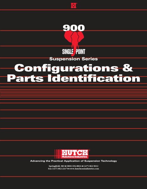
900 Tapered Leaf - Lufkin Industries
900 Tapered Leaf - Lufkin Industries
900 Tapered Leaf - Lufkin Industries
You also want an ePaper? Increase the reach of your titles
YUMPU automatically turns print PDFs into web optimized ePapers that Google loves.
®<br />
<strong>900</strong><br />
SINGLE POINT<br />
Suspension Series<br />
Configurations &<br />
Parts Identification<br />
Hutchens <strong>Industries</strong><br />
Advancing the Practical Application of Suspension Technology<br />
Springfield, MO ■ (800) 654-8824 ■ (417) 862-5012<br />
Fax (417) 862-2317 ■ www.hutchensindustries.com<br />
®
Table of Contents<br />
Pgs. 1-2 Application, Capacity, Standard Features, Options<br />
Pg. 3 How To Order<br />
Pg. 4 Axle Specifications and Mounting Heights Charts<br />
Pg. 5 <strong>900</strong> – 36 thru 60,000 lbs. Bill of Materials,<br />
Spring Identification Chart D<br />
Pgs. 6-7 <strong>900</strong> Illustrated – 3 <strong>Leaf</strong> Shown<br />
Pg. 8 Trunnion Hanger Chart A, Trunnion Tube Chart B,<br />
Trunnion U-Bolt Chart C, Spring End Cap Chart E,<br />
Spring Seat Chart F, Axle U-Bolt Chart G<br />
Pg. 9 Pre-Installation, Axle Installation<br />
1<br />
Pg. 10 Axle Installation (cont.), Preparing Trailer Frame<br />
For Mounting Tandem Assembly<br />
Pg. 11 Preparing Trailer Frame For Mounting Tandem<br />
Assembly (cont.), Installation Using Hutchens<br />
Mounting Brackets<br />
Pg. 12 Mounting Tandem Assembly To Trailer<br />
Pg. 13 Bump-Outs, Axle Alignment, Adjustment<br />
Plate Welding<br />
Pg. 14 Numerical Listing Of Parts, Important: Decal Note<br />
Preface<br />
In the mid-1950’s Hutchens’ engineers realized an urgent need for a heavier, more rugged, single point tandem that would<br />
allow more oscillation without wear and have an adjustable alignment feature. After thorough research and severe road testing,<br />
Hutchens introduced the Hutch 800 model suspension in weight capacities of 36,000, 42,000, 50,000 and 60,000 lbs.<br />
The 800 single point suspension remained virtually unchanged until the very early 1970’s. At that time a split trunnion casting,<br />
which permits easy maintenance and replacement of trunnion bushings should it become necessary, replaced the solid onepiece<br />
casting that had been used previously. This model was known as the 800A.<br />
Still in the early 1970’s Hutchens introduced the 800B. The 800B had inverted trunnion U-bolts that allowed easier maintenance<br />
since the trunnion U-bolt nuts were now on the underside of the suspension. Underslung axle configurations were<br />
added as well.<br />
In the mid-1970’s Hutchens began offering the <strong>900</strong> model single point suspension. The <strong>900</strong> offers many improvements<br />
over earlier single points offered to the market. Greater versatility of axle spacing and spring selection is provided through the<br />
use of a wide selection of springs specifically designed for different load carrying capacities. The <strong>900</strong> offered spring box ends<br />
for square axles as well as round axles.<br />
In the late 1980’s Hutchens introduced a lighter-weight, three-leaf spring, single point suspension in weight capacities of<br />
44,000 and 50,000 lbs. Taking advantage of advances in leaf spring engineering and manufacturing technology, the three-leaf<br />
903 redefined lightweight suspension performance in heavy-duty applications. The addition of this innovative spring to the<br />
rugged <strong>900</strong> series further broadened an already versatile suspension line.<br />
In this booklet we define the <strong>900</strong> Series’Applications, Capacities, Features and Options. We also describe what information<br />
is required to order your <strong>900</strong> Series suspension. Isometric drawings and Bills of Materials are presented for easier identification<br />
of parts. An installation section is included as well. This <strong>900</strong> publication supersedes all previously issued materials relating to<br />
the <strong>900</strong> Series suspension, its installation and its usage. Usage of outdated materials can result in improper installation of the<br />
suspension. The last page of this booklet contains a Numerical Listing Of Parts found within this publication. Parts are listed in<br />
numerical order, and are followed by a parts description and page numbers on which they can be found.<br />
Before beginning any installation procedures, the customer should read all installation instructions thoroughly. Should you<br />
have any questions concerning the <strong>900</strong> Series or any of its predecessors, please contact Hutchens for assistance.<br />
Application<br />
The <strong>900</strong> Series suspensions are designed for heavy-duty and/or off-road applications. The <strong>900</strong> is a single point suspension<br />
connected to the trailer frame by a trunnion located at the center of the suspension. This makes it ideal for logging, heavy load<br />
hauling and dump operations.<br />
Capacity<br />
The <strong>900</strong> Series suspensions are available in Gross Tandem Weight Ratings (G.T.W.R.) of 36,000, 42,000, 44,000, 50,000 and<br />
60,000 lbs.<br />
Features<br />
� Cast steel parts, shot peened and prime painted.<br />
� Extra heavy-duty 5" wide leaf springs.<br />
� Accurate spring alignment preserved by the use of rugged spring guides on the trunnion casting.<br />
� A split trunnion casting permits easy maintenance and replacement of trunnion bushings.<br />
� Axle alignment and realignment made possible by adjustable plates within the spring-end boxes. One adjustment plate on<br />
each axle is welded at the factory. After axle alignment is completed, the installer welds the other adjustment plate to ensure<br />
sustained axle alignment.<br />
� For increased life and flexibility, thick rubber pads are used above the spring leaves in the axle boxes. This construction<br />
permits greater twist freedom in the spring box...a standard flexibility feature that reduces wear and promotes better ride<br />
characteristics.
Options<br />
Standard <strong>900</strong> Series suspensions are available in capacities of 36,000, 42,000, 50,000 and 60,000 lbs. Additionally, lightweight<br />
two-leaf and three-leaf units are available in capacities of 36,000, 44,000 and 50,000 lbs.<br />
Numerous mounting heights (Mtg./ht. = the vertical distance from the center line of the axle to the top of the trunnion<br />
hanger), axle and trunnion combinations are possible. These include overslung (OS, springs over axles) and underslung (US,<br />
springs under axles) axle units as well as overslung (springs over trunnion) and underslung (springs under trunnion) trunnion<br />
configurations.<br />
Mtg./ht.<br />
Overslung Axles – Overslung Trunnion<br />
(Formerly Overslung Axles – Standard Trunnion)<br />
Mtg./ht.<br />
Overslung Axles – Underslung Trunnion<br />
(Formerly Overslung Axles – Optional Trunnion)<br />
Axle Box for Round Axle<br />
2<br />
Mtg./ht.<br />
Underslung Axles – Overslung Trunnion<br />
(Formerly Underslung Axles – Standard Trunnion)<br />
Mtg./ht.<br />
Axle boxes to accommodate 5", 5 3/4" and 6" round axles or 5" x 5" square axles are available.<br />
Underslung Axles – Underslung Trunnion<br />
(Formerly Underslung Axles – Optional Trunnion)<br />
Axle Box for Square Axle<br />
Several different axle centers (AC) are available. See Axle Specifications And Mounting Heights Charts on Page 4.<br />
Trunnion Centers (TC) Spring Centers (SC)<br />
Axle Centers (AC)<br />
Standard spring centers (SC) for the <strong>900</strong> Series suspensions are 38". Other spring centers can be furnished upon request.
Trunnion hanger heights (TH) of 2 1/2", 4 1/2", 6 1/2" and 8 1/2" are available.<br />
Trunnion Height (TH)<br />
Standard trunnion hanger centers (TC) are 22 1/8" (for 38" spring centers). Trunnion centers of 20 1/8" can be specified while<br />
maintaining 38" spring centers.<br />
Trunnion bushings of either rubber or Polyurethane (“free oscillating”) are available. Unless otherwise specified,<br />
trunnion bushings are assumed to be rubber.<br />
When installing your <strong>900</strong> Series suspension, adequate vertical clearance must be provided for the tires, springs and U-bolts.<br />
This is usually accomplished through the use of a mounting bracket or pedestal.<br />
How To Order Your <strong>900</strong> Series Single Point Suspension System<br />
With so many options available on the <strong>900</strong> Series suspensions, each unit must be ordered by a description of the unit desired.<br />
Any abbreviations listed are defined in the Options section of this booklet. Such abbreviations are commonly found in Hutchens<br />
suspension notation.<br />
1. Determine which <strong>900</strong> Series suspension will meet your<br />
weight requirements – 36,000#, 42,000#, 44,000#,<br />
50,000#, or 60,000# GTWR.<br />
2. Select a mounting height (Mtg./ht.) that corresponds to<br />
your particular situation. See Axle Specifications And<br />
Mounting Heights Charts on Page 4.<br />
From this chart please note that mounting height is<br />
dependent upon:<br />
3. Axle configuration – Overslung or Underslung.<br />
4. Axle size – 5", 5 3/4", 6" Round or 5" x 5" Square<br />
(Hutchens does not manufacture or sell axles).<br />
5. Trunnion configuration – Overslung or Underslung.<br />
6. Trunnion Hanger Height (TH) – 2 1/2", 4 1/2", 6 1/2" or<br />
8 1/2". In many instances more than one combination<br />
will result in the same mounting height.<br />
Therefore, all the aforementioned factors should be taken into<br />
consideration when ordering as well as the following:<br />
7. Axle Centers (AC) – See Axle Specifications And<br />
Mounting Heights Charts on Page 4.<br />
8. Spring Centers (SC)<br />
9. Trunnion Centers (TC)<br />
10. To help ease the installation of your <strong>900</strong> Series<br />
suspension you may wish to order a pair of Hutch<br />
mounting brackets (Part #16793-01). See Fig. A below.<br />
Fig. A<br />
24.38"<br />
11.25"<br />
Overall Height<br />
10.00"<br />
Example: A <strong>900</strong> Series suspension with a GTWR of 42,000 lbs., a mounting height of 4" for overslung (OS) 5" round axles, an<br />
overslung (OS) trunnion configuration with a trunnion hanger height (TH) of 2 1/2", axle centers (AC) of 50 1/2",<br />
spring centers (SC) of 38", and trunnion centers (TC) of 22 1/8" would be ordered as follows:<br />
Quantity Suspension Axle Trunnion Axle Trunnion Axle Spring Trunnion<br />
Model Config. Config. Size Height Centers Centers Centers<br />
1 ea. <strong>900</strong>-42 OS (axles) OS (trun.) 5" Rd. 2 1/2 TH 50 1/2 AC 38 SC 22 1/8 TC<br />
Example: A <strong>900</strong> Series suspension with a GTWR of 50,000 lbs., a mounting height of 9 1/2" for underslung (US) 5" x 5"<br />
square axles, an underslung (US) trunnion configuration with a trunnion hanger height (TH) of 6 1/2", axle centers<br />
(AC) of 53", spring centers (SC) of 36", trunnion centers (TC) of 20 1/8" utilizing a three-leaf spring* and free<br />
oscillating trunnion bushings** would be ordered as follows:<br />
Quantity Suspension Axle Trunnion Axle Trunnion Axle Spring Trunnion Spring *<br />
Model Config. Config. Size Height Centers Centers Centers Type<br />
1 ea. <strong>900</strong>-50 US (axles) US (trun.) 5" x 5" Sq. 6 1/2 TH 53 AC 36 SC 20 1/8 TC 3 leaf<br />
w/ free oscillating bushing**<br />
* Three-leaf springs are available for 44,000 and 50,000 lb. units only and must be specified.<br />
** Must be specified.<br />
3
Overslung Axle Specifications And Mounting Heights For Models:<br />
<strong>900</strong>-36 through <strong>900</strong>-44 with 2.5 Trunnion Ht., 5" Rd. & 5" x 5" Sq. Axles<br />
<strong>900</strong>-50 and <strong>900</strong>-60 with 4.5 Trunnion Ht., 5" Rd. & 5" x 5" Sq. Axles<br />
Gross<br />
Tandem Nominal Mounting Height<br />
Weight Number of Axle Spacing Overslung Trunnion Underslung Trunnion<br />
Model Rating Spring Spring Unloaded Loaded Unloaded Loaded Unloaded Loaded<br />
Description (GTWR) Number Leaves<br />
<strong>900</strong>-36 36,000 10054-00 5 48.00 48.75 4.00 3.00 15.00 14.00<br />
<strong>900</strong>-36 36,000 11151-00 5 50.50 51.50 4.00 2.50 15.00 13.50<br />
<strong>900</strong>-36 36,000 16258-01 <strong>Tapered</strong> 2 50.50 51.50 4.00 2.50 13.35 11.85<br />
<strong>900</strong>-42 42,000 9997-00 6 48.00 48.75 4.00 3.00 15.75 14.75<br />
<strong>900</strong>-42 42,000 9998-00 6 50.50 51.50 4.00 2.75 15.75 14.62<br />
<strong>900</strong>-44 44,000 12258-01 <strong>Tapered</strong> 3 50.50 51.50 4.00 2.87 14.50 13.37<br />
<strong>900</strong>-50 50,000 10055-00 7 48.00 48.75 6.00 5.00 18.50 17.12<br />
<strong>900</strong>-50 50,000 9999-00 7 50.50 51.50 6.00 4.62 18.50 17.50<br />
<strong>900</strong>-50 50,000 12258-01 <strong>Tapered</strong> 3 50.50 51.50 6.00 4.62 16.50 15.12<br />
<strong>900</strong>-50 50,000 10000-00 8 54.00 55.25 6.50 5.00 19.75 18.25<br />
<strong>900</strong>-60 60,000 10001-00 9 54.00 55.25 6.50 4.75 20.50 18.75<br />
With 4.5 Trunnion Height Add (<strong>900</strong>-36 thru 44)/(<strong>900</strong>-50 & 60) 2.00/0.00 2.00/0.00 2.00/0.00 2.00/0.00<br />
With 6.5 Trunnion Height Add (<strong>900</strong>-36 thru 44)/(<strong>900</strong>-50 & 60) 4.00/2.00 4.00/2.00 4.00/2.00 4.00/2.00<br />
With 8.5 Trunnion Height Add (<strong>900</strong>-36 thru 44)/(<strong>900</strong>-50 & 60) 6.00/4.00 6.00/4.00 6.00/4.00 6.00/4.00<br />
When 5.75" or 6" Rd. Axles Are Used Add .50 .50 .50 .50<br />
Mounting heights shown for models <strong>900</strong>-50 & 60 are based on a 4.50 high trunnion bracket. Do not use the 2.50 high bracket<br />
on models with 50,000 lbs. GTWR or greater.<br />
Underslung Axle Specifications And Mounting Heights For Models:<br />
<strong>900</strong>-36 through <strong>900</strong>-44 with 2.5 Trunnion Ht., 5" Rd. & 5" x 5" Sq. Axles<br />
<strong>900</strong>-50 and <strong>900</strong>-60 with 4.5 Trunnion Ht., 5" Rd. & 5" x 5" Sq. Axles<br />
Gross<br />
Tandem Nominal Mounting Height<br />
Weight Number of Axle Spacing Overslung Trunnion Underslung Trunnion<br />
Model Rating Spring Spring Unloaded Loaded Unloaded Loaded Unloaded Loaded<br />
Description (GTWR) Number Leaves<br />
<strong>900</strong>-36 36,000 10054-00 5 50.50 50.00 -4.25 -5.25 6.75 5.75<br />
<strong>900</strong>-36 36,000 11151-00 5 53.00 52.25 -4.25 -5.75 6.75 5.25<br />
<strong>900</strong>-36 36,000 16258-01 <strong>Tapered</strong> 2 53.00 52.25 -4.25 -5.75 5.10 3.60<br />
<strong>900</strong>-42 42,000 9997-00 6 50.62 50.00 -5.00 -6.00 6.75 5.75<br />
<strong>900</strong>-42 42,000 9998-00 6 53.00 52.25 -5.00 -6.25 6.75 5.50<br />
<strong>900</strong>-44 44,000 12258-01 <strong>Tapered</strong> 3 53.00 52.25 -5.00 -6.12 5.50 4.37<br />
<strong>900</strong>-50 50,000 10055-00 7 50.62 50.00 -3.00 -4.00 9.50 8.50<br />
<strong>900</strong>-50 50,000 9999-00 7 53.00 52.25 -3.00 -4.37 9.50 8.12<br />
<strong>900</strong>-50 50,000 12258-01 <strong>Tapered</strong> 3 53.00 52.25 -3.00 -4.37 7.50 6.12<br />
<strong>900</strong>-50 50,000 10000-00 8 57.00 56.00 -2.50 -4.00 10.75 9.25<br />
<strong>900</strong>-60 60,000 10001-00 9 57.00 56.00 -2.50 -4.25 11.50 9.75<br />
With 4.5 Trunnion Height Add (<strong>900</strong>-36 thru 44)/(<strong>900</strong>-50 & 60) 2.00/0.00 2.00/0.00 2.00/0.00 2.00/0.00<br />
With 6.5 Trunnion Height Add (<strong>900</strong>-36 thru 44)/(<strong>900</strong>-50 & 60) 4.00/2.00 4.00/2.00 4.00/2.00 4.00/2.00<br />
With 8.5 Trunnion Height Add (<strong>900</strong>-36 thru 44)/(<strong>900</strong>-50 & 60) 6.00/4.00 6.00/4.00 6.00/4.00 6.00/4.00<br />
When 5.75" or 6" Rd. Axles Are Used Subtract -.50 -.50 -.50 -.50<br />
Mounting heights shown for models <strong>900</strong>-50 & 60 are based on a 4.50 high trunnion bracket. Do not use the 2.50 high bracket<br />
on models with 50,000 lbs. GTWR or greater.<br />
4
<strong>900</strong> <strong>Tapered</strong> <strong>Leaf</strong> (shown) and Multi-<strong>Leaf</strong> – 36 thru 60,000<br />
Bill of Materials<br />
Quantity<br />
Overslung Trunnion Underslung Trunnion<br />
Overslung Underslung Overslung Underslung<br />
Item Part No. Axle Axle Axle Axle Description<br />
1 See Chart A, Page 8 2 2 2 2 Trunnion Hanger<br />
2 10376-00 4 4 4 4 Hex Bolt 3/4" – 16 UNF x 4 1/2", GR5<br />
3 895-00 2 2 2 2 Washer, 7GA x 4 1/32 ID x 5 3/4 OD<br />
4 See Chart B, Page 8 1 1 1 1 Trunnion Tube<br />
5 See Chart C, Page 8 4 4 4 4 U-Bolt, Trunnion<br />
6 9640-00 2 2 0 0 Top Plate – Cast, Square U-Bolt<br />
7 See Chart D, Below 2 2 2 2 Spring<br />
8 See Chart E, Page 8 4 4 4 4 Spring End Cap<br />
9 841-00 20 4 20 4 Hex Nut, Self Locking, 3/4" – 16 UNF<br />
10 9293-00 16 8 16 8 Hex Bolt, 5/8" – 18 UNF x 2", GR5<br />
11 817-00 32 0 32 0 Washer, 1/8" x 13/16 ID x 1 1/2 OD<br />
12 814-00 8 8 8 8 Rubber Pad – Plain<br />
13 10608-00 4 4 4 4 Adjustment Plate<br />
14 See Chart F, Page 8 4 4 4 4 Spring Seat<br />
15 10273-00 16 8 16 8 Washer, 1/8" x 21/32 ID x 1 15/16 OD<br />
16 11513-03 16 8 16 8 Hex Locknut, 5/8" – 18 UNF<br />
17 See Chart G, Page 8 8 8 8 8 U-Bolt – Axle<br />
18 12919-01 ‡ 2 2 2 2 Galvanized Liner – .040 x 4.75 x 10.00<br />
19 891-00 2 2 2 2 Trunnion Hub – Upper Half<br />
20 890-00 2 2 2 2 Rubber Bushing – Trunnion Hub<br />
23276-01 2 2 2 2 Free Oscillating Trunnion Bushing*<br />
21 898-00 2 2 — — Trunnion Hub – Lower Half<br />
892-00 — — 2 2 Trunnion Hub – Lower Half<br />
22 837-00 8 8 8 8 Washer, 1/8" x 1 1/4 ID x 2 1/4 OD<br />
23 836-00 8 8 8 8 Hex Nut, 1 1/8" – 12 UNF x 1 1/2 HI<br />
24 10562-00 0 16 0 16 Flange Locknut – 1-14 UNS, GRF<br />
25 820-00 0 0 2 2 Spring Clamp Plate<br />
26 10488-00 4 4 4 4 Pressure Plate, 5" x 5" Axle Only<br />
Chart D – Spring Identification ** (Item #7)<br />
Unit Weight<br />
Capacity (lbs.)<br />
36,000 36,000 36,000 42,000 42,000 44/50,000 50,000 50,000 50,000 60,000<br />
Number of<br />
Leaves<br />
<strong>Tapered</strong> 2 ‡ 5 5 6 6 <strong>Tapered</strong> 3 ‡ 7 7 8 9<br />
Spring<br />
Part No.<br />
16258-01 10054-00 11151-00 9997-00 9998-00 12258-01 10055-00 9999-00 10000-00 10001-00<br />
* Available upon request, must be specified.<br />
** For a detailed description of axle spacings, mounting heights, etc. obtained when utilizing the above springs, see the Axle<br />
Specifications And Mounting Heights Charts on Page 4.<br />
‡ A galvanized liner is required on the tension surface (bottom side) of the spring when taper leaf (2 and 3 leaf) springs are<br />
utilized. Liners are not required on flat plate (5, 6, 7, 8 and 9 leaf) springs.<br />
5
Overslung Trunnion — Overslung Axle<br />
9<br />
1<br />
2<br />
3<br />
4<br />
21<br />
22<br />
23<br />
5<br />
6<br />
7<br />
6<br />
Pressure Plate (Item #26)<br />
Required<br />
8<br />
18<br />
19<br />
20<br />
14<br />
5" x 5" Axle Only<br />
<strong>900</strong><br />
17<br />
26<br />
8<br />
9<br />
10<br />
11<br />
12<br />
13<br />
14<br />
15<br />
16<br />
17
Underslung Trunnion — Underslung Axle<br />
9<br />
1<br />
2<br />
3<br />
4<br />
7<br />
17<br />
Pressure Plate (Item #26)<br />
Required<br />
26<br />
5<br />
21<br />
20<br />
19<br />
7<br />
18<br />
25<br />
22<br />
23<br />
5" x 5" Axle Only<br />
14<br />
8<br />
17<br />
14<br />
16<br />
15<br />
12<br />
13<br />
8<br />
10<br />
24
<strong>900</strong> — 36, 42, 44, 50 and 60,000<br />
Chart A – Trunnion Hanger (Item #1)<br />
Trunnion Hanger Height<br />
2 1/2" 4 1/2" 6 1/2" 8 1/2"<br />
Part No. 850-01 10476-03 849-01 897-01<br />
Chart B – Trunnion Tube (Item #4)<br />
Spring Centers/Trunnion Hanger Centers<br />
Unit Weight Capacity (lbs.) 38"/22.12" 36"/20.12" 44"/28.12" 42"/26.12" 41"/25.12"<br />
36,000 - 44,000 893-01 893-04 893-07 893-09 893-11<br />
50,000 and 60,000 893-02 893-05 893-08 893-10 893-12<br />
Chart C – Trunnion U-Bolt (Item #5)<br />
Unit Weight/Spring<br />
Trunnion Configuration<br />
Capacity (lbs.)/Part No. Overslung Lgth. Underslung Lgth.<br />
36,000/10054-00 9639-01 12 5/16" 835-02 13 3/4"<br />
36,000/11151-00 9639-01 12 5/16" 835-02 13 3/4"<br />
36,000/16258-01 9639-10 11" 835-01 12 3/8"<br />
42,000/9997-00 9639-02 13 1/8" 835-03 14 5/8"<br />
42,000/9998-00 9639-02 13 1/8" 835-03 14 5/8"<br />
44,000/12258-01 9639-01 12 5/16" 835-02 13 3/4"<br />
50,000/10055-00 9639-03 13 15/16" 835-04 15 3/8"<br />
50,000/9999-00 9639-03 13 15/16" 835-04 15 3/8"<br />
50,000/12258-01 9639-01 12 5/16" 835-02 13 3/4"<br />
50,000/10000-00 9639-04 14 11/16" 835-06 16 1/8"<br />
60,000/10001-00 9639-05 15 1/2" 835-05 17"<br />
Chart E – Spring End Cap (Item #8)<br />
Unit Weight<br />
Axle Configuration<br />
Axle Size Capacity (lbs.) Overslung Underslung<br />
5" Rd. – 5" x 5" Sq. 36,000 10049-00 10050-02<br />
42-60,000 9937-00 9941-02<br />
5 3/4" Rd. – 6" Rd. 36,000 10049-00 —<br />
42-60,000 9937-00 9942-02<br />
Chart F – Spring Seat (Item #14)<br />
Axle Configuration<br />
Axle Size Overslung Underslung<br />
5" Rd. 9934-02 9938-00<br />
5" x 5" Sq. 9935-02 9939-00<br />
5 3/4" Rd. 9936-03 9940-00<br />
6" Rd. 9936-04 9940-01<br />
Chart G – Axle U-Bolt (Item #17)<br />
Unit Weight<br />
Axle Configuration<br />
Axle Size Capacity (lbs.) Overslung Lgth. Underslung Lgth.<br />
5" Rd. 36,000 10060-01 7" 10064-01 9 3/4"<br />
42-60,000 10060-01 7" 10064-02 10 1/2"<br />
5" x 5" Sq. 36,000 10063-02 7 7/8" 10067-02 10 1/2"<br />
42-60,000 10063-02 7 7/8" 10067-03 11 1/8"<br />
5 3/4" Rd. 36,000 10061-01 8" 10065-01 11 1/2"<br />
42-60,000 10061-01 8" 10065-01 11 1/2"<br />
6" Rd. 36,000 10062-01 8" 10066-01 11 1/2"<br />
42-60,000 10062-01 8" 10066-01 11 1/2"<br />
8
Installation<br />
Pre-Installation<br />
The <strong>900</strong> single point suspension is shipped assembled - except for the axle U-bolts, nuts and washers which are packaged separately.<br />
On each axle there is one adjustment plate factory welded, and one that is welded by the installer following axle alignment.<br />
Refer to the preceding pages for detailed component information, unit capacity, and mounting heights. Before beginning<br />
any installation procedures, the customer should read all installation instructions thoroughly.<br />
Prior to installation check for interference between brake camshafts and suspension components. Recommended camshaft locations<br />
are as follows:<br />
Fig. 1<br />
Overslung Axle Configuration<br />
Locate brake camshafts at the<br />
axles horiz. centerline or below<br />
King pin<br />
center point<br />
Brake Camshafts<br />
Horiz.<br />
Lc<br />
Springs must be<br />
parallel to each other<br />
and perpendicular to<br />
the trunnion tube.<br />
9<br />
Underslung Axle Configuration<br />
Locate brake camshafts at the<br />
axles horiz. centerline or above<br />
Inspect the suspension assembly to be certain that spring alignment has not been destroyed during shipment.<br />
Set the suspension on the axles. Check to see that the springs are parallel to each other and perpendicular to the trunnion tube.<br />
See Fig. 2. Be sure the nuts on the trunnion hub U-bolts are torqued to specification.<br />
Fig. 2<br />
Axle Installation<br />
1. With the axle camber up, locate the center of both axles<br />
by measuring between the brake flanges and marking the<br />
center.<br />
2. Place the suspension on the axles, making certain that the<br />
axle seats are an equal distance from the center of the<br />
axle. All axle seats should measure the same distance from<br />
the brake flanges.<br />
3. Align the camber marks on the top of the axle with the<br />
centerline of the axle seats. Be certain that all axle seats fit<br />
90°<br />
90°<br />
Trunnion Tube<br />
Spring<br />
90°<br />
90°<br />
Spring<br />
<strong>900</strong><br />
the axle properly. If necessary, grind the axle seats to<br />
ensure that they fit properly, and are horizontal and parallel.<br />
4. Tack-weld seats in place and recheck to make certain they<br />
are still level, parallel, and in the proper location and alignment.<br />
Important: On underslung models, axle seats must be located<br />
beneath axles. See Fig. 3. Be certain that the camber<br />
marks are on top of the axle.
Fig. 3<br />
Axle Seat<br />
Axle<br />
Overslung Axle<br />
Axle<br />
Axle Seat<br />
Underslung Axle Underslung Axle<br />
5. Check tire clearance with the suspension at this time.<br />
See Fig. 4.<br />
6. Following the axle manufacturer’s welding recommendations,<br />
weld the axle seats to the axle using 3/8" fillet<br />
welds on front and rear of the axle seats. See Fig. 3.<br />
Fig. 4<br />
Suspension Lc<br />
48"<br />
Inside Tire<br />
Standard<br />
Trunnion<br />
Centers<br />
22 1/8"<br />
2 3/4"<br />
5"<br />
5"<br />
Overslung Axle<br />
3/8" 3/8"<br />
Trunnion<br />
Tube<br />
9 5/8"<br />
Trunnion<br />
Hanger<br />
6.25"<br />
7"<br />
9.75"<br />
4 13/16"<br />
1 15/32"<br />
21/32" x 1"<br />
Axle Seat<br />
2 15/16"<br />
Axle<br />
Axle<br />
Axle Seat<br />
1" Min Tire Clearance Required<br />
Necessary For Proper Tire Clearance.<br />
Preparing Trailer Frame For Mounting Tandem Assembly<br />
Determine suspension location on the trailer frame by<br />
measuring from the king pin to outside of the frame at<br />
desired location and marking each side at the suspension’s<br />
centerline.The frame should now be prepared for mounting<br />
of the suspension in one of the following three ways:<br />
1. Use of the optional Hutch mounting brackets (Part<br />
#16793-01). Two each are required. See Fig. A on<br />
Page 3.<br />
10<br />
Caution: Do not attach welding ground clamps to U-bolts,<br />
springs or axles except to designated weld points. These<br />
parts should be protected from weld splatter.<br />
7. Assemble axle U-bolts to spring end boxes, but do<br />
not tighten.<br />
4 1/2"<br />
9"<br />
Standard<br />
Springs<br />
Centers<br />
38"<br />
Note: Additional bracing (furnished by the installer)<br />
connecting one mounting bracket with the other is recommended.<br />
See Fig. 5 on Page 11.<br />
2. Fabrication of your own mounting bracket.<br />
3. Bolting directly to the frame.
Note: When any of the aforementioned methods of mounting the suspension are utilized a “minimum dimension”<br />
must be maintained between the trunnion tube centerline and the top of the suspension components. See Fig. 5.<br />
This minimum dimension is tabulated in Chart H.<br />
Chart H<br />
Minimum Dimension<br />
Number of Overslung Underslung<br />
Model Spring Leaves Trunnion Trunnion<br />
<strong>900</strong>-36 2 9" 4 1/2"<br />
<strong>900</strong>-36 5 10 1/2" 4 1/2"<br />
<strong>900</strong>-42 6 11 1/4" 4 1/2"<br />
<strong>900</strong>-44 3 10" 4 1/2"<br />
Note:<br />
1. a) The upper trailer structure shown is intended to<br />
be a generic representation of a typical installation,<br />
and is not intended to be a detailed recommendation<br />
for a fabrication of a trailer subframe.<br />
b) The welds attaching the mounting bracket to the<br />
subframe will be determined by the configuration of<br />
the structure, and are the responsibility of the trailer<br />
manufacturer.<br />
c) As a general recommendation, the frame bracket<br />
should be welded to the trailer structure with either<br />
a solid weld or skip welds that cover at least 60% of<br />
the mounting bracket perimeter. Do not weld within<br />
1/2" of any raw edges of the trailer main rails or<br />
crossmembers. Welding should be in accordance<br />
with AWS E70XX procedures or equivalent.<br />
2. Mounting bracket bolts are to be furnished by<br />
installer – size 5/8" fastener, Grade 5 or better.<br />
11<br />
Minimum Dimension<br />
Number of Overslung Underslung<br />
Model Spring Leaves Trunnion Trunnion<br />
<strong>900</strong>-50 3 10" 4 1/2"<br />
<strong>900</strong>-50 7 12" 4 1/2"<br />
<strong>900</strong>-50 8 12 3/4" 4 1/2"<br />
<strong>900</strong>-60 9 13 1/2" 4 1/2"<br />
Installation Using Hutchens Mounting Brackets (Part #16793-01)<br />
Fig. 5<br />
10.00"<br />
Channel Brace – 2 req’d<br />
Furnished by installer<br />
Minimum recommended size:<br />
.25 x 1.5 x 7 fabricated channel,<br />
A36 C7 x 9.8# structural channel,<br />
or similar.<br />
Side View (Typ)<br />
See Note 1 for mounting<br />
bracket welds<br />
▲2<br />
.31"<br />
1.00"<br />
Min.Trunnion Ht.<br />
– See Chart J –<br />
Chart J<br />
Number of<br />
Spring Leaves<br />
2 3 5 6 7 8 9<br />
Min Trunnion<br />
Hanger Ht.<br />
2.50 4.50 4.50 4.50 6.50 6.50 6.50<br />
2 Welds<br />
4 Pls<br />
2 Welds<br />
4 Pls<br />
Channel Frame End View<br />
40.00"<br />
Frame Width Shown<br />
Trunnion mounting bracket should bear on side rail<br />
and crossmembers – install shim plate if necessary.<br />
.25"<br />
.50"<br />
No<br />
Weld<br />
Typ<br />
Minimum<br />
Dimension<br />
(Chart H)<br />
22.13"<br />
1.50"<br />
Trunnion Hgr<br />
38.00"<br />
I Beam Frame End View<br />
38.00"<br />
Beam Center Shown<br />
Trunnion mounting bracket should bear on side rail<br />
and crossmembers – install shim plates if necessary.<br />
.25"<br />
.50"<br />
No<br />
Weld<br />
Typ<br />
22.13"<br />
1.50"<br />
Trunnion Hgr<br />
38.00"<br />
Spring<br />
.25"<br />
Spring<br />
.25"<br />
Minimum<br />
Dimension<br />
(Chart H)<br />
3 Welds<br />
4 Pls<br />
3 Welds<br />
4 Pls
Mounting Tandem Assembly To Trailer<br />
1. Attach trunnion hanger to mounting bracket or<br />
trailer frame. Do not tighten bolts.<br />
Fig. 6<br />
King pin<br />
center point<br />
3. After alignment, tighten the 5/8" trunnion hanger<br />
fasteners to specification and recheck trunnion<br />
alignment.<br />
4. When the trunnion tube has been aligned and the<br />
trunnion hanger bolts have been torqued, weld the<br />
Fig. 7 Fig. 8<br />
Weld trunnion<br />
brackets all around<br />
to trailer bracket.<br />
5/16"<br />
Note: To achieve non-standard trunnion hanger heights,<br />
a spacer is sometimes used atop the trunnion hanger.<br />
See Fig. 8. When using a spacer, it must be solidly<br />
welded to both the trunnion hanger and mounting<br />
bracket or frame. Do not stack spacers.<br />
Fig. 9<br />
Spring<br />
Trunnion<br />
Tube<br />
Trunnion<br />
Tube<br />
U-Bolt<br />
T 1<br />
T 2<br />
Trunnion Hub<br />
12<br />
2. Align the trunnion tube with the king pin.<br />
Dimensions T 1 and T 2 must be equal. See Fig. 6.<br />
trunnion hanger all around to the mounting bracket<br />
or trailer frame and frame member. See Fig. 7.<br />
When using the 852-00 or 12970-01 spacer,<br />
insert spacer between hanger casting and<br />
extension bracket and weld solidly top and<br />
bottom. Do not stack spacers.<br />
11"<br />
5 1/2"<br />
After attaching top of bracket to<br />
frame tighten to specification.<br />
5 1/2"<br />
1" Part No. 12970-01<br />
or 2" Part No. 852-00<br />
5. After the trunnion hangers have been attached to the<br />
trailer frame, tighten the 3/4" clamp fasteners to<br />
specification. See Fig. 9.
Bump-Outs<br />
When rubber bushings are utilized in the trunnion connection,<br />
the maximum oscillation at the trunnion hub should not<br />
exceed 15° above or below horizontal. See Fig. 10. Spring<br />
Fig. 10<br />
Axle Alignment<br />
After the suspension has been installed under the trailer, the<br />
axles should be properly aligned in relation to the trailer king<br />
pin in the following manner: Measure the distance from the<br />
king pin to the centerline of the spindles on the front axle. As<br />
noted in Fig. 11, dimensions A and B must be equal within 1/8<br />
of an inch. After aligning the front axle, tighten the U-bolts and<br />
end clamp bolts to specification on that axle only. Next, align<br />
Fig. 11<br />
Check dimension E, the lateral centerline relationship of the<br />
trailer body and axles. Dimension E must not exceed 1/4 of<br />
an inch. At this time, recheck the alignment of the front axle<br />
with the king pin, and the rear axle with the front axle. After<br />
Adjustment Plate Welding<br />
end boxes are designed to accept bump-outs or stops, which<br />
the installer should provide to assure tire clearance or to limit<br />
oscillation – whichever becomes critical first.<br />
On each axle there is one adjustment plate that is welded at the factory and one that is not.<br />
After alignment has been completed, weld the unwelded alignment plate exactly like the one that has been welded<br />
at the factory. See Fig. 12.<br />
Fig. 12<br />
King pin<br />
center point<br />
Horiz.<br />
15° max<br />
15° max<br />
A = B ± 1/8<br />
C = D ± 1/16<br />
E ≤ 1/4<br />
A<br />
B<br />
15° max<br />
15° max<br />
the rear axle with the front axle. As noted in Fig. 11, dimensions<br />
C and D must be equal within 1/16 of an inch. After<br />
aligning the rear axle with the front axle, tighten the U-bolts<br />
and end clamp bolts on the rear axle. Refer to TTMA RP No.<br />
71-90 (Trailer Axle Alignment) for more detail.<br />
alignment has been accomplished, tighten the U-bolts and<br />
nuts to specification.<br />
CAUTION – These adjustment plates MUST BE WELDED BEFORE operating the trailer.<br />
Check all fasteners (U-bolts, end cap, trunnion hub, etc.) to make sure they are torqued to specification. Torque for all fasteners<br />
should be checked after an initial break-in period, and periodically thereafter. See Decal Note on Page 14.<br />
13<br />
C<br />
D<br />
Horiz.<br />
1/4"<br />
4"<br />
E
Numerical Listing of Parts<br />
Part No. Description Pg. #<br />
814-00 Rubber Pad – Plain 5<br />
817-00 Washer - 1/8 x 13/16 ID x 1 1/2 OD 5<br />
820-00 Spring Clamp Plate 5<br />
835-01 U-Bolt – 1.067 DIA, 5 7/8 RD x 12 3/8 8<br />
835-02 U-Bolt – 1.067 DIA, 5 7/8 RD x 13 3/4 8<br />
835-03 U-Bolt – 1.067 DIA, 5 7/8 RD x 14 5/8 8<br />
835-04 U-Bolt – 1.067 DIA, 5 7/8 RD x 15 3/8 8<br />
835-05 U-Bolt – 1.067 DIA, 5 7/8 RD x 17 8<br />
835-06 U-Bolt – 1.067 DIA, 5 7/8 RD 16 1/8 8<br />
836-00 Hex Nut – 1 1/8 - 12 UNF, 1 1/2 HI 5<br />
837-00 Washer – 1/8 x 1 1/4 ID x 2 1/4 OD 5<br />
841-00 Hex Nut – Self Locking, 3/4 - 16 UNF 5<br />
849-01 Trunnion Hgr. – Cast, 6 1/2 HI, 11 LG 8<br />
850-01 Trunnion Hgr. – Cast, 2 1/2 HI, 11 LG 8<br />
852-00 Spacer – Trunn Hgr, 2 High, 11 LG 12<br />
890-00 Rubber Bushing – Trunnion Hub 5<br />
891-00 Trunnion Hub – Upper Half, Cast 5<br />
892-00 Trunnion Hub – Lower Half, Cast 5<br />
893-01 Trunnion Tube – 1/2 Wall, 48 LG 8<br />
893-02 Trunnion Tube – 3/4 Wall, 48 LG 8<br />
893-04 Trunnion Tube – 1/2 Wall, 46 LG 8<br />
893-05 Trunnion Tube – 3/4 Wall, 46 LG 8<br />
893-07 Trunnion Tube – 1/2 Wall, 54 LG 8<br />
893-08 Trunnion Tube – 3/4 Wall, 54 LG 8<br />
893-09 Trunnion Tube – 1/2 Wall, 52 LG 8<br />
893-10 Trunnion Tube – 3/4 Wall, 52 LG 8<br />
893-11 Trunnion Tube – 1/2 Wall, 51 LG 8<br />
893-12 Trunnion Tube – 3/4 Wall, 51 LG 8<br />
895-00 Washer – 7 GA x 4 1/32 ID x 5 3/4 OD 5<br />
897-01 Trunnion Hgr. - Cast 8 1/2 HI, 11 LG 8<br />
898-00 Trunnion Hub – Lower Half, Cast 5<br />
9293-00 Hex Bolt – 5/8 – 18 UNF x 2, GR 5 5<br />
9639-01 U-Bolt – 1.067 DIA, 5 1/8 SQ, 12 5/16 8<br />
9639-02 U-Bolt – 1.067 DIA, 5 1/8 SQ, 13 1/8 8<br />
9639-03 U-Bolt – 1.067 DIA, 5 1/8 SQ, 13 15/16 8<br />
9639-04 U-Bolt – 1.067 DIA, 5 1/8 SQ, 14 11/16 8<br />
9639-05 U-Bolt – 1.067 DIA, 5 1/8 SQ, 15 1/2 8<br />
9639-10 U-Bolt – 1.067 DIA, 5 1/8 SQ, 11 8<br />
9640-00 Top Plate – Cast, SQ U-Bolt 5<br />
9934-02 Spring Seat – Adj., 5 RD, OS 8<br />
9935-02 Spring Seat – Adj., 5 SQ, OS 8<br />
9936-03 Spring Seat – Adj., 5 3/4 RD, OS 8<br />
Important: Warning Decal Note<br />
14<br />
Part No. Description Pg. #<br />
9936-04 Spring Seat – Adj., 6 RD, OS 8<br />
9937-00 Spring End Cap – OS 8<br />
9938-00 Spring Seat – 5 RD, US 8<br />
9939-00 Spring Seat – 5 SQ, US 8<br />
9940-00 Spring Seat – 5 3/4 RD, US 8<br />
9940-01 Spring Seat – 6 RD, US 8<br />
9941-02 Spring End Cap – Adj., 5 RD & 5 SQ, US 8<br />
9942-02 Spring End Cap – Adj., 5 3/4 RD & 6 RD, US 8<br />
9997-00 Spring Assembly – 6 <strong>Leaf</strong>, 42,000 LB, 48 AC 4, 5, 8<br />
9998-00 Spring Assembly – 6 <strong>Leaf</strong>, 42,000 LB, 50.5 AC 4, 5, 8<br />
9999-00 Spring Assembly – 7 <strong>Leaf</strong>, 50,000 LB, 50.5 AC 4, 5, 8<br />
10000-00 Spring Assembly – 8 <strong>Leaf</strong>, 50,000 LB, 54 AC 4, 5, 8<br />
10001-00 Spring Assembly – 9 <strong>Leaf</strong>, 60,000 LB, 54 AC 4, 5, 8<br />
10049-00 Spring End Cap – OS, 36,000 LB 8<br />
10050-02 Spring End Cap – Adj., US, 36,000 LB 8<br />
10054-00 Spring Assembly – 5 <strong>Leaf</strong>, 36,000 LB, 48 AC 4, 5, 8<br />
10055-00 Spring Assembly – 7 <strong>Leaf</strong>, 50,000 LB, US 4, 5, 8<br />
10060-01 U-Bolt – 0.706 DIA, 5 RD x 7 8<br />
10061-01 U-Bolt – 0.706 DIA, 5 3/4 RD x 8 8<br />
10062-01 U-Bolt – 0.706 DIA, 6 RD x 8 8<br />
10063-02 U-Bolt – 0.706 DIA, 5 SQ x 7 7/8 8<br />
10064-01 U-Bolt – 0.949 DIA, 5 RD x 9 3/4 8<br />
10064-02 U-Bolt – 0.949 DIA, 5 RD x 10 1/2 8<br />
10065-01 U-Bolt – 0.949 DIA, 5 3/4 RD x 11 1/2 8<br />
10066-01 U-Bolt – 0.949 DIA, 6 RD x 11 1/2 8<br />
10067-02 U-Bolt – 0.949 DIA, 5 SQ x 10 1/2 8<br />
10067-03 U-Bolt – 0.949 DIA, 5 SQ x 11 1/8 8<br />
10273-00 Washer – 1/8 x 21/32 ID x 1 5/16 OD 5<br />
10376-00 Hex Bolt – 3/4 – 16 UNF x 4 1/2 LG, GR 5 5<br />
10476-03 Trunnion Hgr. – Cast, 4 1/2 HI 8<br />
10488-00 Pressure Plate – Cast, 5 SQ 5<br />
10562-00 Flange Locknut – 1-14 UNS, GRF, Phos & Oil 5<br />
10608-00 Plate – Adj. 5<br />
11151-00 Spring Assembly – 5 <strong>Leaf</strong>, 36,000 LB, 50.5 AC 4, 5, 8<br />
11513-03 Hex Locknut – 5/8 – 18 UNF, 28, GRC 5<br />
12258-01 Spring Assembly – 3 <strong>Leaf</strong> 4, 5, 8<br />
12919-01 Galvanized Liner – .040 x 4.75 x 10.00 5<br />
12970-01 Spacer – Trunn Hgr, 1 High, 11 LG 12<br />
16087-01 Decal – <strong>900</strong> Series 14<br />
16258-01 Spring Assembly – 2 <strong>Leaf</strong> 4, 5, 8<br />
16793-01 Mounting Bracket – H<strong>900</strong>, 10.00 HI 3, 11<br />
23276-01 Trunnion Bushing – Free Oscillating, 5<br />
5% Oil Filled PUR, 9.00 LG<br />
When the installation of your “Hutch” single point suspension is complete and the trailer has been painted, a torque requirement<br />
decal (Part No. 16087-01 Rev. E) should be installed in plain view, preferably on the driver’s side of the trailer immediately above the<br />
suspension. It is essential that the correct decal is in plain view on each trailer. Decals are shipped with the suspension. If decals are<br />
not received, or if for any reason additional decals are wanted, contact our Customer Service Department at (800) 654-8824 or fax<br />
(417) 862-2317 and decals will be shipped promptly at no charge.<br />
!<br />
WARNING<br />
SAFETY ALERT! (1) FOLLOW ALL TORQUE REQUIREMENTS. (2) DO NOT USE ANY COMPONENT WITH VISIBLY WORN<br />
OR DAMAGED THREADS. FAILURE TO FOLLOW THESE SAFETY ALERTS CAN LEAD TO LOSS OF VEHICLE CONTROL,<br />
PROPERTY DAMAGE, SERIOUS PERSONAL INJURY OR DEATH.<br />
Hutchens Suspension Torque Requirements – <strong>900</strong>/440 Series (Decal Part Number 16087-01 Rev. E)<br />
After an initial break in period, approximately 1000 miles, and at least every 4 months periodically thereafter, ALL bolts and nuts<br />
should be checked to insure that recommended torque values are being maintained.<br />
Oil torque values listed are for new fasteners with lubricated threads. It is recommended that new installations be performed with oiled<br />
fasteners. For dry threads which have been in service, use the higher torque values which are noted below.<br />
OILED DRY<br />
1 1/8-12 UNF 670 lb-ft 880 lb-ft<br />
1-14 UNF 540 lb-ft 730 lb-ft<br />
7/8-14 UNF 500 lb-ft 670 lb-ft<br />
3/4-16 UNF 220 lb-ft 300 lb-ft<br />
5/8-18 UNF 130 lb-ft 180 lb-ft<br />
Hutchens <strong>Industries</strong>, Inc., P.O. Box 1427, Springfield, Missouri 65801-1427 Toll Free 1 (800) 654-8824
Hutchens <strong>Industries</strong><br />
Advancing the Practical Application of Suspension Technology<br />
Springfield, MO ■ (800) 654-8824 ■ (417) 862-5012<br />
Fax (417) 862-2317 ■ www.hutchensindustries.com<br />
®<br />
September 2004–CA


