MOBILE COMPUTER CART - Rubbermaid Medical Solutions
MOBILE COMPUTER CART - Rubbermaid Medical Solutions
MOBILE COMPUTER CART - Rubbermaid Medical Solutions

Create successful ePaper yourself
Turn your PDF publications into a flip-book with our unique Google optimized e-Paper software.
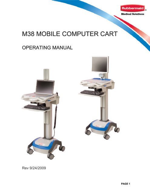
M38 <strong>MOBILE</strong> <strong>COMPUTER</strong> <strong>CART</strong><br />
OPERATING MANUAL<br />
Rev 9/24/2009<br />
PAGE 1
TABLE OF CONTENTS<br />
SUMMARY OF WARNINGS .................................................................................. 3<br />
START-UP.............................................................................................................. 5<br />
GENERAL OPERATION ........................................................................................ 9<br />
LOCKING DRAWER (Models 9M38-01-XXX) ..................................................... 10<br />
POWER SYSTEM OVERVIEW (AC Powered Carts Only)................................. 10<br />
BATTERY REMOVAL AND REPLACEMENT ..................................................... 13<br />
POWER SYSTEM REMOVAL/INSTALLATION................................................... 15<br />
MAINTENANCE ................................................................................................... 16<br />
CLEANING ........................................................................................................... 16<br />
TROUBLESHOOTING ......................................................................................... 17<br />
WARRANTY & SERVICE OVERVIEW ................................................................ 18<br />
REPLACEMENT PARTS AND REQUESTING SERVICE ................................... 18<br />
PAGE 2
SUMMARY OF WARNINGS<br />
The power system is designed for power cart mounted equipment only. Do not connect equipment that is not<br />
mounted on the cart into the power system outlets. Do not connect cart mounted equipment directly into a<br />
power<br />
source that is not mounted to the cart.<br />
Where the integrity of the external PROTECTIVE EARTH CONDUCTOR arrangement is in doubt, the<br />
equipment<br />
shall be operated from its internal electrical power source (battery).<br />
The supplied spiral cord is rated for medical use. Connecting the cord to an outlet that is not medical grade<br />
(indicated with a green dot) will not ensure grounding protection.<br />
Spiral<br />
cord, power system and cart are for INDOOR use only. DO NOT OPERATE OUTDOORS.<br />
Keep spiral cord away from water. DO NOT PLUG CORD INTO OUTLET IF WET.<br />
DO NOT OPERATE POWER SYSTEM IF WET. If your cart becomes wet, unplug it immediately, wipe off any<br />
excess<br />
liquid, and allow it to dry before using again.<br />
Breaking<br />
the seal on the battery to add water will damage the battery and could cause injury.<br />
EQUIPMENT not suitable for use in the presence of a FLAMMABLE ANESTHETIC FIXTURE WITH AIR, or<br />
W ITH METERED OXYGEN OR NITROUS OXIDE.<br />
I nspect spiral cord before each use. DO NOT USE CORD IF DAMAGED.<br />
Fully insert spiral cord plug into outlet. DO NOT unplug by pulling on cord. DO NOT remove, bend or modify<br />
any<br />
metal prongs or pins of spiral cart cord.<br />
DO<br />
NOT use excessive force to make connections.<br />
DO<br />
NOT ALLOW CORD TO OVERHEAT<br />
DO NOT drive, drag or place objects over spiral cord. Do not stand or walk on spiral cord.<br />
Only authorized personnel, experienced in servicing electrical equipment should open the power system.<br />
Do not use an electrical extension cord with your cart.<br />
Do not use a flammable cleaner on the station as it can result in fire or explosion.<br />
Do not adjust lift mechanism until cart has been outfitted with technology. Failure to do so may<br />
cause shuttle and work surface to rise rapidly when actuator is released potentially causing personal<br />
injury or damage to the cart.<br />
Symbol Signal Word Level of Hazard<br />
Indicates a situation that does not present any<br />
IMPORTANT hazard but is very important in maintaining a<br />
well functioning cart.<br />
Consult accompanying document to avoid a<br />
ATTENTION potentially hazardous situation which may<br />
result in minor or moderate injury.<br />
Indicates an impending electrical hazard which,<br />
ELECTRICAL if not avoided, may result in personal injury, fire<br />
and/or death.<br />
LEAD BATTERY<br />
MUST BE<br />
RECYCLED<br />
<strong>CART</strong> DISPOSAL<br />
Dispose of this cart according to<br />
local guidelines and regulations<br />
for waste. Contact <strong>Rubbermaid</strong><br />
Customer Service for more<br />
information: 1-888-859-8294<br />
Transport/Storage<br />
Care should be taken to transport<br />
and store this system within a<br />
temperature range of 32º F to 90º F<br />
(0º C to 32º C); Pressure 500 hPa<br />
to 1060 hPa; Humidity 20% RH to<br />
95% RH non-condensing<br />
PAGE 3
INTRODUCTION<br />
<strong>Rubbermaid</strong> computer carts combine a compact, lightweight design, superior ergonomics and a<br />
comprehensive set of nursing features making them ideal for point of care applications. This<br />
manual covers the following three configurations:<br />
8<br />
1. AC Powered Computer Carts operate an LCD monitor with a small form factor CPU that<br />
can be housed under the work surface.<br />
2. AC Powered Computer Carts with External CPU Storage operate an LCD monitor with<br />
small form factor CPU too large to be stored internally.<br />
3. Non-Powered Computer Carts operate self powered devices such as notebooks and tablet<br />
PC’s.<br />
17<br />
18<br />
20<br />
15<br />
STANDARD FEATURES ACROSS<br />
1. Shuttle<br />
2. Lift Mechanism Tension Adjustment<br />
3. Lift Mechanism Tension Indicator<br />
4. Work Surface with Document Protector<br />
5. Ergonomic Front Handle<br />
6. Keyboard Light<br />
7. Height Adjustment Lever<br />
8. Adjustable Keyboard Tray with L/R<br />
Mouse Surface<br />
SKU SPECIFIC<br />
1<br />
7<br />
10<br />
POWERED <strong>CART</strong> FEATURES<br />
17. LCD Monitor Bracket<br />
18. Power System Interface<br />
19. Battery Access Panel<br />
20. Power System Access Panel<br />
22. Secondary Outlet Strip (not shown)<br />
2<br />
23<br />
9<br />
3<br />
11<br />
19<br />
24<br />
5<br />
6<br />
4<br />
13<br />
14<br />
25<br />
12<br />
27<br />
9. Mast and T-Track Mounting Channel<br />
10. General Purpose Bins<br />
11. Contoured Rear Handle<br />
12. Internal Technology Cabinet<br />
13. Key Access to technology cabinet<br />
14. AC Outlet Strip<br />
15. Spiral Power Cord<br />
16. Keyless locking drawer (optional)<br />
POWER <strong>CART</strong> WITH EXTERNAL CPU STORAGE<br />
23. CPU Holder<br />
24. Quick start pre-wired USB & DVI<br />
NON-POWERED <strong>CART</strong> FEATURES<br />
25. Laptop Screen Retainer Clip<br />
26. Adjustable Laptop Platform (not shown)<br />
27. Laptop Monitor Pass Through<br />
16<br />
PAGE 4
START-UP<br />
Start-up instructions are detailed below. Please identify which version you have at the top of the<br />
table below and adhere to the guidelines as follows<br />
1. Steps that go across all columns are common to every version.<br />
2. When the table is split into multiple columns only follow the instruction under the version<br />
that you have.<br />
Non-Powered AC Powered with Internal CPU Storage AC Powered with External CPU Storage<br />
Tools Required<br />
� 4mm or 5/32” Security Hex tool<br />
� 11/16” Socket and Ratchet<br />
� Ball End Metric Allen Key Set<br />
� Wire ties or Velcro for Cable Management<br />
Assembly Notices & Warnings<br />
LIFT TENSION: The cart is shipped with only enough tension on the lift mechanism to operate an empty cart. As<br />
equipment is added, the lift mechanism will be easier to lower and more difficult to raise until the tensions is adjusted<br />
as described in step 6. Take care when adjusting the lift mechanism until it is balanced for the load that has been<br />
added to the cart<br />
FASTENERS: Do not over tighten screws. In addition to damaging the screw, components can be damaged.<br />
NOTICE - “RIGHT” and “LEFT” are your right and left when facing the front of the cart<br />
1. Remove the work surface<br />
The work surface is fully removable. To remove:<br />
a) Unlock the unit by turning the key counterclockwise on the left side of the work surface box. Grab the gray pull tab located<br />
by the key, and pull away from the unit. The lock and tab should slide away from the box. This step may require some<br />
force.<br />
b) Grasp the work surface handles and rotate the entire work surface upwards. Place work surface off to the side.<br />
NOTE: On the NON-POWERED VERSION, the laptop platform will be revealed. Underneath this platform is the outlet strip<br />
and USB cable for the keyboard light.<br />
b<br />
2. Add Keyboard and Mouse (and bar code scanner)<br />
a) Position Gel wrist rest and keyboard in desired position. Consider adding Velcro® fastener to the underside of the gel wrist<br />
rest and keyboard to minimize the risk of it becoming separated from the cart. Run the connector en d of keyboard tray<br />
through hole in the underside of the technology cabinet<br />
b) Open mouse tray and place mouse on surface. Run the connector end of the mouse through the same hole in the<br />
underside of the technology cabinet<br />
c) While keyboard and mouse trays are in their fully extended position, pull excess cable slack into the technology cabinet and<br />
wire tie cable to prevent excess cable from being pulled out.<br />
d) If a bar-code scanner will be used with the cart, route the connect end into the technology cabinet. Ensure enough slack is<br />
available for the intended use before wire tying the excess cable.<br />
3. Add Laptop to Cart<br />
a) Plug the power supply for laptop into<br />
outlet strip.<br />
b) Grasp the connector ends of all<br />
a<br />
3. Add CPU to cart<br />
a) Plug power supply from CPU into<br />
outlet strip<br />
b) Place CPU into box<br />
3. Add External CPU<br />
a) Connect USB cables into power hub<br />
provided<br />
b) Using the hex key provided loosen<br />
PAGE 5
Non-Powered AC Powered with Internal CPU Storage AC Powered with External CPU Storage<br />
cables and hold the above the back end<br />
of the box while lowering the laptop<br />
platform back down.<br />
c) Place laptop on platform<br />
d) Plug all connectors into laptop<br />
including the keyboard light<br />
e) Replace the work surface and test<br />
that the work surface can be completely<br />
closed and locked. (see step 5 below,<br />
Attaching the Work Surface)<br />
f) Determine if monitor is sufficiently<br />
protruding up through the opening<br />
g) If the monitor height needs to be<br />
adjusted up or down, the height of the<br />
platform can be adjusted by turning the<br />
screws on the back corners of the<br />
laptop support platform<br />
4. Connecting the keyboard light<br />
a) The cart includes a USB powered<br />
keyboard light. The keyboard light is<br />
powered by a USB port in the laptop on<br />
the non-powered version. The LED<br />
consumes less than 1 minute of battery<br />
life per of continuous use.<br />
a) Plug USB connection into one your<br />
laptop USB ports<br />
a<br />
c) Connect USB connectors into the<br />
power hub (not provided).<br />
d) Connect USB hub to CPU<br />
4a. Attach LCD Monitor to Cart<br />
a) Remove monitor cleat from monitor bracket by<br />
unfastening the security bit with 4 mm security hex<br />
tool (bit included) on the side. Lift up to remove.<br />
b) Attach the bracket to the monitor using the<br />
fasteners provided with the monitor.<br />
c) Slide the cleat into the bracket and fasten<br />
4b. Connect Monitor Cables<br />
a) Route the video and monitor power<br />
cables behind the power system<br />
interface bracket and into the<br />
technology cabinet.<br />
b) Plug power cable into outlet strip.<br />
Connect video cable into CPU. Wire tie<br />
remaining excess cable.<br />
the CPU depth control bracket until it<br />
the CPU will fit. Tighten bracket until<br />
inner bumper is snug to the CPU<br />
c) Loosen vertical bracket using a 4 mm<br />
hex security tool and position until it sits<br />
snug to the top of the CPU and tighter<br />
fastener<br />
d) Further tighten the fastener on the Lshaped<br />
top plate<br />
e) Locate cables extending out of<br />
opening in the column above the base<br />
f) Plug the IEC power connector directly<br />
into the CPU or external power supply<br />
provided with the CPU. If IEC cable<br />
does not fit, plug end of CPU’s power<br />
supply directly into outlet strip inside the<br />
base by routing it through the opening<br />
in the back of the column and down the<br />
center (see accessing power system)<br />
g) Connect USB and Video cable to the<br />
CPU<br />
c<br />
a<br />
a<br />
4b. Connect Monitor Cables<br />
a) Route and connect the video cable<br />
provided with the cart from the<br />
technology cabinet to the monitor.<br />
b) Route monitor power cable behind<br />
the power system interface bracket and<br />
into the technology cabinet.<br />
c) Plug power cable into outlet strip.<br />
Wire tie remaining excess cable<br />
b<br />
d<br />
e<br />
PAGE 6
Non-Powered AC Powered with Internal CPU Storage AC Powered with External CPU Storage<br />
EXAMPLE OF FULLY<br />
INTEGRATED LAPTOP<br />
WITH DOCKING STATION<br />
AND LCD MONITOR<br />
ON POWERED <strong>CART</strong><br />
Power to dock<br />
Power Button<br />
Video Cable<br />
Power Outlet Strip<br />
Monitor Power Cable<br />
USB Power Adapter<br />
USB Hub Input<br />
5. Attaching the Work Surface<br />
a) Ensure the lock and pull tab on the left side of the box are fully<br />
extended away from the technology cabinet.<br />
b) The hinges on the back underside of the work surface need to<br />
fully engage with the pins inside the box. Line up the hinge and<br />
pins and push the work surface cover down at an angle until it is<br />
fully engaged.<br />
c) Lower work surface down onto box.<br />
d) Slide the lock and pull tab in so that it is flush with the side of<br />
the technology cabinet<br />
e) Turn key clockwise to lock.<br />
f) Grab handles to ensure it is locked<br />
6. Secure Laptop Screen Retainer Clip<br />
a) Position laptop such that the front edge of screen<br />
is touching the back edge of the work surface<br />
opening<br />
b) Loosen fastener on laptop screen retainer clip<br />
and position over top of laptop screen to retain it in<br />
place and prevent unwanted movement<br />
7. Adjust Lift Mechanism Tension<br />
Video Cable<br />
USB to Monitor<br />
Hub to USB from<br />
PC Power<br />
(included)<br />
System<br />
Monitor<br />
Power<br />
Laptop<br />
Power<br />
Powered USB for<br />
USB Hub Keyboard<br />
Supply Input<br />
(not included)<br />
Light (included)<br />
Excess USB<br />
Power Cable<br />
Open<br />
USB<br />
Ports (3)<br />
a<br />
a<br />
Engagement Slot for<br />
Work Surface<br />
Laptop Power Supply<br />
Mouse USB<br />
Keyboard USB<br />
Excess Cable<br />
Storage<br />
Hinge<br />
b<br />
b<br />
PAGE 7
Non-Powered AC Powered with Internal CPU Storage AC Powered with External CPU Storage<br />
WARNING: Do not adjust lift mechanism until cart has been outfitted with technology. Failure to do so may<br />
cause shuttle and work surface to rise rapidly when actuator is released potentially causing personal injury or<br />
damage<br />
to the cart.<br />
WARNING: The cart is shipped with only enough tension on the lift mechanism to operate an empty cart. As<br />
equipment is added, the lift mechanism will be easier to lower and more difficult to raise until the tension is adjusted.<br />
Take<br />
care when adjusting the mechanism until it is balanced for the load that has been added to the cart<br />
a) Once the lift mechanism has been adjusted, the effort required<br />
to raise and lower the cart should feel balanced.<br />
b) To test the lift performance at any point, lift and hold blue<br />
actuator handle under right side of work tray. Release handle<br />
when the desired height is reached. You may hear a click as the<br />
actuator pin finds a hole in the column to engage into.<br />
c) To adjust the spring force on the lift mechanism, you will need<br />
to turn the adjustment bolt located underneath the cap on the<br />
mast. To remove the cap, run your thumbs up the t-track until the<br />
cap pops off.<br />
d) The adjustment bolt can be turned with an 11/16” socket<br />
wrench. The adjustment bolt is labeled plus (+) and minus (-)<br />
illustrating the direction to turn the bolt as weight is added or<br />
removed.<br />
e) As you turn the bolt, periodically check the lift force of the lift<br />
mechanism to see if it is balanced (see step 6.c) Note, that it<br />
takes many turns to have a significant impact on the force.<br />
f) As the tension is changed, a tension level indicator will move<br />
within the column slot on the back of the mast. If your technology<br />
set-up is consistent across carts, you can use this indicator as a<br />
reference point to expedite the adjustments required on additional<br />
carts.<br />
8. Charging Unit<br />
a) Once unit is fully integrated, it should<br />
be plugged into a medical grade outlet<br />
to ensure the laptop on-board remains<br />
in a fully charged state.<br />
Lighter<br />
Load<br />
8. Charging Unit<br />
a) Plug the cord into a medical grade outlet. The LED on<br />
the power system interface will flash until the battery is<br />
100% full.<br />
The battery must be fully charged prior to the cart being deployed for<br />
the first time<br />
9. Testing the Unit<br />
9. Testing the Unit<br />
a) To ensure the laptop is receiving a) Power is not supplied to the outlet strip unless the unit turned on. To turn on the<br />
power, press the keyboard light button. unit, press and hold the power button on the power system interface for<br />
If the light turns on the unit is working approximately 2 seconds. The power system will beep and the left LED light will<br />
properly. If it does not, ensure the turn on. At this point, all powered devices connected to the outlet strip should<br />
keyboard light is plugged into a USB power up. See Power System features and overview for more detailed instructions<br />
port and retest.<br />
on the power system<br />
10. Adjusting Rear Handle Position<br />
a) Position of rear handle can be adjusted by slightly loosening (BUT NOT REMOVING) the two fasteners with a 4 mm hex<br />
tool until the handle is free to slide. Once desired height is found, tighten fasteners. Handle can be fully removed from cart by<br />
sliding up the track. The cap on the mast must first be removed by sliding your thumbs up the t-track until the cap pops off.<br />
f<br />
c<br />
Heavier<br />
Load<br />
PAGE 8
GENERAL OPERATION<br />
Document Cover:<br />
Accommodates reference<br />
materials as large as legal<br />
size paper. Cover can be<br />
removed for cleaning by<br />
pulling up on back corners<br />
side until pins release<br />
Keyboard Light: Press<br />
on/off. Light automatically<br />
shuts off after a set period of<br />
time<br />
Keyboard Tray: Tray can be<br />
pulled out 8”. Left and right<br />
mouse pads rotate out. Angle<br />
and height of tray can be<br />
adjusted by loosening the<br />
knob behind the tray. Tighten<br />
when desired position is found<br />
Additional Instruction for Powered Version<br />
Power Button:<br />
Press and hold this<br />
button to shut off all<br />
cart power. This<br />
should be done only<br />
the cart will not be<br />
plugged in or used<br />
for an extended<br />
period of time<br />
On/Off Indicator:<br />
When lit indicates power<br />
system is on and PC is<br />
receiving power.<br />
Multipurpose bins: can<br />
be removed for emptying<br />
or cleaning. To remove,<br />
grab outside edge of bin<br />
and lift up<br />
Height Adjustment:<br />
Lift blue lever on side;<br />
release at desired<br />
height<br />
Spiral Cord: Always<br />
plug cart in when not in<br />
use or if power levels<br />
reach low levels. Hang<br />
cord on rear handle<br />
when not in use<br />
Battery Level Indicator:<br />
Battery indicator will alarm at<br />
20% remaining life.<br />
Immediately plug in cart and<br />
alarm will go off.<br />
Mute Button: Press<br />
button to mute alarm<br />
when battery reaches<br />
20%. If battery<br />
reaches 10%, mute<br />
will not work. Cart<br />
must be plugged in<br />
PAGE 9
LOCKING DRAWER (models 9M38-01-XXX)<br />
Default Drawer Lock Combination<br />
The factory pre-set combination is 2 and 4 pressed simultaneously (and released), and then press<br />
3 (and release). With new combinations each button may only be used once. Buttons can be<br />
pressed simultaneously for more complex codes.<br />
Opening Drawer<br />
1. Enter PIN Code<br />
2. Turn knob to right (clockwise)<br />
3. Open Drawer<br />
1<br />
2 3 4 5<br />
Unlock<br />
Locking Drawer<br />
1. Push drawer in while lock is in<br />
unlocked position<br />
2. Turn knob to the left (counterclockwise)<br />
3. Test to ensure drawer is locked<br />
PIN number location Lock<br />
4. If drawer is not locked, unlock drawer by re-entering PIN code<br />
5. Repeat steps 1-3<br />
Combination change procedure (read instructions once before attempting)<br />
1. Enter combination<br />
2. Open drawer<br />
3. Remove protective cover for lock by unfastening hex<br />
3<br />
screws on top inside of drawer. Push down slightly on<br />
protective cover and slide it towards the back of the drawer<br />
until it comes loose<br />
4. Turn knob to the left (locked position)<br />
5. Enter the combination but do NOT turn the knob.<br />
6. Using your finger or a tool, push the combination change<br />
slide towards the lock until you hear a clicking sound.<br />
7. Turn the knob counterclockwise to the stop position and<br />
release. This clears the old combination.<br />
8. Select a new combination. Some or all of the buttons may<br />
be used for your new combination - pressed individually or<br />
simultaneously. Each button may be used only once. We<br />
do not recommend the use of a one-button combination. Combination<br />
9. Enter your new combination. Depress each button fully change slide<br />
and release it. You must feel a click each time you press a<br />
button to know that it was fully depressed<br />
Protective cover<br />
10. Turn the knob to the right (clockwise) to the stop position and release to activate the new<br />
combination<br />
11. Enter new combination and test operation.<br />
NOTE: The lock can be disabled by following the combination change procedure and skipping<br />
step 9. To reactive lock, follow procedure and skip step 4.<br />
6<br />
3<br />
Direction to push<br />
combination push<br />
slide<br />
Tool (not provided)<br />
PAGE 10
POWER SYSTEM OVERVIEW (Powered Carts Only)<br />
OVERVIEW Front of<br />
cart<br />
The base of the cart has an<br />
integrated power system and battery<br />
that supplies power to the cart. The<br />
Power System Interface is located<br />
above the work surface on the<br />
shuttle. BATTERY<br />
POWER<br />
SYSTEM<br />
COMPONENTS<br />
POWER SYSTEM SPECIFICATIONS<br />
All components of the power system are contained within the base of the cart with the exception of<br />
the POWER SYSTEM INTERFACE and optional Power Alert software. The power system is<br />
contained in a single metal housing in the base and contains a TRUE SINE WAVE INVERTER,<br />
CHARGER, ISOLATION TRANSFORMER, and AUTOMATIC TRANSFER SWITCH. The cart also<br />
comes standard with a sealed lead acid battery optimized to work the power system. Two 3<br />
OUTLET POWER STRIPS are connected to the power system for running peripheral devices. An<br />
EXTERNAL SPIRAL CORD is connected to the base of the cart.<br />
Charger: The power system module includes a 3 stage, 10 amp charger that is designed to match<br />
the onboard battery. The upper voltage limits have also been altered to maximize battery cycles.<br />
The system also monitors the battery voltage to prevent overcharging. The charger is designed to<br />
charge the battery to a maximum of 14.2 volts.<br />
True Sine Wave Inverter: Converts DC power to True Sine Wave 120 V AC Power, 350 Watt<br />
Output. Inverter ensures power factor corrected devices, like flat panel monitors, operate properly.<br />
Automatic Transfer Switch: enables full use of computer without interrupting battery charging by<br />
switching power draw from the battery to the wall outlet when the unit is plugged in.<br />
Isolation Transfer: Ensures full UL 60601-1 compliance by managing current leakage of<br />
connected equipment protected sensitive equipment commonly found in a healthcare environment.<br />
Battery: 35 or 55 AMP Sealed Lead Acid (SLA) 12 V. The battery does not contain a memory, and<br />
therefore can be charged regardless of the current state of charge. It is recommended that the<br />
battery be charged whenever the unit is not in use as this will ensure that the unit is ready to use<br />
and will help extend battery life.<br />
Battery warranty is automatically void when a fully discharged battery is left in an unused<br />
state for more than three (3) consecutive days.<br />
Outlet Strips: Two 3 outlet power strips are secured within the cart. Two outlets under the work<br />
surface are available for technology integration. One outlet is available in the base for technology<br />
integration.<br />
External Spiral Cord: Hospital grade external spiral cord is 2.5 ft in resting position and extendable<br />
to 8 ft. Overextending the cord may cause permanent damage and void warranty.<br />
WARNING: The power system is designed for power cart mounted equipment only. DO NOT connect<br />
equipment that is not mounted on the cart into the power system outlets. DO NOT connect cart<br />
mounted equipment directly into a power source that is not mounted to the cart.<br />
WARNING: The supplied spiral cord is rated for medical use. Connecting the cord to an outlet that is<br />
not medical grade (indicated with green dot) will not ensure grounding protection.<br />
WARNING: Spiral cord, power system and cart are for INDOOR use only. DO NOT OPERATE<br />
OUTDOORS.<br />
PAGE 11
WARNING: Inspect spiral cord before each use. DO NOT USE CORD IF DAMAGED. DO NOT<br />
remove, bend, or modify any metal prongs or pins of spiral cart cord.<br />
POWER SYSTEM INTERFACE<br />
The Power System Interface is located above the work surface on the shuttle and contains the<br />
On/Off controls, Mute for the Low Battery Audible Alarm, and the battery charge level indicator.<br />
On/Off Indicator<br />
Power Button<br />
Using the Power System<br />
Battery Charge Level<br />
Mute Button<br />
ACTION STEPS REQUIRED INTERFACE RESPONSE WHEN TO USE<br />
TURNING<br />
ON<br />
SYSTEM<br />
TURNING<br />
OFF<br />
SYSTEM<br />
USING THE<br />
MUTE<br />
BUTTON<br />
Press and hold power<br />
button for approximately<br />
2 seconds<br />
Press and hold button<br />
for approximately 2<br />
seconds<br />
Press and hold until<br />
audible alarm<br />
discontinues<br />
� Systems beeps<br />
� LED on left side turns green.<br />
� All Devices plugged into outlet<br />
strip will receive power<br />
� System beeps<br />
� LED on left side turns off<br />
� If system is plugged in, the<br />
other LED’s will remain on to<br />
indicate the battery charge<br />
level<br />
� All Devices plugged into outlet<br />
strip will STOP receiving power<br />
� System beeps<br />
� Audible alarm will silence as<br />
long as battery level is above<br />
10%. At 10%, the alarm, even<br />
if previously muted will resound<br />
every minute. Either charge the<br />
battery or shut down the unit.<br />
Failing do one of these things<br />
will damage the battery<br />
� During initial start-up<br />
� After replacing battery<br />
� If system has been shutdown<br />
� If system has shut itself<br />
down after reaching<br />
critically low battery charge<br />
levels<br />
� If cart will not be used or<br />
plugged in for an extended<br />
period of time.<br />
� Before a battery change<br />
� If Power System is going to<br />
be serviced<br />
� If Audible alarm cannot be<br />
muted after plugging in<br />
system<br />
� If the cart is being move to<br />
a different facility or put into<br />
long-term storage<br />
� When the audible alarm first<br />
goes off at the 20% battery<br />
remaining level. When<br />
alarm first sounds, the cart<br />
should be plugged in as<br />
soon as possible to avoid<br />
reaching a critically low<br />
level that could damage the<br />
battery.<br />
PAGE 12
LED DISPLAY OVERVIEW<br />
POWER SYSTEM INTERFACE – LED REVIEW<br />
LED POSITION 1 (Power on/off)<br />
Solid Green – System is on and all<br />
devices are receiving power.<br />
LED POSITION 2-5 (Charge Level)<br />
Flashing Red – Less than 20%<br />
battery life remains. Plug in<br />
immediately<br />
Solid Green battery is at least<br />
50% charged. Device should<br />
still be plugged in when<br />
possible to maximize the life<br />
of the battery.<br />
LED POSITION 5 (Charging Status when plugged into wall outlet)<br />
Flashing Green - battery is<br />
charging<br />
Charge Level Indicator Summary (Discharging)<br />
Indicates<br />
ON/OFF only<br />
Approximate<br />
Battery Charge<br />
Level<br />
No Light – System is turned<br />
off. If cart is plugged in, unit<br />
can still be charged. .<br />
Solid Yellow – Less than 50%<br />
battery remains. Plug in as<br />
soon as possible<br />
No Light – Power system is<br />
turned off or the battery is<br />
not properly connected to<br />
the power system<br />
Solid Green - battery is fully<br />
charged<br />
Low Battery<br />
Alarm<br />
90-100% Green Green Green Green OFF<br />
50-89% Green Green Green OFF OFF<br />
20-50% Yellow Yellow OFF OFF ON<br />
BATTERY REMOVAL (POWER <strong>CART</strong>S ONLY)<br />
2. Long-term Storage (greater than 2 months)<br />
WARNING: If cart will not be used for more than 2 months,<br />
turn off the cart by holding the on/off button. The battery<br />
will need to be recharged every 30 days to prevent<br />
d amage.<br />
If you wish to store the battery separate from the cart,<br />
Store battery in a cool dry location.<br />
3. Unplug Power Cord from Wall Outlet<br />
4. Remove Battery Access Panel and Battery Retainer Strap<br />
a) Unplug power cord from battery access panel<br />
b) Using 4mm hex key or 5/32” remove two fasteners on lower<br />
rear panel of battery access panel and place aside<br />
c) Remove Battery Retainer Strap by undoing clasp and<br />
unthreading strap from buckle<br />
5. Disconnect Battery Cables from Battery<br />
a) Remove black boot from terminal<br />
b) Use wrench or screwdriver to remove bolt from battery<br />
terminal.<br />
WARNING: Do not allow any metal objects or tools to<br />
contact both a terminal and other metal parts (including<br />
the other battery terminal) at the same time.<br />
c) Remove red boot from terminal<br />
d) Use wrench or screwdriver to remove bolt from battery<br />
terminal<br />
e) Place disconnected cables off to side.<br />
f) Grasp handles on battery and slowly pull out<br />
6. Place Battery Back in Cart<br />
a) With the bottom of the battery facing the cart, slide the<br />
battery into the cart. The terminal ends should be pointing<br />
out towards the back of cart.<br />
7. Connect Battery Leads to New Battery<br />
WARNING: Always connect the Red (+) terminal first. Do<br />
not allow any metal objects or tools to contact both a<br />
terminal and other metal parts (including the other battery<br />
terminal) at the same time.<br />
c<br />
a<br />
a) Fasten Red Connector to Red (+) Terminal using terminal<br />
bolt. A harmless spark may occur when connector<br />
touches terminal. Quickly tap connector to terminal to<br />
diminish effect.<br />
b<br />
b) Cover terminal bolt with protective red boot<br />
c) Fasten Black Connector to Black (-) Terminal using<br />
terminal bolt<br />
d) Cover terminal bolt with protective black boot. Tuck<br />
excess battery cable into battery cavity<br />
e) Place Battery Access Panel back on cart and tighten<br />
fasteners with Allen Key<br />
f) Reconnect power cord to Battery Access Panel<br />
8. Check Battery Level and Charge<br />
a) Plug unit into wall. Power System Interface will indicate Battery Charge Level.<br />
b) If battery is full, greed solid LED’s should light up. If LED on far right side is flashing battery needs to be fully<br />
charged.<br />
a<br />
a<br />
b<br />
LEAD<br />
BATTERY<br />
MUST BE<br />
RECYCLED<br />
PAGE 14
POWER SYSTEM REMOVAL/INSTALLATION<br />
Power system should only be accessed if advised by <strong>Rubbermaid</strong><br />
personnel and according to the instruction detailed below<br />
Always unplug the power cord from the wall outlet when removing the Power System.<br />
POWER <strong>CART</strong>S ONLY<br />
Tools Required<br />
Ball End Metric Allen Key Set<br />
Wire tie cutter<br />
1. Power Down System<br />
a. Turn off any components plugged into cart (example – PC, Monitor)<br />
b. Power down system by Holding On/Off switch for 2 seconds<br />
2. Unplug Power Cord from Wall Outlet<br />
3. Remove Power System Access Panel<br />
a) Remove screws with a 4mm hex key<br />
b) Remove power system access panel<br />
4. Disconnect Cables from Power System<br />
a) Unplug black and grey CAT 5 cables from unit.<br />
b) Unplug USB cable from unit.<br />
c) Cut wire tie and unplug AC power strip from unit.<br />
5. Remove Power System<br />
a) Loosen the two (2) screws at top of mounting bracket.<br />
b) Lift power system unit up and away from cart to free unit from mounting screws.<br />
c) Unplug AC input power cord.<br />
d) Unplug yellow battery terminal connector from unit.<br />
e) Lift Power System Unit out of the base by the mounting bracket.<br />
6. Installing New Power System<br />
a) Lower Power System into the base using the two (2) mounting brackets.<br />
b) Connect yellow battery terminal.<br />
c) Connect AC Power Input.<br />
d) Lift and mount the unit onto the fasteners.<br />
e) Tighten the fasteners with hex key.<br />
7. Connect Cables to Power System<br />
a) Connect AC power strip and zip tie back in<br />
place.<br />
b) Connect USB cable.<br />
c) Connect black and grey CAT 5 cables.<br />
8. Attach Power System Access Panel<br />
a) Secure panel by tightening fasteners on<br />
either side of wheel base.<br />
a<br />
c<br />
b<br />
a<br />
a<br />
a<br />
b<br />
PAGE 15
MAINTENANCE<br />
Unless it is covered in this manual, DO NOT service or make any modificiaton or replace<br />
any parts on your cart. Only <strong>Rubbermaid</strong> or an approved technician should service or<br />
make modificaitons to the cart.<br />
DO NOT use the cart if any pieces are missing or if there is any damage to the cart. In<br />
these cases, immediately contact <strong>Rubbermaid</strong> Customer Service for more information.<br />
Cables:<br />
Always keep the cables neatly organized and be sure to route excess cables away from moving<br />
components<br />
with wire tires or cable clips.<br />
Casters:<br />
To ensure that the cart travels smoothly, check the casters periodically to make sure they are free<br />
of<br />
debris and clean. Keep the cart away from uneven, dirty or damaged surfaces.<br />
Fasteners:<br />
If fasteners become loose please notify <strong>Rubbermaid</strong> Customer Service. If fasteners need to be<br />
tightened, do not over tighten screws. In addition to damaging the screw, components can be<br />
damaged.<br />
Spiral Cord:<br />
Periodically inspect cord and plug to ensure plug is not bent and cable is not frayed.<br />
CLEANING<br />
CAUTION:<br />
Because of the close proximity of electrical power and equipment, flammable cleaners<br />
should never be used on the cart!<br />
� Verify that your cart is unplugged from the wall outlet before cleaning.<br />
� Allow your cart to dry completely before plugging the power cord into a wall outlet.<br />
� When cleaning the cart, wipe cleaners off of surface with a damp cloth and thoroughly dry.<br />
� Never cover the cart or its components in liquid or allow liquids to flow into the cart.<br />
� Never use steel wool or other abrasive material as these could damage the surface finish<br />
� Before using any cleaner on the cart, first test on a small area to ensure that the surface is<br />
not harmed. These guidelines cannot guarantee infection control. The hospital’s Infection<br />
Control administrator should be consulted for cleaning procedures and processes.<br />
RECOMMENDATIONS:<br />
� Clean plastic components with diluted, non-abrasive solutions. Suggested cleaners are<br />
water, soap, diluted bleach and alcohol solutions.<br />
� Remove pen and dry erase marker stains with a soft cloth and 91% isopropyl alcohol.<br />
� Remove iodine stains with a soft cloth and any cleaners suggested above.<br />
DO NOT use the following chemicals to clean your cart: Acetone, Mineral Spirits, Abrasive<br />
Cleansers, Paint Thinner or any other harsh or toxic chemicals.<br />
CLEANING OF HIGH TOUCH POINT ITEMS<br />
1. Work Surface is fully removable to facilitate cleaning (see Step 1 of Start up instructions)<br />
2. Document Protector is removable for cleaning by pulling up on back corners. To replace<br />
press nylon fastener into hole in work surface. Document protector is a replaceable item<br />
3. Back Handle is fully removable (see Step 9 of Start up instructions)<br />
4. Rear Bins can be removed by grabbing outside edge of bin and lifting up<br />
5. Keyboard Tray and Mouse Pads - Tray and mouse pads are composed of melamine<br />
resin and are easy to wipe down.<br />
PAGE 16
TROUBLESHOOTING<br />
Cart Won’t Power Up:<br />
� Plug power cord into a working hospital grade outlet<br />
� Check to ensure power cord is plugged securely into back of cart<br />
� Check to see if the Power System Interfaces (PSI) is charging when plugged in.<br />
� If the charge level is critically low (last one or two LED’s on) let cart charge until full<br />
� If the cart does not start, check to see if the cables to the PSI are securely plugged in.<br />
Cart Won’t Charge:<br />
� Check to ensure external spiral cord is plugged into base of cart.<br />
� Ensure outlet is functionally operational<br />
� Plug the power cord into a working hospital grade outlet.<br />
� Check to make sure the power cord is plugged securely into the back of the cart.<br />
� Check to see if the PSI indicates the station is charging when plugged in.<br />
� If the charge level is critically low (last one or two LED’s on) let the cart charge until full<br />
� If the cart still does not charge, check to see if cables to the PSI are securely plugged in.<br />
Audible Alarm will Not Turn Off<br />
� When the battery reaches approximately 10% of capacity remaining, the audible alarm<br />
will sound. The alarm may be muted for 1 minute. Until the cart is plugged in to charge<br />
the audible alarm will continue to sound every minute.<br />
� If alarm fails to go off after plugging in cart for several minutes, power down unit by<br />
holding on/off button for 2 seconds.<br />
Lift Mechanism Performance:<br />
� If cart is hard to move up and down, adjust preload as needed (see step 7, page 8)<br />
Cart Is Hard To Push:<br />
� Check that the caster locks are in the unlocked (up) position<br />
� Examine casters to see if any debris is caught in them<br />
Keyboard Tray Will Not Raise or Lower:<br />
� Check for cable obstructions.<br />
� Adjust the keyboard arm tray arm knob counter-clockwise to loose<br />
� Adjust the keyboard arm tray arm knob clockwise to tighten<br />
Keyboard Light Does Not Work for Non-Powered Version:<br />
� Make sure USB cable is plugged into Laptop<br />
Keyboard Light Does Not Work for Powered Carts:<br />
� Verify powered USB Hub is plugged into power supply (green light indicator)<br />
� Check to ensure USB cable is plugged into Hub<br />
Mouse Does Not Work Properly (Powered Cart Only):<br />
� Verify powered USB Hub is plugged into power supply (green light indicator)<br />
� Make sure mouse is plugged into the USB hub<br />
� If problem persists, plug device into another cart to see if it functions properly<br />
Keyboard Does Not Work Properly:<br />
� Ensure USB Hub is powered and plugged into power supply (green light indicator)<br />
� Make sure keyboard is plugged into the USB hub<br />
� If problem persists, plug device into another cart to see if it functions properly<br />
Computer Does Not Work Properly:<br />
� Check that computer has power<br />
� Check the battery charge. If at 0%, recharge the battery<br />
� If problem persists, plug device into another cart to see if it functions properly<br />
PAGE 17
WARRANTY & SERVICE OVERVIEW<br />
Service Level Commitment<br />
<strong>Rubbermaid</strong> <strong>Medical</strong> <strong>Solutions</strong> is committed to providing best-in-class service. This<br />
document details our standard warranty and instructions on how to request service using<br />
our customer support system.<br />
LIMITED WARRANTY<br />
<strong>Rubbermaid</strong> <strong>Medical</strong> <strong>Solutions</strong> (RMS) is pleased to offer a three year warranty on durable<br />
components and a two year warranty on electronic components (commencing on the date of<br />
receipt by client). Battery performance is warranted for three months from the date of receipt of<br />
product.<br />
If during the warranty period this RMS product proves defective in materials or workmanship<br />
under normal use by the original purchaser, please contact RMS technical support at<br />
www.rubbermaidmedical.com/service (please be sure to complete all information, including<br />
product serial number, description of the issue and full contact information). RMS will<br />
determine, in its sole discretion, how to best address your warranty issue, which may include<br />
sending you a replacement part or providing on site technical assistance. RMS reserves the<br />
right to require proof of purchase prior to honoring any warranty request. This warranty does not<br />
cover product abuse, modification, failure to adhere to product instructions, improper<br />
operation/misuse. RMS SHALL NOT BE LIABLE FOR ANY CONSEQUENTIAL OR<br />
INCIDENTAL DAMAGES WHATSOEVER. Some states do not allow the exclusion or limitation<br />
of incidental or consequential damages, so the above limitation or exclusion may not apply to<br />
you. This warranty gives you specific legal rights and you may also have other rights which vary<br />
from state to state or country to country.<br />
An extended warranty may be available for this product. Should you wish to purchase an<br />
extended warranty, please contact your RMS sales representative.<br />
Service Details:<br />
Components generally requiring on-site technical assistance may include, but are not limited to:<br />
cart electronics, lift mechanism, power system, locking mechanism and structural failures.<br />
Components that generally do not warrant on-site technical assistance may include, but are not<br />
limited to: scanner holder, power cord, drawers, battery replacement and casters.<br />
REPLACEMENT PARTS AND REQUESTING SERVICE<br />
Please visit our website at: www.rubbermaidmedical.com/suppport<br />
PAGE 18
Statement of Use:<br />
<strong>Rubbermaid</strong> <strong>Medical</strong> <strong>Solutions</strong> is<br />
dedicated to providing innovative<br />
quality products. Our goal is to increase<br />
the capacity to care by improving<br />
productivity, ergonomics and compliance,<br />
while enhancing your facility image.<br />
These mobile carts are designed for safe use<br />
in general patient areas for the purpose of<br />
clinical data entry and retrieval. These carts have<br />
no potential electromagnetic or other<br />
interference risks when operated<br />
according to guidelines covered in this<br />
instruction manual.<br />
Tested to comply with:<br />
• EN 60601-1:2003–<br />
<strong>Medical</strong> Electrical Equipment, Part 1:<br />
General Requirements for Safety –<br />
Collateral Standard: Electromagnetic<br />
Compatibility – Requirements and Tests<br />
• FCC PART 15, Subpart B, Class A –<br />
Unintentional Radiators<br />
This product is classified as:<br />
Class 1/ Internally powered device with no applied parts.<br />
This equipment is designed for continuous operation.<br />
Class A, Group 1 ISM Equipment<br />
This device is classified IPXO for water ingress<br />
Input 120 Vac, 60 Hz, 5.1A<br />
Contact Us<br />
Customer Service:<br />
<strong>Rubbermaid</strong> <strong>Medical</strong> <strong>Solutions</strong><br />
16905 Northcross Drive, Suite 120<br />
Huntersville, NC 28078<br />
Phone: 1-888-859-8294<br />
Fax: 1-888-859-8297<br />
customer.service@rubbermaidmedical.com<br />
www.rubbermaidmedical.com<br />
PAGE 19