


Create successful ePaper yourself
Turn your PDF publications into a flip-book with our unique Google optimized e-Paper software.
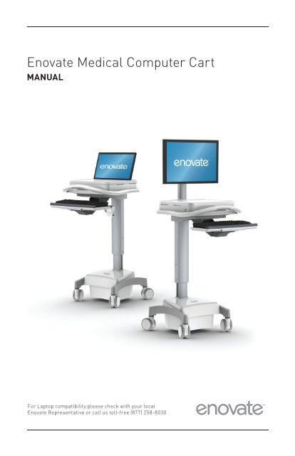
<strong>Enovate</strong> <strong>Medical</strong> Computer <strong>Cart</strong><br />
MANUAL<br />
For Laptop compatibility please check with your local<br />
<strong>Enovate</strong> Representative or call us toll-free (877) 258-8030
The <strong>Enovate</strong> Computer <strong>Cart</strong> was designed to set a new standard in quality. <strong>Enovate</strong>’s goal is to<br />
provide a cart that is built right, ready for years of use, and backed by a commitment of exemplary<br />
service and support.<br />
Thank you for purchasing the<br />
<strong>Enovate</strong> Computer <strong>Cart</strong><br />
For laptop compatibility please check with your local<br />
<strong>Enovate</strong> Representative or call us toll-free (877) 890-6131<br />
1
IMPORTANT WARNINGS:<br />
GROUNDING<br />
Connect the <strong>Enovate</strong> Computer <strong>Cart</strong> to an equivalent receptacle marked “Hospital Only” or “Hospital<br />
Grade” to ensure ground.<br />
SERVICE AND REPLACEMENT<br />
Do not attempt to service or replace any part of the <strong>Enovate</strong> Medication <strong>Cart</strong> unless directed to do so<br />
through <strong>Enovate</strong> approved documentation (i.e., this User <strong>Manual</strong> or other instructions). Only <strong>Enovate</strong><br />
or an <strong>Enovate</strong>-certified entity may service or replace the cart components. If any component on the<br />
cart is missing or damaged, the cart must not be used. Contact <strong>Enovate</strong> immediately to request<br />
service.<br />
DANGEROUS VOLTAGE<br />
Do not remove battery drawer—there may be live parts inside, even when the <strong>Enovate</strong> Medication<br />
<strong>Cart</strong> is turned off.<br />
DO NOT OPEN THE POWER SYSTEM. Unauthorized personnel opening the power system may cause<br />
injury and/or death. If the unit is not working properly, please contact <strong>Enovate</strong>.<br />
DO NOT USE THE UNIT IN OR NEAR WATER OR OTHER LIQUIDS.<br />
If the unit becomes wet, unplug it immediately, wipe away any excess liquid and allow it to dry before<br />
use.<br />
Failure to do so can result in injury and/or death.<br />
For laptop compatibility please check with your local <strong>Enovate</strong> Representative or call us toll-free<br />
(877) 890-6131 Unauthorized personnel opening the battery may cause injury and/or death. If the<br />
unit is not working properly, please contact <strong>Enovate</strong> Customer Service toll free at 877.258.8030<br />
or by email at support@enovateit.com.<br />
2
1<br />
2<br />
4<br />
6<br />
8<br />
10<br />
12<br />
16<br />
22<br />
TABLE OF CONTENTS • MANUAL<br />
WELCOME<br />
WARNINGS<br />
CART FEATURES<br />
TECHNICAL DATA<br />
SAFETY<br />
UNPACKING<br />
INITIAL SET-UP<br />
POWER SYSTEM<br />
WARRANTY<br />
3
<strong>Cart</strong> Features<br />
12” Height Adjustment<br />
4<br />
6” Height Adjustment
OPTIONAL ACCESSORIES<br />
PURELL® Holder<br />
Sharps Container Bracket<br />
File Holder Bracket<br />
Clam Shell<br />
Mouse Holder<br />
<strong>Cart</strong> Features • MANUAL<br />
Side Mount<br />
Mouse Holder<br />
Wipes Bracket<br />
Scanner Bracket<br />
5
Technical Data<br />
OPTIONAL AcceSSORIeS:<br />
The EMC tray has a 12” D x 15.5” W x 2.5”D space to house Laptops or CPU’s. NOTE:<br />
Cables and peripherals must be accounted for when determining appropriate dimensional<br />
parameters. Please account for these dimensions.<br />
6
Ac POWeR SySTeM – TRIPP-LITE UPS INPUT- 120V-60Hz, 5.1 A<br />
• Output- 120V-60Hz, Maximum of 400VA or 300W<br />
• Battery System–12V 40Ah Deep Cycle SLA-AGM<br />
Technical Data • MANUAL<br />
• The powered EMC includes a hospital grade 3-input 5-15 NEMA AC power cord set.<br />
• LCD Parameters – The monitor pole can support weight ranging from 5-16 Lbs.<br />
• Dimensions – The monitor pole can support up to a 22” diagonally measured LCD<br />
• Tray Parameters– Interior usable dimensions (For laptop or CPU storage)<br />
INTeGRATION KIT – THIS kIT INCLUDES:<br />
• Rubber bumpers for keyboard retention<br />
• 18” USB A to USB B Cable<br />
• 8” zip ties<br />
• Pair of keys<br />
• Cable management cover (for LCD units only)<br />
• Powered Control Board (See Below)<br />
FRONT<br />
BAcK<br />
Powered Control Board and USB Hub – Each powered cart includes a 3 input USB<br />
adapter. In laptop versions this USB hub also functions as risers to adjust the height of<br />
the monitor.<br />
7
Safety<br />
GROUNDING<br />
Connect the <strong>Enovate</strong> Medication <strong>Cart</strong> to an equivalent receptacle marked “Hospital<br />
Only” or “Hospital Grade” to ensure ground.<br />
SeRVIce AND RePLAceMeNT<br />
Do not attempt to service or replace any part of the <strong>Enovate</strong> Medication <strong>Cart</strong> unless directed<br />
to do so through <strong>Enovate</strong> approved documentation (i.e., this User <strong>Manual</strong> or other<br />
instructions). Only <strong>Enovate</strong> or an <strong>Enovate</strong>-certified entity may service or replace the<br />
cart components. If any component on the cart is missing or damaged, the cart must<br />
not be used. Contact <strong>Enovate</strong> immediately to request service.<br />
DANGeROUS VOLTAGe<br />
Do not remove battery drawer—there may be live parts inside, even when the <strong>Enovate</strong><br />
Medication <strong>Cart</strong> is turned off.<br />
DO NOT OPeN THe POWeR SySTeM<br />
Unauthorized personnel opening the power system may cause injury and/or death. If the<br />
unit is not working properly, please contact <strong>Enovate</strong>.<br />
DO NOT USe THe UNIT IN OR NeAR WATeR OR OTHeR LIQUIDS<br />
If the unit becomes wet, unplug it immediately, wipe away any excess liquid and allow it<br />
to dry before use.<br />
Failure to do so can result in injury and/or death.<br />
8
Unpack Unpacking<br />
1 2<br />
Before removing the EMC<br />
from a shipping container<br />
check over the packaging<br />
and pallet to prevent<br />
accepting an item with<br />
shipping damage.<br />
3<br />
Remove cardboard lid and<br />
cardboard spacers.<br />
Use scissors or a utility<br />
knife to cut and remove<br />
the two outer straps.<br />
9
Unpack • MANUAL<br />
10<br />
4 5<br />
Remove cardboard walls<br />
and plastic bag. NOTE:<br />
This step requires two<br />
people. Lift cart (with<br />
foam castor braces still<br />
attached) out of the cardboard<br />
base.<br />
6<br />
Open tray and check for<br />
integration kit and locate all<br />
optional accessories.<br />
Remove foam<br />
castor braces.
Initial Setup<br />
The initial setup of the EMC is minimal; incorporate hardware and devices and the cart<br />
is ready to run. The LCD/Laptop installation is intuitive and the EMC includes provisions<br />
to make this experience simple.<br />
LcD cART INTeGRATION<br />
Using the hardware provided with the monitor mount the monitor to the VESA plate of<br />
the monitor pole.<br />
11
Initial Setup • MANUAL<br />
12<br />
• Connect the monitor’s power cable and video cable (DVI, VGA). Route the cable<br />
through the channel on the back of the monitor pole. Slide the cable management<br />
cover into place over the wires (image shows sequence; both bottom prongs in then<br />
the length of one entire side then the other). Leave enough slack above the cable<br />
management strip to allow the monitor to extend fully upward.<br />
• Put the CPU side of the power and video cables through the hole in the center rear<br />
of the tray. Pull any extra cable length into the tray.<br />
• Set the CPU into the tray. Two pieces of Dual Lock (Velcro) are provided to secure<br />
the CPU to the tray. NOTE: Take care in CPU placement; consider orientation based<br />
on direction of cable inputs and sizes INCLUDING monitor input, power input, mouse,<br />
keyboard and any peripherals. Make cable connections within the tray.<br />
• Monitor to CPU, monitor to power and CPU to power. Using the provided USB A to<br />
USB B connects the CPU (“A” connector) to the USB hub (“B” connector). Using the<br />
provided zip ties neatly manage the excess wires within the tray.
LAPTOP cART INTeGRATION<br />
Initial Setup • MANUAL<br />
• Open tray by lifting lid. Plug in Laptop power brick to power source (wc) and plug<br />
into the Laptop.<br />
• Using the provided USB A to USB B connects the Laptop (“A” connector) to the USB<br />
hub (“B” connector).<br />
• Estimate location of USB hub/Laptop riser. Moving the riser towards the front of<br />
the tray will lift the Laptop screen higher while moving the riser towards the back<br />
of the tray will drop the laptop screen lower.<br />
• Slide the Laptop screen through the tray top (as shown). Set the laptop into place<br />
upon the riser and close the lid.<br />
MOUSe INSTALLATION<br />
• Pull the keyboard tray forward to full extension. This will simulate the full length<br />
requirement of Mouse cable length.<br />
• Route the cable under and through the tray, plug into appropriate location on CPU/<br />
Laptop and zip tie into place.<br />
• Stow mouse in mouse holder.<br />
KeyBOARD INSTALLATION<br />
• Apply silicone bumpers to rear corners of the key board tray for retention (with<br />
negative tilt).<br />
• Pull the keyboard tray forward to full extension. This will simulate the full length<br />
requirement of Keyboard cable length.<br />
• Set the Keyboard upon the Keyboard tray.<br />
• Route the cable under and through the tray, plug into appropriate location on CPU/<br />
Laptop.<br />
13
Initial Setup • MANUAL<br />
Power System<br />
SLA cONTROL PANeL<br />
14<br />
Low Battery Alarm Mute<br />
<strong>Cart</strong> Power ON/OFF<br />
Computer Reboot<br />
<strong>Cart</strong> On/Off Indicator Charge Indicator<br />
Work Light ON/OFF<br />
Battery Fuel Gauge<br />
• Power button ON – press and hold for 2 seconds. The first two LEDs will illuminate<br />
amber then the fuel gauge will beep and power on, revealing a charge level (as<br />
described in table 1 below). OFF – press and hold for 1 second. The fuel gauge will<br />
beep and LEDs will power off.<br />
• Power Alert Mute Button If the battery level falls below 60% charge an alarm will<br />
sound; this button will turn it off. See table 1 below for details.<br />
• Battery LeD Fuel Gauge The first LED displays power on/ power off. LEDs two<br />
through five indicate charge level and correspond to a percent range as described<br />
in tables below.<br />
• LeD Work Light Button On/Off toggle for LED work light. If left on, the light will<br />
auto-shut off after five minutes.<br />
• computer Reboot Button (OPTIONAL) Can function as a remote reboot button or<br />
a power toggle button. Extra hardware, found in OPTIONAL ACCESSORIES, and<br />
compatible hardware are required for function.<br />
INITIAL POWeR-UP<br />
Before the initial power up and use the EMC cart must be charged for 24 continuous<br />
hours to insure maximum battery life. Equipment may be connected during this time.
SLA cHARGe LeVeL INDIcATORS (DIScHARGING)<br />
Battery Charge LED Meter Display<br />
Approximate<br />
Low<br />
Battery Module<br />
Battery<br />
Charge Level<br />
Battery Charge LED Meter Display<br />
Alarm*<br />
90%-100%<br />
Approximate<br />
Green<br />
Green Green Green<br />
OFF<br />
Low<br />
60%-89%<br />
Battery Module<br />
Green<br />
Green Green<br />
OFF<br />
Battery<br />
OFF<br />
31%-59%<br />
Charge Level<br />
Yellow<br />
Yellow<br />
OFF<br />
OFF<br />
Alarm*<br />
ON<br />
Power System • MANUAL<br />
eON PHOSPHATe FUeL GAUGe<br />
16<br />
Low Battery Alarm Mute<br />
<strong>Cart</strong> Power ON/OFF<br />
Computer Reboot<br />
<strong>Cart</strong> On/Off Indicator Charge Indicator<br />
Power System • MANUAL<br />
Work Light ON/OFF<br />
Battery Fuel Gauge<br />
• cart Power Button – To turn ON, press and hold for 2 seconds. The first two LEDs<br />
will illuminate amber then the fuel gauge will beep and power on, revealing a<br />
charge level. To turn OFF – press and hold for 1 second. The fuel gauge will beep<br />
and LEDs will power off.<br />
• Low Battery Alarm Mute Button If the battery level falls below 10% charge an<br />
alarm will sound; this button will turn it off.<br />
• Battery Fuel Gauge - The first LED displays power on/ power off. LEDs two through<br />
five indicate charge level.<br />
• Work Light Button - On/Off toggle for LED work light. If left on, the light will<br />
auto-shut off after five minutes.<br />
• computer Reboot Button (OPTIONAL) Can function as a remote reboot button or<br />
a power toggle button. Extra hardware, found in OPTIONAL ACCESSORIES, and<br />
compatible hardware are required for function.<br />
INITIAL POWeR-UP<br />
Before the initial power up and use the EMC cart must be charged for 12 continuous<br />
hours to insure maximum battery life. Equipment may be connected during this time.
Power System • MANUAL<br />
eON PHOSPHATe cHARGe LeVeL INDIcATORS (DIScHARGING)<br />
Charge Level Indicators (Discharging)<br />
Charge Level Indicators (Discharging) Battery Charge LED Meter Display<br />
Approximate<br />
Low<br />
Battery Charge LED Meter Display<br />
Battery Module<br />
Battery<br />
Approximate<br />
Low<br />
Charge Level<br />
Alarm*<br />
Battery Module<br />
Battery<br />
Charge 90%-100% Level Green<br />
Green Green Green Alarm* OFF<br />
60%-89%<br />
Green<br />
Green Green<br />
OFF<br />
OFF<br />
90%-100%<br />
Green<br />
Green Green Green<br />
OFF<br />
30%-59%<br />
Green<br />
Green<br />
OFF<br />
OFF<br />
OFF<br />
60%-89%<br />
Green<br />
Green Green<br />
OFF<br />
OFF<br />
10%-29%<br />
Yellow<br />
OFF<br />
OFF<br />
OFF<br />
OFF<br />
30%-59%<br />
Green<br />
Green<br />
OFF<br />
OFF<br />
OFF<br />
Power System • MANUAL<br />
STORAGe<br />
cAUTION! even after the Power Supply Module is unplugged, its outlets may still<br />
deliver current, until it is disconnected from the Battery Module and completely<br />
turned OFF (deactivated). Before storing your Power Supply Module, make sure the<br />
Battery Module is fully charged. Next, turn the Power Supply Module completely OFF<br />
by following these steps:<br />
18<br />
• Unplug the Power Supply Module from the wall outlet (all LEDs and outlets should<br />
be OFF);<br />
• Disconnect the battery module from the system. If the cart has a medication<br />
cabinet, disconnect the battery in the medication cabinet as well.Press and hold<br />
the “Power” button for at least one second to dissipate any hazardous electrical<br />
charges that might remain inside the Power Supply Module (the Power Supply<br />
Module will click and the alarm may beep briefly).<br />
• If you store the Power Supply Module and Battery Module for an extended period<br />
of time, recharge the Battery Module once per month. If the cart has a medication<br />
cabinet, the cart must be left on while charging, and must be charged for at least<br />
12 hours. This ensures the backup battery gets a full charge.<br />
• Follow the connection and recharge procedure in the “Connection / Start-Up”<br />
section. If you leave the Battery Module discharged for an extended period of<br />
time, it will suffer a permanent loss of capacity.<br />
TROUBLESHOOTING<br />
No AC output power<br />
available at outlets.<br />
Battery Module not<br />
recharging even with AC<br />
utility power present.<br />
Low battery alarm sounding.<br />
Turn Unit On: Turn the Power Supply Module ON using the “Power” button.<br />
Check Connections: Check to make sure the Power Supply Module and Battery<br />
Module are properly connected. Also, make sure the RUI is connected to the<br />
Power Supply Module. The Power Supply Module will not supply AC power<br />
without these connections. The user may need to turn on the Power Supply<br />
Module manually (using the RUI’s “Power” button) after reconnection.<br />
Recharge Battery Module: if the Battery Module is fully discharged, the<br />
Power Supply Module will be unable to supply output power through its<br />
AC Outlets. Allow the battery fully charge.<br />
Check Connection: Check to make sure the Power Supply Module and<br />
Battery Module are properly connected. Also, make sure the Power Supply<br />
Module’s power cord is plugged into a live AC wall outlet.<br />
Replace Battery Module: The Battery Module will reliably supply backup power<br />
for several years with the Lithium Ion and several months for the SLA. When<br />
the battery module reaches then of its service life it will supply progressively<br />
diminishing capacity. Contact <strong>Enovate</strong> for additional information.<br />
Check Battery Charge Level LED Meter: Silence the alarm, if desired, with<br />
the “Alarm Mute” button. Check LED meter to determine the percentage<br />
of charge remaining. When the charge level falls below 10%, the Battery<br />
Module is nearly depleted and Power Supply Module shutdown is imminent.<br />
The user should save open files and safely shutdown connected equipment<br />
immediately. If the cart is unattended and PowerAlert Software is loaded<br />
on a computer connected to the Power Supply Module, PowerAlert will<br />
automatically save open files prior to automatic shutdown.
FReQUeNTLy ASKeD QUeSTIONS<br />
Power System • MANUAL<br />
What is the LeD Fuel Gauge<br />
The LED Fuel Gauge has 5 LEDs: One On/Off LED on the far left and four battery level<br />
LEDs, position 1 – 4 from left to right and indicating low to high from left to right.<br />
What is the status of the unit when the unit is plugged in, Ac LeD is on and 4 Battery<br />
lights (solid green) are on?<br />
With the LEDs in this configuration and the unit plugged in, it is indicated that the unit<br />
is on and that the battery is fully charged (90 – 100%). The unit will pass power to the<br />
connected equipment using utility power. Your unit is functioning properly.<br />
What is the status of the unit when it is plugged in, Ac LeD is off and 4 Battery lights<br />
(solid green) are on?<br />
With the LEDs in this configuration and the unit unplugged it is indicated that the unit is<br />
off and that the battery is fully charged (90 – 100%). The unit will not pass power to the<br />
connected equipment using battery power. Your unit is functioning properly.<br />
What is the status of the unit when it is plugged in, Ac LeD is on, 3 Battery lights (solid<br />
green – position 1, 2 and 3) are on and the 4 th position Battery light flashing?<br />
With the LEDs in this configuration and the unit plugged in, it is indicated that the unit is<br />
on and that the battery is 60 – 89% charged. The unit is currently charging and will pass<br />
power to the connected equipment using utility power. Your unit is functioning properly.<br />
What is the status of the unit when the unit is plugged in, Ac LeD off and 3 Battery lights<br />
(solid green – position 1, 2 and 3) are on and the 4 th position Battery light flashing?<br />
With the LEDs in this configuration and the unit unplugged it, is indicated that the<br />
unit is off and that the battery is 60 – 89% charged. The unit will not pass power to<br />
the connected equipment using battery power. Your unit is functioning properly.<br />
What is the status of the unit when the unit is plugged in, Ac LeD is on and 2 Battery<br />
lights (solid green – position 1 and 2) are on?<br />
With the LEDs in this configuration and the unit plugged in indicates that the unit is on<br />
and that the battery is 31 – 59% charged. The unit is currently charging and will pass<br />
power to the connected equipment using utility power. Your unit is functioning properly.<br />
What is the status of the unit when the unit is plugged in, the Ac LeD is off, 2 Battery<br />
lights (solid green – position 1 and 2) are on and the 4 th position Battery light flashing?<br />
With the LEDs in this configuration and the unit unplugged indicates that the unit is off<br />
and that the battery is 31 – 59% charged. The unit will not pass power to the connected<br />
equipment using battery power. Your unit is functioning properly.<br />
What is the status of the unit when the unit is plugged in, the Ac LeD on and 1 Battery<br />
light (solid green – position 1) is on?<br />
With the LEDs in this configuration and the unit plugged in indicates that the unit is on<br />
and that the battery is equal to/less than 30% charged. The unit is currently charging and<br />
will pass power to the connected equipment using utility power. Your unit is functioning<br />
properly.<br />
What is the status of the unit when the unit is plugged in, the Ac LeD off, 1 Battery<br />
light (solid green – position 1) is on and the 4 th position Battery light is flashing?<br />
With the LEDs in this configuration and the unit unplugged indicates that the unit is<br />
in standby mode and that the battery is equal to/less than 30% charged. The unit is<br />
charging but will not pass power to the connected equipment using battery power. To<br />
pass power to the connected equipment the unit must be turned on (Online mode). Your<br />
unit is functioning properly.<br />
19
Warranty<br />
WHAT'S COVERED AND HOW LONG?<br />
Standard warranty covers four (4) – years structural components, two (2) - years for power system<br />
and electronics, six (6) - months for SLA Battery and three (3) - years for EON Phosphate battery after<br />
purchase. Warranty coverage begins on product’s date of invoice. Standard warranty does not cover<br />
problems resulting from product abuse, negligence/accident, misuse, improper operation, post-delivery<br />
physical damage, and/or product modifications without <strong>Enovate</strong>’s prior written approval. External<br />
peripherals (including: computing equipment/devices, monitors, keyboards, mouse, USB hub, etc.) are<br />
not included in this warranty. <strong>Enovate</strong> shall not be liable for any consequential or incidental damages.<br />
HOW WE HELP YOU<br />
Support services provided along with the standard warranty must be requested within the expressed<br />
warranty time frame for the product element. Technical support may request customer collaboration<br />
and assistance during diagnosis to provide for next business day service as needed. Typically, this<br />
requires, but is not limited to:<br />
• Identifying a primary contact representative (with phone number and e-mail address) to work with<br />
<strong>Enovate</strong> and answer relevant questions. Providing the serial ID number and access to the product.<br />
• Performing basic troubleshooting activities as directed by <strong>Enovate</strong>’s Technical Support.<br />
Resolution methods can include, but are not limited to, any of the following:<br />
• Verbal/written instructions to correct the problem.<br />
• Shipping of replacement parts OR a product swap.<br />
• On-site dispatch of an <strong>Enovate</strong> authorized service technician.<br />
If needed, <strong>Enovate</strong> will involve its design engineers or supplier partners for resolution assistance and<br />
customer’s satisfaction. Determination for resolving warranty issues will be at <strong>Enovate</strong>’s sole<br />
discretion.<br />
TECHNICAL SUPPORT ASSISTANCE<br />
Service requests can be made at any time via <strong>Enovate</strong>’s support website or by phone:<br />
• www.enovateusa.com/support<br />
• 1-877-258-8030 toll-free<br />
• Support Hours are Monday – Friday, 8 am to 5 pm EST (except holidays).<br />
ENOVATE'S SERVICE PLEDGE<br />
Our Customer Care team is located, supported, & operated by <strong>Enovate</strong>'s Michigan<br />
employees in our US headquarters. A reply to all service requests, within two hours of their submittal<br />
during business hours. On-site Parts / Service by the next business day as needed. <strong>Enovate</strong><br />
Authorized Service Technicians are located at more than 400 locations across the United States.<br />
CLEANING INSTRUCTIONS<br />
• Use non abrasive cleaners or mild cleaning solutions. Do not use abrasive cleaners, solvents,<br />
polishes, waxes or steam cleaning tools.<br />
• As a precaution to test the suitability of a cleaning product, apply to an inconspicuous area,<br />
minimizing the time of exposure and the amount of cleaning agent (diluting as recommended by the<br />
supplier) in order to prevent any damage to the surface.<br />
• Contamination by intensively colored substances, for example coffee, mustard, curry or red wine,<br />
have to be removed immediately.<br />
20
7820 N. Lilley Road<br />
Canton, MI 48187<br />
p. (248)655-0548 f. (847)890-6131<br />
www.enovateit.com<br />
support@enovateit.com<br />
©2011 <strong>Enovate</strong>IT LLC. All Rights Reserved