MOULDED CASE CIRCUIT BREAKER (MCCB) - Standard Electricals
MOULDED CASE CIRCUIT BREAKER (MCCB) - Standard Electricals
MOULDED CASE CIRCUIT BREAKER (MCCB) - Standard Electricals

Create successful ePaper yourself
Turn your PDF publications into a flip-book with our unique Google optimized e-Paper software.
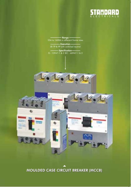
Range<br />
25A to 1600A in different frame sizes<br />
Execution<br />
SP, TP & FP with switched neutral<br />
Specification<br />
IS : 13947-1 & 2 IEC : 60947-1 & 2<br />
<strong>MOULDED</strong> <strong>CASE</strong> <strong>CIRCUIT</strong> <strong>BREAKER</strong> (<strong>MCCB</strong>)
<strong>MCCB</strong><br />
Introduction<br />
The STANDARD range of Moulded Case Circuit Breakers (<strong>MCCB</strong>s) are designed for<br />
circuit protection of low voltage distribution system.They are suitable for application<br />
as main breakers and for protection of branch and feeder circuit & connected<br />
equipments / load.<br />
These <strong>MCCB</strong>s provide overload and short circuit protection for all circuit elements.<br />
They are designed for use in Switchboards, Control Panels, Combination Starters,<br />
in separate enclosures and meet the requirements of lighting, distribution and<br />
power circuits.<br />
<strong>Standard</strong> <strong>Electricals</strong> Ltd. (SEL) offers a comprehensive range of <strong>MCCB</strong>s employing<br />
world class technology and fully conforms to the latest IEC-60947-1& 2/IS-13947-<br />
1& 2.<br />
The <strong>MCCB</strong> comprises of switching mechanism, contact system, arc extinguishing<br />
device and tripping unit all contained in a compact Moulded Case and Cover.<br />
The insulating case and cover are made of high strength, heat resistant, flame retardant resin bonded thermo setting material<br />
which provides:-<br />
<br />
<br />
<br />
<br />
Interphase insulation of a high dielectric strength, making the <strong>MCCB</strong> considerably compact and light weight.<br />
The insulated enclosure with high withstand capacity against thermal and mechanical stresses.<br />
Protection against secondary fire hazards.<br />
Increased safety of operating personnel.<br />
Features<br />
Comprehensive range : 25A - 1600A in different frame sizes.<br />
Compact dimension - space economy.<br />
Identical front plate cut out - lends uniformity.<br />
Interchangeable line & load connection -Offers flexibility of mounting.<br />
Inner view of <strong>MCCB</strong><br />
Adjustable / front accessible thermal and magnetic setting. (Thermal setting for overload adjustable from 70% - 100% of<br />
the rated current & magnetic setting for short circuit adjustable 4-10 times / 5-10 times).<br />
Available in Single pole, 3 pole and 4 pole with switched neutral version.<br />
Suitable for use as Switch Disconnectors / Isolators.<br />
Trip Free Mechanism - The breaker trips internally in case of fault, even if the knob is in the ON position.<br />
O<br />
Mounting possible in vertical or horizontal position or ± 15 in vertical plane.<br />
Complete range of accessories. (Under Voltage Release, Shunt Trip, Auxiliary Switches, Rotary Handles, Extended<br />
Terminals, Back Studs, Phase Barriers, Terminal Shrouds, Enclosures and Earth Leakage Relay).<br />
Technical Data<br />
<strong>Standard</strong> conformity : IEC 60947-1& 2/IS:13947-1 & 2<br />
Rated Operational Voltage : 415V AC<br />
Rated Insulation Voltage : 690V AC<br />
Type of release : Theromagnetic<br />
Utilisation category : A<br />
Rated Frequency : 50/60Hz<br />
Ambient temp. :<br />
O O<br />
40 C (50 C on request)<br />
Operating altitude : 2000 meters<br />
Humidity : 0 - 90%<br />
Rated Impulse Voltage : 8 KV<br />
Electrical & Mechanical Life<br />
Rated Current (A) Mechanical Life Electrical Life<br />
In 00 8500 1500<br />
100< In 315 7000 1000<br />
315< In 630 4000 1000<br />
630< In 800 2500 500<br />
Technical Specifications<br />
FRAME SKB-1 SKB-2 SKB-3 SKB-4 SKB-0<br />
No. of Poles 1P/3P/4PwSN 1P/3P/4P wSN 3P/4P wSN 3P/4P wSN 3P/4PwSN<br />
<strong>Standard</strong> current range/rating(I ) A 25-200* 25-250* 160-800* 160-800* 800-1600*<br />
n<br />
Thermal release setting(Adjustable) 70-100% 70-100% 70-100% 70-100% 70-100%<br />
of I of I of I of I of I of I<br />
n n n n n n<br />
Magnetic release setting Fixed Fixed Adjustable Adjustable Adjustable<br />
for current rating(25A-63A) 400A 400A – – –<br />
for current rating(80A-125A) 800A 800A – – –<br />
for current rating(160A-250A) 1600A 1600A – – –<br />
for current rating(160A-320A) 5-10 times I 5-10 times I –<br />
n n<br />
for current rating(400A-800A) – – 4-10 times I 4-10 times I<br />
n n<br />
for current rating(800A-1600A) – – – – 4000-10000A<br />
Rated short circuit making<br />
capacity (Peak) I KA 52.5 32 73.5 52.5 73.5 105 105<br />
cm<br />
Rated ultimate short circuit (25-125A) (160-200A) (25-125A) (160-250A)<br />
breaking capacity (Icu), kA 240V 40 25 50 40 50 70 70<br />
(At different voltage) 380V 35 16 35 35 35 50 50<br />
415V 25 16 35 25 35 50 50<br />
500V 18 12 25 18 25 35 35<br />
Weight TP (Triple Pole) Kg. 1.8 1.8 9.2 9.2 17#/19**<br />
FPwSN (4 pole<br />
switched neutral) Kg. 2.4 2.4 11.6 11.6 22/25<br />
Terminal capacity (Cable) (Sq.mm) 70 (upto 100A)/150 (125A-250A) – – –<br />
(Bus bar width) (mm) 25 (125 to 200Amp.) 40 40 45** upto 800A<br />
45** upto 1000A<br />
60** upto 1250A<br />
65** upto 1600A<br />
35*.5# upto 1600A<br />
Recommended Torque (Nm) 10 10 – – –<br />
*Current Ratings for SKB-1 & SKB-2 : 25A, 32A, 50A, 63A, 80A, 100A, 125A, 160A, 200A, 250A<br />
for SKB-3 & SKB-4 : 160A, 200A, 250A, 315A, 400A, 500A, 630A, 800A<br />
for SKB-0 : 1000A, 1250A, 1600A<br />
# Terminals at back / rear ** Terminals in front
<strong>MCCB</strong><br />
Technical Specifications<br />
FRAME SKB-5 SKB-6 SKB-7<br />
No. of Poles 1P/3P/4P wSN 1P/3P/4P wSN 3P/4P wSN<br />
<strong>Standard</strong> current range/rating(I n)<br />
A 25-125* 25-125* 25-100*<br />
Thermal release setting Fixed Fixed Fixed<br />
Magnetic release setting Fixed Fixed Fixed<br />
for current rating (25A-50A) 500A 500A 500A<br />
for current rating (63A-80A) 800A 800A 800A<br />
for current rating (100A-125A)<br />
Rated short circuit making<br />
1000A 1000A 1000A<br />
capacity (Peak) Icm kA<br />
Rated ultimate short circuit<br />
17 32 52.5<br />
breaking capacity (Icu), kA 240V 25 25 30<br />
(At different voltages) 380V 10 16 25<br />
415V 10 16 25<br />
500V 7.5 12 14<br />
Weight SP (Single Pole) Kg. 0.35 0.35 –<br />
Weight TP (Triple Pole) Kg. 0.93 0.93 0.93<br />
FPWSN (Four Pole Switched Neutral) Kg. 1.2 1.2 1.2<br />
Terminal capacity (Cable) (Sq.mm) 70 70 70<br />
(Bus bar width) (mm) 10 10 10<br />
Recommended Torque (Nm) 2.5 2.5 2.5<br />
*Current Ratings 25A, 32A, 50A, 63A, 80A, 100A, 125A<br />
Technical Specifications<br />
FRAME SKB-8 SKB-9<br />
No. of Poles 3P/4PwSN 3P/4PwSN<br />
Current Rating (in) A 25-250* 25-250*<br />
Thermal Release Setting Fixed Fixed<br />
Magnetic Release Setting Fixed Fixed<br />
for current rating (25-32A) 500A 500A<br />
for current rating (50-80A) 800A 800A<br />
for current rating (100-125A) 1250A 1250A<br />
for current rating (160-250A)<br />
Rated short circuit making<br />
1600A 1600A<br />
Capacity (Peak) I cm kA<br />
Rated ultimate short circuit<br />
73.5 105<br />
breaking capacity (Icu), kA at 240V 50 70<br />
380V 35 50<br />
415V 35 50<br />
500V 25 35<br />
Weight TP Kg./FPwSN 2.9/3.8 2.9/3.8<br />
Terminal Capacity (Cable) Sq. mm 185 185<br />
(Bus Bar width) mm 18 18<br />
*Current Ratings 25A, 32A, 50A, 63A, 80A, 100A, 125A, 160A, 200A, 250A<br />
257.2<br />
232<br />
Internal Accessories<br />
FRAME SKB-1 SKB-2 SKB-3 SKB-4 SKB-5 SKB-6 SKB-7 SKB-8 SKB-9 SKB-0<br />
Auxiliary Switch(1 C\O or 2C\O) * * * * * * * * * *<br />
Shunt trip * * * * * * * * * *<br />
Under Voltage Release * * * * * * * * * *<br />
External Accessories<br />
FRAME SKB-1 SKB-2 SKB-3 SKB-4 SKB-5 SKB-6 SKB-7 SKB-8 SKB-9 SKB-0<br />
Earth Fault Relay * * * * * * * * * *<br />
Rotary Handle * * * * * * * * * *<br />
Back Studs * * * - - - - * * *<br />
Extended Terminals + + + + + + + + + *<br />
Dolly Extension - - * * - - - - - *<br />
Phase Barriers + + + - + + + + + *<br />
Terminal Shrouds * * - - * * * * * -<br />
Dolly Pad locking Device<br />
* Available<br />
– Not Available<br />
* * * * * * * * * *<br />
+ Supplied along with <strong>MCCB</strong> as standard. (Extended terminal supplied above 100A)<br />
Dimensional Details (in mm)<br />
SKB-1/2<br />
112<br />
100<br />
35 35<br />
35<br />
105<br />
Dia. 6.0 (4 Off) Mounting Holes<br />
SKB-3/4<br />
206<br />
70 70<br />
40<br />
70<br />
208<br />
3P<br />
3P<br />
154<br />
112<br />
92<br />
70<br />
136<br />
35 35 35<br />
70<br />
140<br />
Dia. 6.0 (4 Off) Mounting Holes<br />
4PwSN<br />
30<br />
208<br />
70<br />
Fixing Hole<br />
4PwSN<br />
100<br />
135<br />
91<br />
46<br />
45<br />
17<br />
54.5<br />
83<br />
8<br />
24.5 8<br />
52 102<br />
92<br />
25<br />
29<br />
92<br />
40<br />
25<br />
45.5<br />
25<br />
45.5<br />
25<br />
Scale-1.5<br />
35<br />
12.5<br />
3P With Extended Terminals<br />
3P With Extended Terminals<br />
B B B<br />
A A<br />
DIA 10.0 HOLES<br />
160-400A, A=40, B=30<br />
500-800A, A=20, B=50<br />
Scale-1.10<br />
17.5<br />
58.9<br />
375
<strong>MCCB</strong><br />
Dimensional Details (in mm) Dimensional Details (in mm)<br />
SKB-5/6/7<br />
120<br />
44<br />
11.4<br />
20<br />
26.25<br />
1P<br />
SKB-5/6/7<br />
SUITABLE FOR M8 SCREWS<br />
4 HOLES FOR MS SCREWS<br />
120.00<br />
102.00<br />
SKB 8 & 9<br />
12<br />
74<br />
78.6<br />
94.00<br />
35<br />
35 35<br />
104.5<br />
26.25<br />
104.50<br />
26.25 26.25<br />
170 FIXING CTRS.<br />
190 FIXING CTRS. 55<br />
ON<br />
OFF<br />
FIXING CTRS.<br />
26.25<br />
Three Pole<br />
70.5<br />
11.2<br />
33.5<br />
77.5<br />
83.5<br />
96<br />
30 TERMINAL HIGHT<br />
TERMINALS SUITABLE FOR 22mm<br />
WIDE STRIP OR 185mm2 CABLE<br />
94<br />
100<br />
114<br />
135<br />
78.6<br />
94<br />
Fixing hole<br />
26.25<br />
26.25<br />
26.26<br />
78.50<br />
3P<br />
83.50<br />
77.50<br />
71<br />
97.00<br />
83.5<br />
D1A 10.0 HOLES<br />
18<br />
3P with Extended Terminal<br />
38 38<br />
18<br />
26<br />
18<br />
15<br />
Four Pole with Switched Neutral<br />
2 NOS. MOUNTING HOLES FOR M4 SCREWS<br />
Four Pole with Switch Neutral<br />
12.5<br />
SKB 0<br />
Four Pole with Switched Neutral<br />
Three Pole<br />
S. No. Rating A B T<br />
1. 800A 70 45 6x2<br />
2. 1000A 70 45 15<br />
3. 1250A 82 60 15<br />
4. 1600A 87 65 18
<strong>MCCB</strong><br />
<strong>MCCB</strong> Adjustable Type - Three Pole<br />
Rating Cat No.<br />
(Amps.)<br />
SKB-1 SKB-2<br />
25 ISLAST0025 ISLANT0025<br />
32 ISLAST0032 ISLANT0032<br />
50 ISLAST0050 ISLANT0050<br />
63 ISLAST0063 ISLANT0063<br />
80 ISLAST0080 ISLANT0080<br />
100 ISLAST0100 ISLANT0100<br />
125 ISLAST0125 ISLANT0125<br />
160 ISLAST0160 ISLANT0160<br />
200 ISLAST0200 ISLANT0200<br />
250 - ISLANT0250<br />
Rating<br />
Cat No.<br />
(Amps.)<br />
SKB-3 SKB-4 SKB-0<br />
160 ISLCNT0160 ISLCHT0160 –<br />
200 ISLCNT0200 ISLCHT0200 –<br />
250 ISLCNT0250 ISLCHT0250 –<br />
315 ISLCNT0315 ISLCHT0315 –<br />
400 ISLCNT0400 ISLCHT0400 –<br />
500 ISLCNT0500 ISLCHT0500 –<br />
630 ISLCNT0630 ISLCHT0630 –<br />
800 ISLCNT0800 ISLCHT0800 –<br />
1000 – – ISLDNT1000<br />
1250 – – ISLDNT1250<br />
1600 – – ISLDNT1600<br />
<strong>MCCB</strong> Adjustable Type - Four Pole (wSN)<br />
Rating<br />
(Amps.)<br />
Cat No.<br />
SKB-1 SKB-2<br />
25 ISLASF0025 ISLANF0025<br />
32 ISLASF0032 ISLANF0032<br />
50 ISLASF0050 ISLANF0050<br />
63 ISLASF0063 ISLANF0063<br />
80 ISLASF0080 ISLANF0080<br />
100 ISLASF0100 ISLANF0100<br />
125 ISLASF0125 ISLANF0125<br />
160 ISLASF0160 ISLANF0160<br />
200 ISLASF0200 ISLANF0200<br />
250 - ISLANF0250<br />
Rating<br />
Cat No.<br />
(Amps.)<br />
SKB-3 SKB-4 SKB-0<br />
160 ISLCNF0160 ISLCHF0160<br />
–<br />
200 ISLCNF0200 ISLCHF0200 –<br />
250 ISLCNF0250 ISLCHF0250 –<br />
315 ISLCNF0315 ISLCHF0315 –<br />
400 ISLCNF0400 ISLCHF0400 –<br />
500 ISLCNF0500 ISLCHF0500 –<br />
630 ISLCNF0630 ISLCHF0630 –<br />
800 ISLCNF0800 ISLCHF0800 –<br />
1000 – – ISLDNF1000<br />
1250 – – ISLDNF1250<br />
<strong>MCCB</strong> Fixed Type - Single Pole<br />
Rating<br />
(Amps.)<br />
Cat No.<br />
SKB-6<br />
25 ISLGNS0025<br />
32 ISLGNS0032<br />
50 ISLGNS0050<br />
63 ISLGNS0063<br />
80 ISLGNS0080<br />
100 ISLGNS0100<br />
125 ISLGNS0125<br />
<strong>MCCB</strong> Fixed Type - Three Pole<br />
Rating<br />
(Amps.)<br />
SKB-5<br />
Cat No.<br />
SKB-6 SKB-7<br />
25 ISLGST0025 ISLGNT0025<br />
ISLGHT0025<br />
32 ISLGST0032 ISLGNT0032 ISLGHT0032<br />
50 ISLGST0050 ISLGNT0050 ISLGHT0050<br />
63 ISLGST0063 ISLGNT0063 ISLGHT0063<br />
80 ISLGST0080 ISLGNT0080 ISLGHT0080<br />
100 ISLGST0100 ISLGNT0100 ISLGHT0100<br />
125 ISLGST0125 ISLGNT0125 -<br />
Rating<br />
Cat No.<br />
(Amps.) SKB-8 SKB-9<br />
25 ISLFNT0025 ISLFHT0025<br />
32 ISLFNT0032 ISLFHT0032<br />
50 ISLFNT0050 ISLFHT0050<br />
63 ISLFNT0063 ISLFHT0063<br />
80 ISLFNT0080 ISLFHT0080<br />
100 ISLFNT0100 ISLFHT0100<br />
125 ISLFNT0125 ISLFHT0125<br />
160 ISLFNT0160 ISLFHT0160<br />
200 ISLFNT0200 ISLFHT0200<br />
250 ISLFNT0250 ISLFHT0250<br />
<strong>MCCB</strong> Fixed Type - Four Pole (wSN)<br />
Rating<br />
Cat No.<br />
(Amps.) SKB-5 SKB-6 SKB-7<br />
25 ISLGSF0025 ISLGNF0025<br />
ISLGHF0025<br />
32 ISLGSF0032 ISLGNF0032 ISLGHF0032<br />
50 ISLGSF0050 ISLGNF0050 ISLGHF0050<br />
63 ISLGSF0063 ISLGNF0063 ISLGHF0063<br />
80 ISLGSF0080 ISLGNF0080 ISLGHF0080<br />
100 ISLGSF0100 ISLGNF0100 ISLGHF0100<br />
Rating<br />
Cat No.<br />
(Amps.) SKB-8 SKB-9<br />
25 ISLFNF0025 ISLFHF0025<br />
32 ISLFNF0032 ISLFHF0032<br />
50 ISLFNF0050 ISLFHF0050<br />
63 ISLFNF0063 ISLFHF0063<br />
80 ISLFNF0080 ISLFHF0080<br />
100 ISLFNF0100 ISLFHF0100<br />
125 ISLFNF0125 ISLFHF0125<br />
200 ISLFNF0200 ISLFHF0200<br />
250 ISLFNF0250 ISLFHF0250
<strong>MCCB</strong> Accessories<br />
Auxiliary Switch<br />
Frame 1 / 2, 3 / 4, 5/6/7*, 8/9<br />
Frame Size Configuration Cat No.<br />
SKB 1/2 1NO + 1NC ISLLAS1CO<br />
SKB 1/2 2 (1NO + 1NC) ISLLAS2CO<br />
SKB 3/4 1NO + 1NC ISLLASC1CO<br />
SKB 3/4 2 (1NO + 1NC) ISLLASC2CO<br />
SKB 5/6/7 1NO + 1NC ISLLASG1CO<br />
SKB 5/6/7 2 (1NO + 1NC) ISLLASG2CO<br />
SKB 8/9 1NO + 1NC ISLLASF1CO<br />
SKB 8/9 2 (1NO + 1NC) ISLLASF2CO<br />
SKB 0 1NO + 1NC ISLLASD1CO<br />
SKB 0 2 (1NO + 1NC) ISLLASD2CO<br />
*Voltage rating 450Vac/250Vac/250Vdc<br />
*In frame 1/2,3/4,8/9 current rating is 4 Amp.<br />
*In frame 5/6/7 current rating is 3 Amp.<br />
Shunt Trip<br />
Shunt trip is used to trip the breaker electrically from a remote point. Since shunt<br />
trip coil does not have a continuous rating, the coil must be connected to the load<br />
end of the breaker and must not be energised for more than 2 secs.<br />
Coil Voltage Frame Size (Cat No.)<br />
SKB 1/2 SKB 3/4 *SKB 5/6/7 SKB 8/9 SKB 0<br />
12-36 Vdc ISLLSTA030 ISLLSTC030 ISLLSTG030 ISLLSTF030 ISLLSTD030 100-110 Vac ISLLSTA110 ISLLSTC110 ISLLSTG110 ISLLSTF110 ISLLSTD110<br />
220-240 Vac ISLLSTA240 ISLLSTC240 ISLLSTG240 ISLLSTF240 ISLLSTD240<br />
280-415 Vac ISLLSTA415 ISLLSTC415 ISLLSTG415 ISLLSTF415 ISLLSTD415<br />
* For operating the Shunt Trip, one changeover contact of the Aux. switch should be used leaving one free.<br />
Under Voltage Release<br />
Coil Voltage Frame Size (Cat No.)<br />
SKB 1/2 SKB 3/4 *SKB 5/6/7 SKB 8/9 SKB 0<br />
110-120 Vdc ISLUVRA110 ISLUVRC110 ISLUVRG110<br />
ISLUVRF110 ISLUVRD110<br />
220-240 Vac ISLUVRA240 ISLUVRC240 ISLUVRG240 ISLUVRF240 ISLUVRD240<br />
380-440 Vac ISLUVRA440 ISLUVRC440 ISLUVRG240 ISLUVRF440 ISLUVRD440<br />
The breaker trips if the supply voltage dips below 85% of the rated voltage.<br />
The breaker can not be switched ON unless there is a supply to the UVR (NVNC feature).<br />
Supplied with external mounting Power pack to operate on AC supplies in all the frame sizes<br />
Additional transformer is also supplied for 380-440V AC & 110-120V AC.<br />
Rotary Handle<br />
Direct Padlockable With Door interlock and 300mm remote shaft<br />
Frame Size Cat No.<br />
SKB 1/2 ISLLRRHA30<br />
SKB 3/4 ISLLRRHC30<br />
SKB 5/6/7 ISLLRRHG30<br />
SKB 8/9 ISLLRRHF30<br />
SKB 0 ISLLRRHD30<br />
Other External Accessories<br />
Dolly Pad locking device<br />
Extended terminals<br />
Phase Barriers<br />
Dolly Extension<br />
Back Studs<br />
Auxiliary Switch<br />
Under Voltage Release<br />
<strong>MOULDED</strong> <strong>CASE</strong> <strong>CIRCUIT</strong> <strong>BREAKER</strong><br />
Shunt Trip<br />
Rotary Handle & Spares<br />
The earth fault detection system for use with STANDARD <strong>MCCB</strong>s comprises of a core balance transformer (CT) coupled to an<br />
advanced RCD relay. The relay may be used to trip a circuit breaker via a shunt trip or an under voltage release in the event of<br />
an Earth Fault.<br />
The relay and one of the four available CT's is all that is required for a complete earth fault sensing system suitable for the<br />
control of a circuit breaker in a circuit upto 800A fitted with either a shunt trip or an under voltage release. The simple<br />
arrangement and a small number of inter-connection necessary ensure that EFR is easily selected and installed.<br />
The relay is suitable for 220-240V AC supply with the flexibility of choosing the sensitivity between 300mA to 2A and time<br />
delay should be selected by the DIP switches provided on the facia of the relay.<br />
•<br />
•<br />
•<br />
•<br />
•<br />
•<br />
•<br />
•<br />
Earth Fault Relay<br />
Features<br />
No nuisance tripping<br />
DIN rail mounting<br />
Adjustable time delay<br />
Choice of sensitivity from 300mA upto 2A<br />
Trip indication LED(Red)<br />
ON indication LED(Green)<br />
Test push button<br />
Reset push button<br />
Technical Data<br />
Supply Voltage : 220V / 240V AC, 50 / 60Hz<br />
Changeover contact : 5A-15A 240V AC<br />
Sensitivity : 300mA, 500mA, 1A, 2A<br />
Time delay (m.sec.) : 200, 500, 1000, 5000<br />
The earth fault relay is supplied with the CT based on<br />
the current rating. To operate the EFR a shunt trip or<br />
an under voltage release is necessary which has to be<br />
ordered separately.<br />
Coil Voltage Cat No.<br />
25-100 ISEF1100<br />
125-200 ISEF2200<br />
250-400 ISEF3400<br />
500-800 ISEF4800<br />
Core Balance Current Transformer<br />
Black Red<br />
Core Balance<br />
Transformer<br />
220-240 V AC<br />
UVR<br />
Earth Fault Relay<br />
or<br />
Shunt<br />
Trip<br />
1 2 3 4 5<br />
HI LO N E L<br />
220-240 V AC<br />
ON TEST TRIP<br />
0.2<br />
0.5<br />
1<br />
5<br />
I (A)<br />
RESET<br />
EFR RELAY<br />
6 7 8<br />
Not Used<br />
0.3<br />
0.5<br />
1<br />
2<br />
T(s)<br />
N/O P N/C Not Used<br />
9 10 11 12 13 14 15 16<br />
Size <strong>MCCB</strong> Current Rating Internal Dimension<br />
Shape<br />
1. 25-100A 60mm Circular<br />
2. 125-200A 95mm Circular<br />
3. 250-400A 145mm Circular<br />
4. 500-800A 300 x 80 mm Rectangular<br />
5. 1000-1600A On Request Rectangular
<strong>MCCB</strong> Accessories<br />
Dimensional Details (in mm)<br />
General Purpose Enclosure<br />
Enclosures made of special grade CRCA steel are available for housing SKB-1<br />
to SKB-9 Frame <strong>MCCB</strong>s upto 800A. They are manufactured with latest<br />
technology using CNC Punch and Brake presses to attain highest degree of<br />
perfection. The enclosures are painted with latest techniques in powder coating<br />
using epoxy polyester and polyester resin based powder paints to ensure<br />
smooth, scratch resistant surface coatings. They are suitable for wall mounting &<br />
adequate knockouts are provided for cable entry.<br />
Description Cat. No.<br />
SKB-5/6/7 Frame SP ISEGSP<br />
SKB-5/6/7 Frame TP ISEGTP<br />
SKB-5/6/7 Frame FP ISEGFP<br />
SKB-1/2 Frame SP ISEASP<br />
SKB-1/2 Frame TP ISEATP<br />
SKB-1/2 Frame FP ISEAFP<br />
SKB-8/9 Frame TP ISEFTP<br />
SKB-8/9 Frame FP ISEFFP<br />
SKB-3/4 Frame TP (400A) ISECTP<br />
SKB-3/4 Frame FP (400A) ISECFP<br />
SKB-3/4 Frame TP (800A) ISECTP<br />
SKB-3/4 Frame FP (800A) ISECFP<br />
Dimensional Details (in mm)<br />
B<br />
W<br />
A<br />
h<br />
D<br />
H<br />
Description W D h H AxB<br />
SKB-5/6/7 Frame 260 108 360 370 160x360<br />
SKB-1/2 Frame 260 108 560 570 160x480<br />
SKB-8/9 Frame 260 122 560 570 160x480<br />
SKB-3/4 Frame<br />
upto 400 A<br />
440 122 960 975 280x802<br />
SKB-3/4 Frame<br />
upto 800 A<br />
540 122 960 975 380x802<br />
STANDARD <strong>MCCB</strong> DO WNSTREAM DEVICE (LOW SET)<br />
Ambient Temperature Compensation Chart (SKB 1/2, SKB 3/4, SKB 5/6)<br />
COMPENSATION FACTOR (% OF CURRENT RATING, i)<br />
Discrimination Data<br />
0<br />
AMBIENT TEMPERATURE( C)<br />
IS:13703 HBC Fuse - Upstream Device<br />
Ref SKB 0<br />
Ref SKB 1/2<br />
Ref SKB 8/9<br />
Ref SKB 3/4<br />
Ref SKB 5/6/7<br />
Product Rating KA @ Current Rating of HBC Fuses<br />
(A) 415V 80 100 125 160 200 250 315 400 500 630 800<br />
SKB 1/2 25 25 1200 1400 1800 2400 3200 4500 5500 8000 12000 14000 23000<br />
SKB 3/4<br />
32 25 1200 1400 1800 2400 3200 4500 5500 8000 12000 14000 23000<br />
40 25 350 1400 1800 2400 3200 4500 5500 8000 12000 14000 23000<br />
50 25 300 1400 1800 2400 3200 4500 5500 8000 12000 14000 23000<br />
63 25 250 1400 1800 2400 3200 4500 5500 8000 12000 14000 23000<br />
80 25 300 450 2400 3200 4500 5500 8000 12000 14000 23000<br />
100 25 400 650 3200 4500 5500 8000 12000 14000 23000<br />
125 25 550 3200 4500 5500 8000 12000 14000 23000<br />
160 25 650 1300 5500 8000 12000 14000 23000<br />
200 25 1200 1300 8000 12000 14000 23000<br />
250 50 1000 8000 12000 14000 23000<br />
315 50 2000 12000 14000 23000<br />
400 50 2500 14000 23000<br />
500 50 3500 23000<br />
630 50 5500<br />
SKB 0 800 50<br />
6000<br />
The above table gives fault currents in amperes till which level the downstream breakers shall act prior to the upstream fuse.
<strong>MCCB</strong><br />
DISCRIMINATION DATA<br />
STANDARD <strong>MCCB</strong> UPSTREAM DEVICE INSTANTANEOUS TRIP SET AT HIGH<br />
SKB 0<br />
SKB 3/4<br />
SKB 1/2<br />
kA@<br />
Product Rating<br />
1250 1600<br />
1000<br />
800<br />
600<br />
800<br />
630<br />
500<br />
400<br />
315<br />
(A) 415V 25 23 40 50 63 80 100 125 160 ALL 250<br />
8000 7400 8300 9200 9200 9200<br />
6300<br />
3000 4000 5000<br />
SKB 1/2 63 25 800 800 800 1600 1600 2500<br />
9200<br />
9200<br />
9200<br />
8300<br />
8000 7400<br />
6300<br />
3000 4000 5000<br />
2500<br />
80 25 1600 1600<br />
9200<br />
9200<br />
9200<br />
8300<br />
8000 7400<br />
6300<br />
5000<br />
4000<br />
3000<br />
2500<br />
100 25 1600 1600<br />
9200<br />
9200<br />
9200<br />
8300<br />
8000 7400<br />
6300<br />
3000 4000 5000<br />
125 25 1600 1600 2500<br />
SKB 3/4<br />
9200<br />
9200<br />
9200<br />
8300<br />
8000 7400<br />
6300<br />
3000 4000 5000<br />
2500<br />
160 25<br />
9200<br />
9200<br />
9200<br />
8300<br />
8000 7400<br />
6300<br />
5000<br />
3000 4000<br />
2500<br />
200 25<br />
9200<br />
9200<br />
9200<br />
8300<br />
8000 7400<br />
6300<br />
4000 5000<br />
315 50<br />
9200<br />
9200<br />
9200<br />
8300<br />
8000 7400<br />
6300<br />
5000<br />
400 50<br />
9200<br />
9200<br />
9200<br />
8300<br />
8000 7400<br />
6300<br />
500 50<br />
9200<br />
9200<br />
9200<br />
8300<br />
8000 7400<br />
630 50<br />
9200<br />
9200<br />
9200<br />
8300<br />
7400<br />
800 50<br />
9200<br />
9200<br />
9200<br />
SKB 0 1000 50<br />
9200 9200<br />
1250 50<br />
9200<br />
1600 50<br />
The above table gives fault current in amperes till which level the downstream breakers shall act prior to the upstream breaker<br />
Selection & Application<br />
TRANSFORMER PROTECTION<br />
Primary side<br />
For the protection of transformer with a circuit breaker connected<br />
to the primary side (LT primary) the no load inrush current of the<br />
transformer must be considered. The peak value of the first<br />
current wave often reaches 10-15 times the rated current and<br />
may sometimes reach as high as 20-25 times. However, the<br />
transient decays very quickly (in a few m.sec.). Thus the <strong>MCCB</strong><br />
selected should have a magnetic setting which will not be<br />
actuated by the momentary inrush current.<br />
Secondary side<br />
STANDARD <strong>MCCB</strong>s can be used for protection of transformer on<br />
the LT side (secondary side) as an outgoing protective device.<br />
Selection table For Transformer Protection<br />
<strong>MCCB</strong> Rating in Amperes<br />
Transformer SKB-5 SKB-6 SKB-7 SKB-1 SKB-2 SKB-2 SKB-3 SKB-4<br />
Rating (KVA) 10kA 16kA 25kA 25kA 25kA 35kA 35kA 50kA<br />
16 25 25 25 25 25 25<br />
25 40 40 40 40 40 40<br />
63 100 100 100 100 100 100<br />
100 160 160 160 160 160<br />
160 250 250 250 250 250<br />
200 315 315<br />
250 400 400<br />
315 500 500<br />
400 630 630<br />
500<br />
630<br />
750<br />
800 800<br />
GENERATOR Set Protection<br />
STANDARD <strong>MCCB</strong>s can be used for the effective protection and<br />
control of Diesel Generating set against overload and short circuits.<br />
The Current rating of <strong>MCCB</strong> to be selected is calculated as follows :<br />
kVA = 3 U e X Ie<br />
I e = kVA<br />
3x<br />
U e<br />
or<br />
Where,<br />
kVA = Rating of the DG Set<br />
U e = Rated Voltage<br />
I e = Rated Current<br />
The <strong>MCCB</strong> rating selected is greater than or equal to the rated<br />
current value<br />
The rated current of the transformer is calculated as follows :<br />
kVA x 1000<br />
I = Amps<br />
e<br />
3 x U e<br />
‘U e’<br />
is the Rated Voltage at the LT side<br />
The Breaking capacity of the breaker for protection can be<br />
calculated as :<br />
I e<br />
I = x 10 b<br />
Z%<br />
-3 Kiloamperes<br />
Where ‘I b’<br />
is the rated breaking capacity,<br />
‘I e ’ the rated current<br />
‘Z%’ is the percentage impedance of transformer<br />
(specified by the manufacturer)<br />
Selection Table for DG Set Protection<br />
SKB-0<br />
50kA<br />
1000<br />
1200<br />
DG Set Rating (KVA) <strong>MCCB</strong> Rating (Amperes)<br />
16<br />
25<br />
25<br />
40<br />
63<br />
100<br />
10<br />
160<br />
16<br />
250<br />
20<br />
315<br />
25<br />
400<br />
31<br />
500<br />
40<br />
630<br />
63<br />
1000<br />
750<br />
1200
<strong>MCCB</strong><br />
Selection & Application Selection & Application<br />
FEEDER / CABLE PROTECTION<br />
An estimation of the prospective short-circuit current (psc) in an<br />
installation is an important consideration in the selection of the<br />
appropriate protective device.<br />
The magnitude of the short-circuit current (rms value of the AC<br />
component) at a point in the installation will depend upon;<br />
(A) Prospective short-circuit current at the origin of the installation.<br />
(B) The amount of resistance in the circuit between the origin of<br />
the installation and the point at which the short circuit occurs.<br />
(C) The type of short-circuit, phase to phase or phase to earth<br />
or phase to neutral.<br />
It is possible to arrive at a maximum prospective short circuit value<br />
at the origin by taking the transformer kVA rating and its impedance<br />
and calculating from the expression :<br />
SC kA=<br />
Transformer rating (kVA) x 100<br />
3 x Secondary voltage x % impedance of transformer<br />
To calculate the resistance in the LV circuit, obtain details of lengths<br />
and sizes of cables between the source of supply and the point<br />
under calculation. Using the table provided, determine the sum of<br />
cable resistances and then simply read off the estimated fault<br />
current from the relevant transformer curve on the graph.<br />
Typical Installation<br />
The values assume a symmetrical fault across the three phases. In<br />
a single circuit, for line to neutral faults, take the cable resistance<br />
value from the table and double it.<br />
The selection of STANDARD <strong>MCCB</strong> for feeder /cable protection<br />
depends on the total load to be protected and the prospective<br />
short-circuit current (psc) at the point of installation.<br />
PSC at Aapproximately 27kA<br />
PSC at B<br />
resistance A to B (a) 0.30m= 25kA<br />
PSC at C<br />
+resistance A to B 0.30m<br />
+resistance B to C1 10.70m<br />
11.00m = 12kA<br />
PSC at D<br />
+resistance A to B 0.30m<br />
+resistance B to C 10.70m<br />
+resistance C to D 46.00m (b)<br />
57.00m = 3kA<br />
(a) 2 cables per phase divided by 2<br />
(b) 2 core cable, multiplied by 2<br />
The above calculations have an inbuilt safety margin as they<br />
assume a no impedance fault condition which would not be the<br />
case in practice.<br />
Fault Current (kA)<br />
Estimating the Prospective Short Circuit Current<br />
Total Circuit Resistance ( ohm)<br />
Maximum Resistance of Copper Conductors at 20°C ( ohm)<br />
Nominal<br />
Cross-sectional<br />
2 Area<br />
(mm ) Cable Length<br />
5m 10m 15m 20m 30m 40m 50m 60m 70m 80m 90m 100m<br />
1 90.50 181.00<br />
1.5 60.50 121.00 182.00<br />
2.5 37.10 37.10 74.10 111.00 148.00<br />
4 23.10 46.10 69.20 92.20 138.00<br />
6 15.40 30.80 46.20 61.60 92.40 123.00<br />
10 9.15 18.30 27.50 36.60 54.90 73.20 91.50 110.00<br />
16 5.75 11.50 17.30 23.00 34.50 46.00 57.20 69.00 80.50 103.50<br />
25 3.64 7.27 10.90 14.50 21.80 29.10 36.40 43.60 50.90 58.20 65.40 72.70<br />
35 2.62 5.24 7.86 10.48 15.70 21.00 26.20 31.40 36.70 41.90 47.20 52.40<br />
50 1.94 3.87 5.81 7.74 11.60 15.50 19.40 23.20 27.10 31.00 34.80 38.70<br />
70 1.34 2.68 4.02 5.36 8.04 10.70 13.40 16.10 18.80 21.40 24.10 26.80<br />
95 0.96 1.93 2.10 3.86 5.79 7.72 9.65 11.60 13.60 15.40 17.40 19.30<br />
120 0.77 1.53 2.30 3.06 4.59 6.12 7.65 9.18 10.70 12.20 13.80 15.30<br />
150 0.62 1.24 1.86 2.48 3.72 4.96 6.20 7.44 8.68 9.92 11.20 12.40<br />
185 0.49 1.00 1.49 1.98 2.97 3.96 4.96 5.96 6.94 7.93 8.92 9.91<br />
240 0.34 0.75 1.13 1.51 2.26 3.02 3.77 4.52 5.28 6.03 6.79 7.54<br />
300 0.30 0.63 0.90 1.20 1.80 2.80 3.00 3.61 4.21 4.81 5.41 6.01<br />
400 0.23 0.47 0.70 0.94 1.41 1.88 2.35 2.85 3.29 3.76 4.23 4.70<br />
500 0.18 0.37 0.55 0.73 1.10 1.46 1.83 2.20 2.56 2.93 3.29 3.66<br />
630 0.14 0.28 0.42 0.57 0.85 1.13 1.42 1.78 2.15 2.51 2.88 3.25
<strong>MCCB</strong><br />
Selection & Application<br />
Motor Control<br />
STANDARD <strong>MCCB</strong>s can be used for motor protection. Selection of<br />
<strong>MCCB</strong>s has to be done taking into consideration the starting inrush<br />
current, and the system fault levels. Further the selection is also<br />
based on type of starting, i.e. DOL or Star Delta.<br />
DOL Starting<br />
Care is to be taken to avoid nuisance tripping during starting of<br />
Squirrel Cage Motors since the inrush current will be in the order of<br />
600 to 800% of the full load current of the motor. The overload<br />
setting is chosen such that it does not trip during starting.<br />
The figures shown are based on following motor starting conditions : -<br />
Direct online 7 X full load current for 5 seconds.<br />
Star/Delta 4 X full load current for 12 seconds.<br />
Selection table for Motor Protection<br />
Star-Delta Starting<br />
In Star Delta starting of motors, since there is a reduction in the<br />
starting current due to reduced voltage, the <strong>MCCB</strong>s do not have a<br />
problem in the overload setting. But the transient currents can go upto<br />
12 times the rated current during change over from star to delta which<br />
will cause the instantaneous magnetic release to trip the breaker. So<br />
proper selection of magnetic pickup level is important for prevention<br />
of nuisance tripping during change over from Star to Delta.<br />
It is always recommended to select an <strong>MCCB</strong> in co-ordination with<br />
Contactor and Over Load Relay so as to have the best and optimum<br />
benefit of all the devices.<br />
Motor Rating Apprx. Full<br />
Direct On Line<br />
Star/Delta<br />
Load<br />
Current <strong>MCCB</strong> Rating/Type<br />
<strong>MCCB</strong> Rating/Type<br />
HP KW (A) at 415V SKB-1 SKB-3/4 SKB-1 SKB-3/4 SKB-0<br />
10 7.5 14 25 - 25 - -<br />
12.5 9 17 25 - 25 - -<br />
15 11 21 25 - 25 - -<br />
20 15 28 32 - 32 - -<br />
25 19 35 40 - 40 - -<br />
30 22 41 50 - 50 - -<br />
40 30 52 80 - 63 - -<br />
50 37 69 100 - 80 - -<br />
60 45 80 - - 100 - -<br />
75 55 97 - - 125 - -<br />
100 75 125 - - 160 - -<br />
125 90 156 - 250 - - -<br />
150 112 190 - 315 - 250 -<br />
175 130 225 - 315 - 315 -<br />
200 149 255 - 315 - 315 -<br />
220 160 275 - 400 - 400 -<br />
250 186 320 - 400 - 500 600<br />
300 224 375 - 500 - 500 600<br />
350 261 449 - 630 - 630 600<br />
400 298 505 - 630 - 630 600<br />
Selection & Application<br />
Capcitor Control<br />
Capacitor Rating (KvAr)<br />
When a capacitor circuit is opened, it exhibits characteristics<br />
distinctly differently from inductor loads due to the effects of residual<br />
electric charge in the capacitor. The recovery voltage appears<br />
across the contacts immediately after the circuit is opened is equal<br />
to the difference between the capacitor residual voltage and supply<br />
voltage. Therefore half a cycle after the circuit opens, the voltage<br />
between the contacts of the switch rises to twice the supply voltage<br />
or higher.<br />
In a three phase circuit the recovery voltage appearing between the<br />
contacts in the first interrupted phase could rise to as high as 2.5<br />
times the supply voltage. Unless the breaker contacts are fully open<br />
for at least ½ cycle after the capacitor current is interrupted, restrike<br />
of arc is likely to occur. If the restrike arc is repeated, the voltage<br />
could continue to rise to the dielectric breakdown point of the<br />
capacitor. Hence, fast interrupting, quick make, quick-break circuit<br />
breakers should be used for this type of circuit.<br />
When a capacitor circuit is closed a condenser charge q = CU<br />
which corresponds to the instantaneous value ‘U’ of the supply<br />
voltage at closing time, must be instantaneously supplied, causing<br />
a large inrush current to flow through it. If the capacitor circuit is<br />
closed in the voltage phase at which the inrush current is maximum,<br />
the maximum value of the inrush current is approximately,<br />
C<br />
I = x U<br />
p L<br />
The maximum time duration during which the maximum current<br />
flows is about 0.5 ms. Selection of a <strong>MCCB</strong> for capacitor circuit<br />
duty must therefore consider the effects of higher short circuit and<br />
inrush currents. This will affect the choice of instantaneous trip<br />
current rating. In practice, an <strong>MCCB</strong> which satisfies the following<br />
equations should be chosen.<br />
Where :<br />
Ir = Rated current of <strong>MCCB</strong>s<br />
Ic = Rated current of capacitor<br />
Iinst = Short circuit pick up setting of the <strong>MCCB</strong><br />
= Maximum capacitor inrush current<br />
Ip<br />
Ir > 1.5 X Ic<br />
Iinst ><br />
IP<br />
2<br />
It is therefore necessary to select a circuit breaker with current rating<br />
not less than 1.5 - 2.0 times the rated current of the capacitor.<br />
DC CONTROL<br />
<strong>MCCB</strong>s though not separately designed for DC applications are<br />
suitably modified to be able to operate on DC systems also upto<br />
500V DC / 250V DC. This is achieved by modifying for:<br />
i) Current carrying capacity<br />
ii) Over current and short circuit protection<br />
iii) Short circuit breaking capacity (with L/R time constant<br />
limitations)<br />
Current Carrying Capacity<br />
The continuous current carrying capacity is generally a function<br />
limited by the temperature rise of various internal components of<br />
<strong>MCCB</strong>s.<br />
The AC rating of <strong>MCCB</strong>s is expressed as “RMS” value. The DC<br />
rating is “Average” value. The RMS and average value can be<br />
related by a “Form Factor” which is 1.1.<br />
Hence, an AC <strong>MCCB</strong> can be assigned a 10% higher DC current<br />
rating. But in practice the use of DC <strong>MCCB</strong> ratings are equal to AC<br />
ratings and thereby, temperature rise is restricted within limits.<br />
Overload Release & Overload Protection<br />
The overload release are generally thermal type with a Bimetal-<br />
Heater system. The heating effect which can be expressed by the<br />
2 2<br />
factor integral I t varies for AC and DC. The integral (I t) for AC will<br />
2<br />
be 1.21 times integral (I avt) for DC, thus an AC <strong>MCCB</strong> when used<br />
in DC circuit will trip slower. For example a 100A AC <strong>MCCB</strong> when<br />
used in DC circuit for 100A will sense a 20% overload only from<br />
133A onwards.<br />
To retain the same Overload characteristics as AC, it is important to<br />
separately calibrate the <strong>MCCB</strong>s for DC ratings and overload<br />
tripping characteristics need to be suitably modified.<br />
Short Circuit Release & Short Circuit Protection<br />
The short circuit release is actuated by the peak value of the AC<br />
sine wave. Since no such peak exists in DC, DC tripping will be<br />
slower. Hence to achieve the same short circuit pick up level in DC,<br />
the short circuit release will be calibrated specially.<br />
Short Circuit Breaking Capacity<br />
In AC the breaking of the short circuit current usually occurs within<br />
the first current zero, by the current limiting effect. No such current<br />
zero exists in DC. Arc breaking and ultimate quenching of arc<br />
2<br />
depends on the rapid dissipation of the inductive Energy ½Li<br />
This energy dissipation is dependent on L/R or time constant of the<br />
circuit. The L/R values should be limited to 10-15 milli seconds to<br />
achieve satisfactory performance. This is achieved usually by<br />
splitting the DC arc voltage over 2 or 3 poles by connecting them in<br />
series, depending upon on the DC voltage.
<strong>MCCB</strong><br />
TIME(SECONDS)<br />
Time Current Characteristics<br />
10000<br />
1000<br />
100<br />
10<br />
1<br />
0.1<br />
0.01<br />
25A<br />
32A<br />
50A<br />
63A<br />
0<br />
10 100 1000<br />
RMS CURRENT (A)<br />
TIME (SECONDS)<br />
SKB1/2 Frame<br />
<strong>MCCB</strong><br />
25 to 63 Amp.<br />
10000<br />
1000<br />
100<br />
10<br />
1<br />
0.1<br />
0.01<br />
0<br />
100<br />
250A<br />
315A<br />
500A<br />
800A<br />
TIME (SECONDS)<br />
10000 80A<br />
1000<br />
100<br />
10<br />
1<br />
0.1<br />
0.01<br />
1000 10000<br />
RMS CURRENT (A)<br />
0<br />
SKB3/4 Frame<br />
<strong>MCCB</strong><br />
250 to 800 Amp.<br />
100A<br />
125A<br />
160A<br />
200A<br />
250A<br />
100 1000<br />
RMS CURRNET (A)<br />
SKB1/2 Frame<br />
<strong>MCCB</strong><br />
80 to 250 Amp.<br />
Time Current Characteristics<br />
TIME (SECONDS)<br />
TIME(SECONDS)<br />
10000<br />
1000<br />
100<br />
10<br />
1<br />
0.1<br />
0.01<br />
10000<br />
400A<br />
630A<br />
0<br />
100 1000 10000<br />
1000<br />
100<br />
10<br />
1<br />
0.1<br />
0.01<br />
25A<br />
32A<br />
RMS CURRENT (A)<br />
50A<br />
63A<br />
80A<br />
100A<br />
125A<br />
SKB3/4 Frame<br />
<strong>MCCB</strong><br />
400 to 630 Amp.<br />
0<br />
10 100 1000<br />
RMS CURRENT (A)<br />
SKB 5/6/7 Frame<br />
<strong>MCCB</strong><br />
25 to 125 Amp.
<strong>MCCB</strong><br />
Time Current Characteristics<br />
10000<br />
TIME (Seconds)<br />
TIME (SECONDS)<br />
1000<br />
100<br />
10<br />
0.005<br />
1<br />
0.1<br />
0.01<br />
10000<br />
1000<br />
100<br />
10<br />
0<br />
1<br />
0.1<br />
0.01<br />
0<br />
1<br />
RMS CURRENT (A)<br />
800A<br />
1000A<br />
1250A<br />
1600A<br />
10<br />
SKB 8/9 Frame<br />
<strong>MCCB</strong><br />
25 to 250 Amp.<br />
SKB 0 Frame<br />
<strong>MCCB</strong><br />
800A-1600A<br />
1000 10000<br />
RMS CURRENT (A)<br />
100<br />
250A<br />
200A<br />
80A/125A/160A<br />
63A/100A<br />
32A/50A<br />
25A