Emergency Stop Switches - Eao.com
Emergency Stop Switches - Eao.com
Emergency Stop Switches - Eao.com

Create successful ePaper yourself
Turn your PDF publications into a flip-book with our unique Google optimized e-Paper software.
EAO – Your Expert Partner for<br />
Human Machine Interfaces<br />
White Paper<br />
<strong>Emergency</strong> <strong>Stop</strong> <strong>Switches</strong><br />
Joseph Torzillo, VP Sales, HMI Components<br />
Lance A. Scott, President, EAO Switch Corporation<br />
<strong>Emergency</strong> stop switches, generally referred to as E-<strong>Stop</strong>s,<br />
ensure the safety of persons and machinery and provide<br />
consistent, predictable, failsafe control response. A wide range<br />
of electrical machinery must have these specialized switch<br />
controls for emergency shutdown to meet workplace safety<br />
and established international and U.S. regulatory requirements.<br />
E-<strong>Stop</strong>s – critical human machine interface (HMI) devices –<br />
differ from simple stop switches (that merely turn equipment<br />
off) in that they offer “foolproof” equipment shutdown. This is<br />
ac<strong>com</strong>plished through advanced switch design that requires<br />
a twist, pull, or key to release electrical contacts to allow<br />
machinery restart.<br />
E-<strong>Stop</strong>s are generally designed for failsafe operation so the stop<br />
<strong>com</strong>mand has priority over the sustaining function. This has led<br />
to innovative switch designs that prevent “blocking” (wanton or<br />
accidental obstruction of the actuator with foreign objects) and<br />
“teasing” (which could result in premature or unreliable action).<br />
Switch <strong>com</strong>panies also are developing new solutions to problems<br />
that arise when contact block and actuator are improperly<br />
installed or separated because of vibration or other malfunction.<br />
Safe <strong>Emergency</strong> <strong>Stop</strong>ping<br />
According to international standards, the emergency stop<br />
function must be initiated by a single human action using a<br />
manually actuated control device. The E-<strong>Stop</strong> function must<br />
be operational at all times and designed to stop the machine<br />
without creating additional hazards.<br />
Resetting the electrical system can only be done by first releasing<br />
the E-<strong>Stop</strong> that was originally activated. If E-<strong>Stop</strong>s were activated<br />
at multiple locations, all must be released before machinery<br />
www.eao.co.uk<br />
Picture Picture<br />
(grayscale)<br />
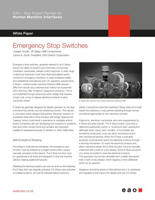
E-<strong>Stop</strong>s are critical to the human machine interface (HMI).<br />
restart. It should be noted that resetting E-<strong>Stop</strong>s does not in itself<br />
restart the machinery; it only permits restarting through normal<br />
procedures appropriate for the machinery involved.<br />
Ergonomic, electrical, mechanical, and color requirements for<br />
E-<strong>Stop</strong>s are quite specific. The E-<strong>Stop</strong> control, <strong>com</strong>monly a<br />
distinctive pushbutton switch or “mushroom type” pushbutton<br />
(although wires, ropes, bars, handles, or foot pedals are<br />
sometimes employed), must use direct mechanical action<br />
with mechanical latching. When the E-<strong>Stop</strong> is activated<br />
(pushed), it permanently opens the electrical contacts through<br />
a latching mechanism. To close the electrical contacts and<br />
allow machinery restart, the E-<strong>Stop</strong> actuator must be manually<br />
unlatched with a twist or a key release. Some E-<strong>Stop</strong> actuators<br />
can simply be pulled to close the electrical contacts.<br />
This approach may be less desirable from a safety standpoint<br />
than a twist or key release, which requires a more deliberate<br />
action by an operator.<br />
Designers should be aware of international and U.S. standards<br />
and regulations that impact the design and use of E-<strong>Stop</strong>s.
<strong>Emergency</strong> <strong>Stop</strong> <strong>Switches</strong> J. Torzillo, L. Scott<br />
Selecting the Right E-<strong>Stop</strong><br />
for Your Application<br />
Because of the confusing array of<br />
E-<strong>Stop</strong>s available, it is important to<br />
understand the design basics that<br />
contribute to high-quality, ergonomic<br />
switch design. EAO is a leader in HMI<br />
Components and Systems, including<br />
innovative, rugged, reliable, and<br />
affordable E-<strong>Stop</strong>s that meet or<br />
exceed international and U.S. standards.<br />
One of the first steps is determining<br />
where the E-<strong>Stop</strong> fits within your machine<br />
control system and whether your particular<br />
application requires Category 0 or Category<br />
1 type emergency shutdown. The intended<br />
application often determines the placement,<br />
size, electrical specifications, mechanical<br />
characteristics, ergonomics, color/legends,<br />
and number of E-<strong>Stop</strong>s required. So a<br />
thorough understanding of the machinery<br />
and associated control systems is key to<br />
making the right E-<strong>Stop</strong> choice.<br />
A second, and equally important step, is<br />
determining what international and U.S.<br />
standards, performance ratings, and codes<br />
apply for your application. Requirements<br />
vary by industry segment, so standards for<br />
E-<strong>Stop</strong>s used on transportation vehicles<br />
may differ significantly from those used on<br />
process machinery or medical equipment<br />
and will be governed by different regulatory<br />
bodies specific to those segments.<br />
Regulatory bodies may also specify size,<br />
color, legend, contact terminals, etc.<br />
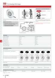
It is then useful to construct or consult<br />
an existing E-<strong>Stop</strong> series selector chart<br />
(often supplied by vendors). For example,<br />
EAO provides a chart that allows easy<br />
<strong>com</strong>parison of key design factors<br />
(see Figure 2). You can select panel<br />
An E-<strong>Stop</strong> must be initiated by a single human action using a manual control device.<br />
opening size, type of actuator, type and<br />
number of contact blocks, connectors,<br />
colors, and maximum electrical rating to<br />
<strong>com</strong>e up with one or more appropriate<br />
models.<br />
Like many vendors, EAO provides special<br />
enclosures, switch guards, palm guards,<br />
custom labeling, and other accessories to<br />
<strong>com</strong>plete virtually any E-<strong>Stop</strong> application.<br />
Some accessories may be specified by<br />
industry standards, such as the SEMI<br />
standards for semiconductor fabrication<br />
equipment that mandate the use of palm<br />
guards. EAO and other vendors also offer<br />
services to assist customers in the design,<br />
engineering, and production of HMI<br />
Systems, integrating E-<strong>Stop</strong>s.<br />
Designed for rough duty<br />
Robust, heavy-duty construction is the<br />
hallmark of the original 22.5 mm switches.<br />
Many, like the EAO Series 04 E-<strong>Stop</strong>s,<br />
have stackable contact blocks, optional<br />
key release actuators, and mounting<br />
options for 22.5 mm panel openings. This<br />
EAO series is rated at up to 10 A, 600<br />
VAC, has silver contacts with available<br />
gold over silver or silver over palladium<br />
contacts, and silver-plated screw terminals<br />
with available quick-connect terminals.<br />
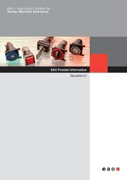
A 22.5 mm switch must be durable and rugged.<br />
Smaller mounting footprint<br />
Modern applications often demand<br />
a slimmed down E-<strong>Stop</strong> with 16 mm<br />
mounting. Innovative products, like the<br />
EAO Series 61, are now available with an<br />
actuator shape that prevents blockage<br />
from foreign objects, a black indicator<br />
ring visible from long distances, and<br />
available key release actuators. This EAO<br />
series is rated at 5 A, 250 VAC, and has a<br />
choice of silver or gold contacts, screw or<br />
solder quick-connect terminals.<br />
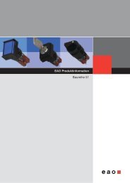
Today’s applications often require a slimmer footprint.<br />
2/8
<strong>Emergency</strong> <strong>Stop</strong> <strong>Switches</strong> J. Torzillo, L. Scott<br />
Figure 1 – Parts of an E-<strong>Stop</strong><br />
1<br />
2<br />
3<br />
4<br />
5<br />
EMERGENCY-STOP<br />
PUSHBUTTON ACTUATOR<br />
Actuators should be precision molded from<br />
high quality polymeric materials to assure a<br />
mechanical life in excess of 6,050 operations<br />
as required by industry standards, including<br />
EN IEC 60947 5-5, paragraph 7.3.3. In<br />
real life, E-<strong>Stop</strong>s generally exceed 250,000<br />
operations. Actuators can be “teaseproof,”<br />
twist-to-release, and foolproof in<br />
design. Actuators can also be pushbutton,<br />
mushroom, or key release.<br />
SEALING<br />
Many E-<strong>Stop</strong>s are sealed to IP 65 oil and<br />
watertight standards.<br />
FRONT PLATE<br />
Front plates can be designed to conform<br />
to color and legend standards.<br />
FIXING NUT<br />
E-<strong>Stop</strong>s have a variety of mounting<br />
options, for use in 22.5 mm or 16 mm<br />
panel openings.<br />
SWITCHING ELEMENT<br />
E-<strong>Stop</strong>s typically offer a range of contact<br />
options including gold over silver or silver<br />
over palladium, and silver-plated screw<br />
terminals with available quick-connect<br />
terminals.<br />
3/8
<strong>Emergency</strong> <strong>Stop</strong> <strong>Switches</strong> J. Torzillo, L. Scott<br />
Short behind-panel depth<br />
Newer electronic applications are<br />
requiring E-<strong>Stop</strong>s with shorter behindpanel<br />
depth. EAO’s Series 84 E-<strong>Stop</strong>,<br />
for example, features a very short behindpanel<br />
depth (18 mm maximum), single<br />
“mono-block” construction, 22.5 mm<br />
mounting, and available LED illumination<br />
that is visible from the side as well as<br />
front of the actuator. This series is rated<br />
at 3 A, 120 VAC and 1.5 A, 240 VAC,<br />
has gold contacts, quick-connect/solder<br />
printed circuit board terminals, and ribbon<br />
cable terminals.<br />
E-<strong>Stop</strong>s may require shorter behind-panel depth.<br />
Applications<br />
Virtually all industry segments – from<br />
machinery, instrumentation, medical<br />
treatment and diagnostic, lifting/<br />
moving, and transportation – mandate<br />
E-<strong>Stop</strong>s for safe operation. Designers<br />
need to have a thorough knowledge of<br />
E-<strong>Stop</strong> fundamentals, E-<strong>Stop</strong> switch<br />
characteristics and capabilities, and the<br />
international and U.S. standards and<br />
<strong>com</strong>pliance requirements that apply to<br />
their application areas.<br />
E-<strong>Stop</strong>s are required on all machinery<br />
independent of the type of energy used<br />
to control the function, except for machines<br />
in which an E-<strong>Stop</strong> function would<br />
not lessen the risk. An E-<strong>Stop</strong> switch is<br />
intended to be one part of a <strong>com</strong>prehensive<br />
safety system, so the equipment<br />
designer must also consider safety<br />
functions, such as reversal or limitation<br />
of motion, deflection, shielding, braking,<br />
or disconnecting, that are not specifically<br />
addressed in this paper. Primary application<br />
areas where electrical machinery<br />
is safeguarded with E-<strong>Stop</strong> technology<br />
include:<br />
Metalworking<br />
Wood production<br />
Textile production<br />
Food processing<br />
Printing<br />
Medical laser & x-ray equipment<br />
Packaging equipment<br />
Semi-fab equipment<br />
Pumping<br />
Lifting/moving equipment<br />
Plastics & rubber processing<br />
Materials handling<br />
Electronic production equipment<br />
Paper & cardboard production<br />
Inspection/testing equipment<br />
Compressors<br />
Laundry/dry cleaning facilities<br />
Transportation<br />
Construction/building materials<br />
X-ray Equipment<br />
Cabinet x-ray systems used for<br />
diagnostic and therapeutic medical<br />
applications, industrial non-destructive<br />
inspection and thickness gauging,<br />
security inspection of baggage, and<br />
other imaging are closely regulated for<br />
operational safety. E-<strong>Stop</strong>s are covered<br />
by standards and regulations of the<br />
FDA Department of Health and Human<br />
Services. The key document is CFR Title<br />
21, Part 1020 – Performance Standards<br />
for Ionizing Radiation Emitting Products,<br />
section 40, which requires accessible<br />
emergency stop switches and keyed<br />
lock-out switches to disable the system.<br />
Medical imaging E-<strong>Stop</strong>s are closely regulated.<br />
Semiconductor Manufacturing<br />
Semiconductor chips used in electrical<br />
and electronic devices are fabricated<br />
through a sequence of photographic<br />
and chemical processing steps. The<br />
process includes lithography, steppers,<br />
etching, and deposition equipment. The<br />
<strong>com</strong>plex process is governed by specific<br />
operational and safety guidelines set<br />
down by SEMI, a trade organization of<br />
suppliers of equipment and materials<br />
used in the fabrication of semiconductor<br />
devices. SEMI S2-93 makes a clear<br />
distinction between emergency off (EMO)<br />
switches and E-<strong>Stop</strong>s, requiring the latter<br />
to be clearly distinguishable from EMOs<br />
through the use of color (red), actuator<br />
shape (extended not mushroom), and<br />
labeling (“<strong>Emergency</strong> <strong>Stop</strong>”). It also<br />
specifies that E-<strong>Stop</strong>s should stop all<br />
hazardous mechanical motion at the<br />
equipment interface, but not shut off<br />
In semiconductor manufacturing, there are strict<br />
guidelines set by the SEMI trade organization.<br />
4/8
<strong>Emergency</strong> <strong>Stop</strong> <strong>Switches</strong> J. Torzillo, L. Scott<br />
associated equipment.<br />
Overhead and Gantry Cranes<br />
These large lifting and moving devices<br />
may have a gantry mounted cab which<br />
includes an E-<strong>Stop</strong> on the operator<br />
console. Smaller overhead cranes<br />
usually have a wired or wireless pendant<br />
control operated from ground level. The<br />
pendant includes an E-<strong>Stop</strong>. The chief<br />
regulating body for these massive devices<br />
is the Occupational Safety and Health<br />
Administration. OSHA 29 CFR 1910.179<br />
(a)(59) defines “emergency stop switch”<br />
as a manually or automatically operated<br />
electric switch to cut off electric power<br />
independent of the regular operating<br />
controls. Another section, 9 CFR<br />
1910.179(a)(61) defines “main switch”<br />
E-<strong>Stop</strong>s can be mounted on a console or on a<br />
wireless pendant.<br />
as a device controlling the entire power<br />
supply to the crane.<br />
U.S. Standards for E-<strong>Stop</strong>s<br />
Occupational Safety and Health<br />
Administration (OSHA) – Standards –<br />
29 CFR (Code of Federal Regulations);<br />
OSHA 1910<br />
American National Standards Institute<br />
(ANSI) – B11, Electrical and Mechanical<br />
Equipment Guidelines<br />
ANSI/NFPA (National Fire Protection<br />
Association) – 79, Electrical Standards<br />
for Industrial Machinery<br />
Underwriters Laboratories Inc. (UL) –<br />
Category NISD, <strong>Emergency</strong> <strong>Stop</strong> Device<br />
Food and Drug Administration,<br />
Department of Health and Human<br />
Services, Subchapter J – Radiological<br />
Health: CRF Title 21, Part 1020,<br />
Performance Standards for Ionizing<br />
Radiation Emitting Products<br />
Other Compliance<br />
and Rating Bodies<br />
Most quality E-<strong>Stop</strong> switches, including<br />
those made by EAO, are RoHS and<br />
REACH <strong>com</strong>pliant, meet cUL (Canadian<br />
UL) requirements, and TÜV (Technischer<br />
Überwachungsverein, a German safety<br />
monitoring agency), SEV (a Swiss<br />
designation) and CE (European Union)<br />
approvals.<br />
Depending on design and application<br />
requirements, many E-<strong>Stop</strong>s are listed<br />
as UL category NISD emergency<br />
stop devices. This rating covers two<br />
categories of E-<strong>Stop</strong> function as defined<br />
in ANSI/NFPA 79, Electrical Standards<br />
for Industrial Machinery (ANSI is the<br />
American National Standards Institute<br />
and NFPA is the National Fire Protection<br />
Association):<br />
1. <strong>Stop</strong> Category 0 – Immediate removal<br />
of power to the machine or mechanical<br />
disconnection (de-clutching) of hazardous<br />
elements.<br />
2. <strong>Stop</strong> Category 1 – Controlled stop<br />
with power available to stop the machine<br />
followed by removal of power when the<br />
stop is achieved.<br />
The emergency stop actuator provided<br />
in these devices must be a self-latching<br />
type. E-<strong>Stop</strong>s with this rating have been<br />
reviewed for their functionality in addition<br />
to fire and electric shock safety.<br />
Figure 2 - Key Design Factors<br />
22.5 mm panel opening<br />
16 mm panel opening<br />
ISO 13850 (formerly EN418)<br />
“Tease-Proof” actuator<br />
Stackable contact blocks/elements<br />
Short “behind-panel” depth<br />
(18 mm max)<br />
Illumination<br />
Cap color other than red<br />
Screw terminals<br />
Quick-connect/solder terminals<br />
Ribbon cable terminals<br />
Sealed to IP 65 oil and watertight<br />
standards<br />
Twist-to-release actuator<br />
Key-release actuator<br />
Enclosure<br />
Legend plates<br />
Protective shroud<br />
Max rating: 10 A/600 VAC<br />
Max rating: 10 A/660 VAC<br />
Max rating: 5 A/250 VAC<br />
Max rating: 3 A/250 VAC<br />
5/8
<strong>Emergency</strong> <strong>Stop</strong> <strong>Switches</strong> J. Torzillo, L. Scott<br />
Figure 3 – International standards that apply to <strong>Emergency</strong> <strong>Stop</strong>s vs. <strong>Stop</strong> <strong>Switches</strong><br />
General<br />
Color of actuator Actuators of emergency switching off devices shall be colored RED.<br />
• EN IEC 60947-5-5 § 4.2.1 • EN 60204-1 § 10.8.3 • DIN EN ISO 13850 § 4.4.5<br />
Actuator/Background When a background exists behind the actuator, and as far as it is practicable,<br />
it shall be colored yellow.<br />
• EN IEC 60947-5-5, 4.2.1 • EN 60204-1, 10.8.3 • DIN EN ISO 13850 § 4.4.5<br />
Inscription of actuator The direction of unlatching shall be clearly identified when resetting<br />
is achieved by rotation of the button.<br />
• EN IEC 60947-5-5 § 4.2.1<br />
Electrical requirements<br />
Utilization categories The utilization categories shall be AC-15 and/or DC-13 and/or DC-14 in accordance<br />
with EN 60947-5-1.<br />
• EN IEC 60947-5-5 § 5.1<br />
Direct opening action All normally closed contact elements of an emergency stop device shall have<br />
a direct opening action (positive opening action).<br />
• EN IEC 60947-5-5 § 5.2<br />
Latching It shall not be possible for the emergency stop device to latch-in without<br />
generating the emergency stop signal.<br />
• EN IEC 60947-5-5 § 6.2.1<br />
Resetting Resetting of the emergency stop shall only be possible as the result of a manual<br />
action at the location where the emergency stop was initiated.<br />
• EN ISO 13850, 4.4.4<br />
Resetting The resetting of the latching means shall be by turning a key, by rotation of the<br />
button in the designated direction, or by a pulling motion.<br />
• EN IEC 60947-5-5 § 6.3.1<br />
Testing<br />
Robustness of A button actuator shall withstand a torque as specified below, in both directions of latched<br />
a button activator actuator and unlatched positions, where the resetting action requires rotation of the push-button.<br />
• EN IEC 60947-5-5 § 7.3.2 Ø Force Torque<br />
16 mm 80 N 1.6 Nm<br />
22 mm 110 N 2.2 Nm<br />
30 mm 150 N 3.0 Nm<br />
Durability test The test shall consist of 6,050 cycles in which latching and resetting of the actuator occurs<br />
during each cycle.The movement and actuating forces shall be consistent throughout the<br />
test. Monitoring of these parameters shall be carried out to ensure consistency.<br />
• EN IEC 60947-5-5 § 7.3.3<br />
Norms<br />
<strong>Emergency</strong> <strong>Stop</strong> <strong>Stop</strong> Switch<br />
Mandatory standards • EN IEC60947-5-5 (International Standard) • EN ISO 13850 (Safety of Machinery)<br />
• EN 60204-1 (Safety of Machinery)<br />
Not defined<br />
Not defined<br />
Not defined<br />
Not defined<br />
Not necessary<br />
Not defined<br />
Not defined<br />
Not defined, but usually realized by turning<br />
a key, by rotation of the button in the<br />
designated direction, or by a pulling motion.<br />
Not defined<br />
Not defined<br />
Not defined<br />
6/8
<strong>Emergency</strong> <strong>Stop</strong> <strong>Switches</strong> J. Torzillo, L. Scott<br />
Future of the Technology<br />
The pace of change in E-<strong>Stop</strong><br />
technology is steady, not revolutionary.<br />
By their nature, these devices must<br />
be recognizable, reliable, and rugged.<br />
They have a straightforward function:<br />
instantly shut down equipment with<br />
a simple push of a (usually) bright red<br />
actuator. For safety, reactivation of the<br />
switch requires twisting or pulling the<br />
actuator by hand or, for even more<br />
security, unlocking it with a key before<br />
machinery can be restarted. Established<br />
standards, function, and familiarity dictate<br />
a certain beneficial inertia in new E-<strong>Stop</strong><br />
developments.<br />
Many advances are driven by norm<br />
changes for E-<strong>Stop</strong>s, such as DIN EN<br />
ISO 13850: 2008 that now requires<br />
mechanical latching and manual<br />
resetting of E-<strong>Stop</strong>s. Most research<br />
and development is aimed at improving<br />
the safety and reliability of the switches<br />
themselves and expanding their roles as<br />
lockout devices in some worker safety<br />
applications.<br />
One area of current interest is making<br />
sure that the E-<strong>Stop</strong> itself will “failsafe”<br />
should the actuator and contact block<br />
be separated. The contact block has<br />
normally closed contacts that allow<br />
Once you understand the E-<strong>Stop</strong> function and relevant standards, codes, and <strong>com</strong>pliances you can<br />
determine the appropriate device.<br />
power to flow to the machinery. Pushing<br />
an E-<strong>Stop</strong> separates the spring-loaded<br />
contacts, and mechanical latching keeps<br />
them open, stopping the machinery. But<br />
what happens if the actuator separates<br />
from the contact block or the latching<br />
mechanism fails?<br />
Separation of the contact block from the<br />
actuator renders an E-<strong>Stop</strong> ineffective.<br />
Current solutions include mono-block<br />
or unibody switches with a one-piece<br />
actuator/contact block, as well as<br />
switches with failsafe contact blocks that<br />
automatically cause machinery shutdown<br />
if the actuator and contact block are<br />
separated.<br />
Other advances are application-driven.<br />
EAO’s Series 84 E-<strong>Stop</strong>s, for example,<br />
were developed for hand-held enclosures<br />
with slim behind-panel depth for robotics<br />
applications. These versatile E-<strong>Stop</strong>s<br />
also are used in pendant controls for<br />
lifting and moving machinery. Application<br />
requirements have also created a wide<br />
variety of available optional features and<br />
accessories for most E-<strong>Stop</strong> products –<br />
illumination, protective rings, enclosures,<br />
guards, legend plates, etc. – that add<br />
to the functionality and safety of E-<strong>Stop</strong><br />
installations.<br />
E-<strong>Stop</strong>s will continue to evolve to meet<br />
new standards and new applications.<br />
For designers, the most important<br />
considerations in making the right design<br />
decisions are a thorough understanding<br />
of E-<strong>Stop</strong> function; a grounding in the<br />
standards, codes, and <strong>com</strong>pliances<br />
involved; proper selection of devices<br />
that meet or exceed the application<br />
requirements.<br />
7/8
<strong>Emergency</strong> <strong>Stop</strong> <strong>Switches</strong> J. Torzillo, L. Scott<br />
EAO Ltd<br />
Highland House<br />
Albert Drive, Burgess Hill<br />
West Sussex, RH15 9TN<br />
Tel: 01444 236000<br />
E-mail: sales.euk@eao.<strong>com</strong><br />
www.eao.co.uk<br />
Member of the EAO Group