A System for Automated Fixture Planning with Modular Fixtures
A System for Automated Fixture Planning with Modular Fixtures
A System for Automated Fixture Planning with Modular Fixtures

You also want an ePaper? Increase the reach of your titles
YUMPU automatically turns print PDFs into web optimized ePapers that Google loves.
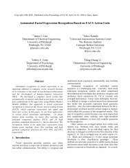
3.2. Interference Checking<br />
16<br />
The location of every fixture component in a fixtllre plan should be determined so that they do not<br />
interfere <strong>with</strong> part geometry, cum paths, and odw fixture compa0entF. Currently, when determining the<br />
location of a fixture component, a tool designer relies on visual inspection to duect any interference. Since<br />
swept volumes of cutter paths are not explicitly displayed on a typical CAD-based fixtllre planning system,<br />
the visual inspection of the tool designer is imprecise in nature; behhe tends m determine the location of<br />
fixture components futher away from any cutter paths than necessary in order to avoid any interference<br />
<strong>with</strong> cutter paths. A precise analytic tool <strong>for</strong> inrerference checking would not only speed up the process,<br />
but also help demmh !matbn%.of fLm compcnents <strong>with</strong>oat h g . too consa~ave even under<br />
complex cutting operarioas.<br />
F’art geometry and future components’ geomeay can be explicitly stored in a data- and displayed on a<br />
graphics terminal. Ihe swept volume of a cutter path can be cooshucted in the spce as a polyhedral object<br />
using the cutter’s diameter and the cutter path specified in the, pan coordioares. The details used m<br />
consrmcf the swept volumes will be disc& in chapter 4.<br />
Although algarithms exist which detect interference between LWO objects in space, tbese algorithms ax<br />
computationally intensiva Ihm, the possibility of interference seeds to be checked first by simpler<br />
schemes m speea up the analysis. One simple sheme is to check interfenacc by comparing the minimal<br />
and maximal x, y, and z cmxdmam . of two objects dcsaibad Wim respect to an arbitrary Cartesian<br />
A A A A A A<br />
coordinate system. Let &, y-. k, &, y-, and & be the minimal and maximal x, y, z<br />
coordinates of an ob* k Also, let L, yk, &, Cu, yL be the minimai and maximal x. y, z<br />
coordinates of an object B. Then, if any of the following sufficiear mndirioas are Wed. there is no<br />
interference between objects A and B<br />
A B<br />
when x- > x,,,~, or<br />
A B<br />
when y- > ymu. or<br />
A B<br />
when > q-, or<br />
A B<br />
when xnux < h, or<br />
A B<br />
when ym < y-, or<br />
A B<br />
when m, < L.<br />
Figure 3-1 shows three objects in the Carresian coordinate system (For brevity, only x and y coordinates<br />
are shown in 2D). While. the mordiaate cMnplnison ~eognizes that objects (A and B) and (A and C) do<br />
not interfere at ail, it detects the pospibility of imaferenm between objects B and C. Thns, an intersection<br />
checking algorithm should be used to refine the wwez at &is point<br />
Another simple scheme to check the possibility of interference between two objects is to bound each<br />
object by a sphere oracylinderand check the sum of two radii and the distance between sphere centers<br />
(Figure 3-2) [Kim 851.