A System for Automated Fixture Planning with Modular Fixtures
A System for Automated Fixture Planning with Modular Fixtures
A System for Automated Fixture Planning with Modular Fixtures

You also want an ePaper? Increase the reach of your titles
YUMPU automatically turns print PDFs into web optimized ePapers that Google loves.
30<br />
In a future plan <strong>with</strong> overhead clamps, each clamp is assumed to apply the Same amount of damping<br />
<strong>for</strong>ce. The minimized due of the objective function is the necessary clamping <strong>for</strong>ce. In a fixture pIm<br />
<strong>with</strong> a vise. the necessary clamping <strong>for</strong>ce <strong>for</strong> a movable jaw is 3 times the clamping <strong>for</strong>ce at a point contact.<br />
If the magnitude of the clamping <strong>for</strong>ce at the active contact is <strong>with</strong>in the maximal clamping <strong>for</strong>ce of a<br />
clamp (or vise), the fixme plan is valid. ?he least required clamping <strong>for</strong>ce to hold the prt rigidly during<br />
machining is the largest clamping <strong>for</strong>ce among the least clamping <strong>for</strong>ces necessary to maintain the part’s<br />
equilibrium <strong>for</strong> each cutting <strong>for</strong>ce.<br />
3.4.3. Remarks<br />
Force analysis is computationally expensive, and it is not possible to considex evay <strong>for</strong>ce direction along<br />
each cutm path. Often, a mup may inciude multiple feaMes to cut In order to estimate the clamping<br />
<strong>for</strong>ce <strong>with</strong> the milling operaiions, various directions of culling <strong>for</strong>ces may be considered. Thus. a few<br />
represenmtive <strong>for</strong>ce directions at each milling cuter path can be used to speed up the computation.<br />
3.5. Checking part deflection<br />
Part deflection during machining can deteriome part accuracy and cause dynamic problems such as<br />
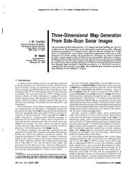
chatters in the cutting tod and vibrations in a padfixture assembly, a. Far example, when drilling a hole<br />
in il poorly-supported thin part, severe part deflection not only causes the prt to vibrate, but also may break<br />
the drill (see figure 3-11).<br />
support<br />
Figure 3-11: Part detktion due to driUig<br />
When a candidate fixture plan is mth the damping <strong>for</strong>ce at every clamping cornpent, it IS<br />
necessary m check whether pan deflection due to dampmg <strong>for</strong>ce or cutting <strong>for</strong>ce s acceptable. The sues<br />
applied on the contact area between the clamp and the part c, can be estrmated by<br />
F<br />
Q- A<br />
where F is the clamping <strong>for</strong>ce and A is the contact area been the clamp and the pan For example, let<br />
us assume that a swing clamp driven by hydraulic power can apply up to l0,OOO lbs <strong>for</strong>ce. If the contact