Design of Outfit Elements in Ships for Fatigue Technical ... - EWF
Design of Outfit Elements in Ships for Fatigue Technical ... - EWF
Design of Outfit Elements in Ships for Fatigue Technical ... - EWF

Create successful ePaper yourself
Turn your PDF publications into a flip-book with our unique Google optimized e-Paper software.
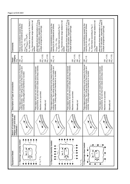
Page 2 <strong>of</strong> DVS 3501<br />
Comments<br />
Description <strong>of</strong> Type <strong>of</strong> connection Detail<br />
category<br />
∆σR Equipment Detail Sketch <strong>of</strong> connection with<br />
fatigue crack and stress<br />
considered σ<br />
Stress concentrations caused by the<br />
open<strong>in</strong>g to be considered as follows<br />
140<br />
(m0 = 4)<br />
Plate edges punched or mach<strong>in</strong>e-cut by means <strong>of</strong> a thermal<br />
cutt<strong>in</strong>g process. The cutt<strong>in</strong>g surface is free <strong>of</strong> cracks and<br />
notches. Cutt<strong>in</strong>g edges are chamfered or rounded<br />
1.1 Open<strong>in</strong>gs uniaxially loaded<br />
∆σmax = K1 ⋅ ∆σN bzw. ∆σRperm ≤ ∆σR /K t<br />
K t: Notch factor accord<strong>in</strong>g to GL Section 3<br />
∆σN: Nom<strong>in</strong>al stress range related to net<br />
section<br />
alternatively direct determ<strong>in</strong>ation <strong>of</strong> ∆σmax from FE-calculation, especially <strong>in</strong> case <strong>of</strong><br />
multiple arrangement <strong>of</strong> open<strong>in</strong>gs<br />
Plate edges which are not meet<strong>in</strong>g the above mentioned<br />
requirements, but are free from cracks and sharp notches<br />
125<br />
(m0 = 3.5)<br />
Mach<strong>in</strong>e cut or punched:<br />
or σ x >> σ y<br />
100<br />
(m0 = 3.5)<br />
Manually cut:<br />
Stress concentrations caused by the<br />
open<strong>in</strong>g to be considered as follows<br />
140<br />
(m0 = 4)<br />
Plate edges punched or mach<strong>in</strong>e-cut by means <strong>of</strong> a thermal<br />
cutt<strong>in</strong>g process. The cutt<strong>in</strong>g surface is free <strong>of</strong> cracks and<br />
notches. Cutt<strong>in</strong>g edges are chamferred or rounded<br />
1.2 Open<strong>in</strong>gs biaxially loaded<br />
∆σmax = K1 ⋅ ∆σN K t: Notch factor accord<strong>in</strong>g to Fig. 2<br />
∆σN : Nom<strong>in</strong>al stress range related to net<br />
section<br />
alternatively direct determ<strong>in</strong>ation <strong>of</strong> ∆σmax from FE-calculation, especially <strong>in</strong> case <strong>of</strong><br />
multiple arrangement <strong>of</strong> open<strong>in</strong>gs<br />
Plate edges which are not meet<strong>in</strong>g the above mentioned<br />
requirements, but are free from cracks and sharp notches<br />
125<br />
(m0 = 3.5)<br />
Mach<strong>in</strong>e cut or punched:<br />
100<br />
(m0 = 3.5)<br />
Manually cut:<br />
σ x ≈ σ y<br />
Stress concentrations caused by the<br />
open<strong>in</strong>g to be considered as follows<br />
140<br />
(m0 = 4)<br />
1.3 Open<strong>in</strong>gs shear-loaded Plate edges punched or mach<strong>in</strong>e-cut by means <strong>of</strong> a thermal<br />
cutt<strong>in</strong>g process. The cutt<strong>in</strong>g surface is free <strong>of</strong> cracks and<br />
notches. Cutt<strong>in</strong>g edges are chamferred or rounded<br />
∆σmax = K1 ⋅ ∆σN K t: Notch factor accord<strong>in</strong>g to Fig. 3<br />
∆σN : Nom<strong>in</strong>al stress range related to net<br />
section<br />
alternatively direct determ<strong>in</strong>ation <strong>of</strong> ∆σmax from FE-calculation, especially <strong>in</strong> case <strong>of</strong><br />
multiple arrangement <strong>of</strong> open<strong>in</strong>gs<br />
Plate edges which are not meet<strong>in</strong>g the above mentioned<br />
requirements, but are free from cracks and sharp notches<br />
125<br />
(m0 = 3.5)<br />
Mach<strong>in</strong>e cut or punched:<br />
100<br />
(m0 = 3.5)<br />
Manually cut: