Utility Digital Plan Submittal Requirements - City of North Las Vegas
Utility Digital Plan Submittal Requirements - City of North Las Vegas
Utility Digital Plan Submittal Requirements - City of North Las Vegas

Create successful ePaper yourself
Turn your PDF publications into a flip-book with our unique Google optimized e-Paper software.
Mayor<br />
Michael L. Montandon<br />
Council Members<br />
William E. Robinson<br />
Stephanie S. Smith<br />
Shari Buck<br />
Robert L. Eliason<br />
<strong>City</strong> Manager<br />
Gregory E. Rose<br />
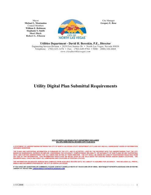
Utilities Department - David H. Bereskin, P.E., Director<br />
Engineering Services Division • 2829 Fort Sumter Dr • <strong>North</strong> <strong>Las</strong> <strong>Vegas</strong>, Nevada 89030<br />
Telephone: (702) 633-1276 • Fax: (702) 649-9784 • TDD: (800) 326-6868<br />
www.city<strong>of</strong>northlasvegas.com<br />
<strong>Utility</strong> <strong>Digital</strong> <strong>Plan</strong> <strong>Submittal</strong> <strong>Requirements</strong><br />
CITY OF NORTH LAS VEGAS UTILITY DEPARTMENT DISCLAIMER<br />
GIS, GPS, RDMS DIGITAL OR HARD COPY PLAN DATA<br />
A STATEMENT OF UNDERSTANDING BETWEEN THE CITY OF NORTH LAS VEGAS UTILITY DEPARTMENT (CITY) AND ANY AND ALL SUBSEQUENT USERS OF INFORMATION<br />
OBTAINED HEREFROM:<br />
THE PLANS AND SUPPORTING INFORMATION IS FURNISHED BY THE CITY, AND IS ACCEPTED / USED BY THE RECIPIENT WITH THE UNDERSTANDING THAT THE CITY<br />
MAKES NO WARRANTIES, EXPRESS OR IMPLIED, CONCERNING THE ACCURACY, COMPLETENESS, RELIABILITY, OR SUITABILITY OF SAID PLANS OR ANY SUPPORTING<br />
DATA, AND FURTHER UNDERSTANDS THAT ALL USERS ARE ACTING AT THEIR OWN RISK. THE CITY SHALL BE UNDER NO LIABILITY WHATSOEVER RESULTING FROM<br />
ANY USE OF THIS INFORMATION. THIS INFORMATION SHOULD NOT BE RELIED UPON AS THE SOLE BASIS FOR EXISTING WATER AND/OR SEWER LOCATIONS. THE<br />
ENGINEER SHALL CHECK AND VERIFY ALL DIMENSIONS AND LOCATIONS OF EXISTING UTILITIES.<br />
R & SEWER FACILITIES<br />
THE INFORMATION DELINEATED HEREON WAS COMPILED FROM AVAILABLE RECORD DATA; NO LIABILITY IS ASSUMED FOR ACCURACY. THIS INCLUDES ALL PRINTS,<br />
EMAILS AND DOCUMENTS PROVIDED BY THE CITY OF NORTH LAS VEGAS.<br />
IF YOU HAVE ANY QUESTIONS OR COMMENTS, PLEASE CONTACT DANIELLE NEATH AT 702-633-2406 OR BY EMAIL: NEATHD@CITYOFNORTHLASVEGAS.COM OR WAYNE<br />
LINDSAY AT 702-633-1898, LINDSAYW@CITYOFNORTHLASVEGAS.COM.<br />
1/15/2008J:\Standards\NLV CAD STANDARDS\CNLV_Standards\Documents\CNLV Electronic <strong>Plan</strong> <strong>Requirements</strong>.doc 1
Utilities <strong>Digital</strong> <strong>Plan</strong> <strong>Submittal</strong> <strong>Requirements</strong><br />
RELEASE HISTORY<br />
Version Date Description<br />
1.0 May 01 2007 Original Document Release<br />
2.0 January 10, 2008 Clarification on Layering, Projections and Comprehensive<br />
<strong>Utility</strong> plan. Removed need for Hydraulic Network<br />
Analysis. Removed Appendix One. Added modified<br />
blocks. Included on line updated parcel file January 2008<br />
1/15/2008J:\Standards\NLV CAD STANDARDS\CNLV_Standards\Documents\CNLV Electronic <strong>Plan</strong> <strong>Requirements</strong>.doc 2
Mayor<br />
Michael L. Montandon<br />
Council Members<br />
William E. Robinson<br />
Stephanie S. Smith<br />
Shari Buck<br />
Robert L. Eliason<br />
<strong>City</strong> Manager<br />
Gregory E. Rose<br />
Utilities Department - David H. Bereskin, P.E., Director<br />
Engineering Services Division • 2829 Fort Sumter Dr • <strong>North</strong> <strong>Las</strong> <strong>Vegas</strong>, Nevada 89030<br />
Telephone: (702) 633-1276 • Fax: (702) 649-9784 • TDD: (800) 326-6868<br />
www.city<strong>of</strong>northlasvegas.com<br />
Utilities <strong>Digital</strong> <strong>Plan</strong> <strong>Submittal</strong> <strong>Requirements</strong><br />
Introduction: <strong>Digital</strong> Data Submission Standards<br />
The <strong>City</strong> <strong>of</strong> <strong>North</strong> <strong>Las</strong> <strong>Vegas</strong> has adopted geographical information system (GIS) technologies to store,<br />
manage, and maintain geographic / spatially-related data. Likewise, the majority <strong>of</strong> the civil engineering<br />
community has evolved to the point where the predominating design environment is computer-aided<br />
design and drafting (CAD). It is the goal <strong>of</strong> the <strong>City</strong> to use GIS and CAD technologies to expedite the<br />
design and review processes within the administration, by developing standards and procedures for<br />
integration <strong>of</strong> digital engineering CAD drawings into the GIS environment, maintaining the integrity and<br />
positional accuracy <strong>of</strong> the data.<br />
<strong>Digital</strong> data submittals are required for both the approved engineering / improvement plans and<br />
Hydraulic Network Analyses. The CNLV <strong>Digital</strong> <strong>Submittal</strong> Standards are based on the American<br />
National Standards Institute (ANSI).<br />
<strong>Digital</strong> submittals shall conform to the following:<br />
<strong>Digital</strong> <strong>Utility</strong> <strong>Plan</strong> <strong>Submittal</strong> Summary<br />
1) Include one comprehensive <strong>Utility</strong> plan in a *.dwg format in model space showing all proposed<br />
project utilities and all existing and proposed easements on one sheet including both on-sites and<br />
<strong>of</strong>f-sites.<br />
2) Ensure that the <strong>Utility</strong> <strong>Plan</strong> is inserted into the correct spatial location <strong>of</strong> the parcel data<br />
contained in Appendix Two (State <strong>Plan</strong>e Projection).<br />
A) The proposed comprehensive utility plan project needs to be moved and rotated to the<br />
street centerline or sectional corner coordinates that will generally geo-reference the<br />
consultant’s work and keep all distances in ground values.<br />
B) The <strong>City</strong> requires the POC <strong>of</strong> the proposed project to be based upon the <strong>City</strong>’s current<br />
GIS data for existing water and sewer data. This data is not required to be included in the<br />
digital submittal. The point <strong>of</strong> commencement <strong>of</strong> the proposed project needs to be<br />
clearly indicated in the digital submittal by the labeling <strong>of</strong> “POC”.<br />
C) Note that no other plans or paper space sheets in the proposed project are required to be<br />
moved to the State <strong>Plan</strong>e Projection other than the comprehensive utility plan.<br />
1/15/2008J:\Standards\NLV CAD STANDARDS\CNLV_Standards\Documents\CNLV Electronic <strong>Plan</strong> <strong>Requirements</strong>.doc 3
3) Water, Sewer, and Storm Drain layers in the AutoCAD drawing shall be per ANSI standards as<br />
indicated in Appendix One. Each layer shall clearly indicate the pipe size and/or the type <strong>of</strong><br />
appurtenance.<br />
4) Include a plan set layout (Key Map Overlay) <strong>of</strong> all <strong>Utility</strong> sheets in the encompassing project per<br />
Appendix Two, Figure 3.<br />
5) All proposed and existing easements and right-<strong>of</strong>-ways are to be included on their own<br />
individual AutoCAD layer. All documents and records <strong>of</strong> survey are required to be provided in a<br />
pdf format on the submittal CD.<br />
Note: The main purpose <strong>of</strong> this digital submittal project is that the Industry draws a pipeline or<br />
appurtenance once in the lifecycle <strong>of</strong> the project. The <strong>City</strong> intends to map all <strong>of</strong>f-site and on-site<br />
facilities. This data would then be available in a digital format to customers / clients, resulting in a more<br />
efficient and effective process / program for sharing digital data to the community.<br />
1/15/2008J:\Standards\NLV CAD STANDARDS\CNLV_Standards\Documents\CNLV Electronic <strong>Plan</strong> <strong>Requirements</strong>.doc 4
Electronic <strong>Plan</strong> <strong>Requirements</strong><br />
Since March 1, 2005, the Utilities Department has required a Compact Disk containing electronic<br />
drawing files when submitting approved engineering / improvement plans on mylars. No Mylar Project<br />
will be approved without a correct digital submittal.<br />
The “Approved Engineering / Improvement <strong>Plan</strong>” (Mylar) submittals shall include an electronic copy on<br />
Compact Disk (CD) or (DVD). This submittal shall include three parts:<br />
1) A folder named “Improvement <strong>Plan</strong>s” containing the approved engineering / improvement plan<br />
set. This may be submitted in bound XRef form (*.dwg, see file naming section below), *.pdf or<br />
*.dwf.<br />
2) A folder named “<strong>Utility</strong> GIS <strong>Submittal</strong>” containing the overall comprehensive utility plan as laid<br />
out in these standards.<br />
3) A folder named “Hydraulic Analysis” containing either the Hydraulic Analysis Files or the<br />
aforementioned “Hydraulic Analysis Not Required” text file.<br />
<strong>Utility</strong>, Model Space Drawing<br />
One encompassing Model Space <strong>Plan</strong> <strong>of</strong> the approved / improvement project shall be submitted in one<br />
encompassing model space drawing file. This file shall include all proposed <strong>of</strong>f-site and on-site utilities.<br />
This file shall be spatially oriented within the downloadable parcel template available from the <strong>City</strong>’s<br />
website: http://www.city<strong>of</strong>northlasvegas.com/Departments/Utilities/UtilitiesEngineering.shtm.<br />
Key Map Overlay<br />
A Model Space Key Map Overlay shall show the individual plan <strong>of</strong> each geo-referenced individual plan<br />
sheet extents. This overlay should correspond precisely with any matchline in your sheet set. See<br />
Figure 3 and Figure 4. The layers are provided in the CNLV <strong>Digital</strong> <strong>Submittal</strong> Template.<br />
Project Setup<br />
It is a requirement that the <strong>Utility</strong> <strong>Plan</strong> is inserted into the correct spatial location <strong>of</strong> the parcel data<br />
contained in Appendix Two (State <strong>Plan</strong>e Projection).<br />
1) The proposed comprehensive utility plan project needs to be moved and rotated to the street<br />
centerline or sectional corner coordinates that will generally geo-reference the consultant’s work<br />
and keep all distances in ground values.<br />
2) The <strong>City</strong> requires the POC <strong>of</strong> the proposed project to be based upon the <strong>City</strong>’s current GIS data<br />
for existing water and sewer data. This data is not required to be included in the digital<br />
submittal. The point <strong>of</strong> commencement <strong>of</strong> the proposed project needs to be clearly indicated in<br />
the digital submittal by the labeling <strong>of</strong> “POC”.<br />
3) Note that no other plans or paper space sheets in the proposed project are required to be moved<br />
to the State <strong>Plan</strong>e Projection other than the comprehensive utility plan.<br />
1/15/2008J:\Standards\NLV CAD STANDARDS\CNLV_Standards\Documents\CNLV Electronic <strong>Plan</strong> <strong>Requirements</strong>.doc 5
4) Model Space – The drawing must be drawn in at full scale (1:1). Units are to be set to Decimal<br />
Feet at precision factor 0.00. Angle units are to be set to Decimal Degrees at precision factor<br />
0.00. Insertion units for blocks and Xrefs are to be set to Feet.<br />
5) Standard Sheet Sizes and Formats – All sheet sizes are to be ARCH D Plot – 24” x 36”<br />
(preferred format).<br />
6) Standard Symbols / Blocks – Standard Symbols shall be used to reduce drafting time, increase<br />
legibility and conserve space. Symbols must be consistent throughout the plan set in accordance<br />
with <strong>City</strong> <strong>of</strong> <strong>North</strong> <strong>Las</strong> <strong>Vegas</strong> standards as outlined in the schedules. All blocks shown are<br />
standard AutoDesk type blocks (provided by the <strong>City</strong> <strong>of</strong> <strong>North</strong> <strong>Las</strong> <strong>Vegas</strong> Utilities Department).<br />
If a block is not present, then a renamed copy <strong>of</strong> a provided block is acceptable. All created<br />
blocks needs to have a 0.0 insertion point and created on layer 0.<br />
7) Layering:<br />
A) Layer names for required layers must appear exactly as in Appendix Table 1. The base<br />
layers are provided in the CNLV Standards File(s).<br />
B) All required layers listed in the CAD layers must contain only the features that are<br />
described for that layer. For example, the B-BNDY-CNLV layer must only contain the<br />
boundary line and not such features as north arrows or parcels.<br />
C) All required layers must be present in the drawing except for features that do not pertain<br />
to a particular project. For example, some commercial projects or apartment complexes<br />
may not contain sewer taps as part <strong>of</strong> the construction and should not be included in the<br />
drawing.<br />
D) All layers must be clearly differentiated from each other.<br />
i) Two layers having the names “C-WATR-PIPE-XXXX” and “C-WATR-PIPES-<br />
XXXX” should not exist in the same drawing.<br />
ii) C-SEWR-PIPE-XXXX and SEWER-PIPE should not exist in the same drawing.<br />
iii) C-SEWR-PIPE-0006 and C-SEWR-PIPE-0010 is preferred.<br />
iv) All text must appear on separate layers from the layers they annotate. For<br />
example, text describing a sewer line must be on the C-SEWR-ANNO layer, not<br />
the C-SEWR-PIPE-XXXX layer, or any other layer in the drawing. Map<br />
annotation templates are acceptable.<br />
v) Text leaders should be placed on the text layer, not the feature layer. For<br />
example, the leader for the diameter <strong>of</strong> a water pipe should be on the C-WATR-<br />
ANNO layer, not the C-WATR-PIPE-XXXX layer.<br />
vi) Every individual feature class should be differentiated. Each pipe size should be<br />
differentiated and each appurtenance type should be differentiated [i.e. 6” Water<br />
Pipe is C-WATR-PIPE-0006 and 12” Water Pipe is C-WATR-PIPE-0012]. The<br />
XXXX is a user defined field and should be used to further define and<br />
differentiate items.<br />
1/15/2008J:\Standards\NLV CAD STANDARDS\CNLV_Standards\Documents\CNLV Electronic <strong>Plan</strong> <strong>Requirements</strong>.doc 6
The <strong>City</strong> will provide to any Engineering consultant, upon a customer request (see form on website), a<br />
full digital file <strong>of</strong> all water and sewer data for the extents <strong>of</strong> that project. However, the <strong>City</strong> will not<br />
provide a drawing <strong>of</strong> the complete <strong>City</strong> network.<br />
Drawing Principles<br />
1) All layers must conform to the aforementioned layer standards.<br />
2) All Polygon type features must be completely closed. Lines may need to be duplicated on more<br />
than one layer.<br />
A) Subdivision / project parcels must be to closed figures on their layer (not closed with the<br />
subdivision / project boundary).<br />
B) Road edge-<strong>of</strong>-pavement and road right-<strong>of</strong>-way must be drawn as closed polygons.<br />
C) Where a polygon feature extends beyond the edge <strong>of</strong> the plan, the property boundary<br />
(repeated on the polygon feature’s layer) will be used to close the polygon.<br />
D) All edges on polygon features must be snapped together at the vertices. Gaps in polygon<br />
boundaries will not be accepted.<br />
3) Sewer Features:<br />
A) Sewer Lines and Sewer Taps need to be digitized with proper directionality: Lines must<br />
be drawn from the uphill node to the downhill node or flipped after the lines have been<br />
digitized.<br />
B) All tangents between sewer manholes need to be drawn with a single polyline. Lines<br />
must not continue for more than one tangent.<br />
C) All tangents must be snapped at endpoints intersecting at the exact center <strong>of</strong> the manhole.<br />
No gaps should exist between tangents.<br />
D) Manholes need to be symbolized consistently with the provided block centered exactly on<br />
the tangent endpoints.<br />
E) Sewer tap locations must be snapped to the sewer tangent and accurately placed.<br />
Placement should be based on direct survey <strong>of</strong> the tap where it connects to the sewer<br />
tangent, or based on the televising report. CCWA will verify tap placement against the<br />
televising report. Televising reports may be obtained from the CCWA inspector.<br />
F) Sewer Manholes, Cleanouts, Appurtenances or any other item requiring elevations must<br />
be annotated on a separate annotation defined layer. The annotation should be<br />
comprehensive to each item.<br />
4) Water Features:<br />
A) Water lines must be digitized with all straight-line pipes consisting <strong>of</strong> only two end<br />
points. Straight-line pipes will begin and end at the following features (nodes): hydrants,<br />
valves, meters, pumps, tees, crosses, and valves. Polylines should be used wherever a<br />
water line contains elbows or bends (i.e., when the line does make a straight run from<br />
node to node).<br />
B) Curves may be digitized with enough vertices to capture the curve geometry, but they<br />
must be single, continuous lines. Curves or arcs may also be used to designate curved<br />
pipe.<br />
1/15/2008J:\Standards\NLV CAD STANDARDS\CNLV_Standards\Documents\CNLV Electronic <strong>Plan</strong> <strong>Requirements</strong>.doc 7
C) Hydrants must be shown in their true, surveyed location, and must be connected to the<br />
water main via a valved fire hydrant line.<br />
D) All water lines must be continuous, with pipe endpoints snapped to each other at<br />
endpoints (nodes).<br />
E) End-<strong>of</strong>-line caps must be drawn to differentiate end-<strong>of</strong>-lines from lines that extend<br />
beyond the extent <strong>of</strong> the drawing. Caps should be drawn for lines that are to be<br />
permanently capped when the project is complete, not for lines that are temporarily<br />
capped pending inspection.<br />
Symbolization<br />
Symbols must be standardized according to examples provided in the <strong>City</strong> <strong>of</strong> <strong>North</strong> <strong>Las</strong> <strong>Vegas</strong><br />
Standards file(s). All “point” features must be symbolized using standard <strong>City</strong> <strong>of</strong> <strong>North</strong> <strong>Las</strong> <strong>Vegas</strong> CAD<br />
symbols and drawn as inserts. An example <strong>of</strong> “point” objects is as follows:<br />
Vault Valve Hydrant<br />
Manhole Meter End <strong>of</strong> Line / Cap<br />
Reducer Drop Inlet SD Manhole<br />
Sewer Manhole Direction Flow Storm Manhole<br />
Encasing Well Drain<br />
Blow<strong>of</strong>f Air Vac Reservoir<br />
This list is not to be taken as all inclusive.<br />
File Naming and Revisions<br />
The AM/FM/GIS/Divisions have implemented the following standardized nomenclature for all record<br />
drawing files that are maintained by the Division. The new nomenclature is recognized by the <strong>City</strong> <strong>of</strong><br />
<strong>North</strong> <strong>Las</strong> <strong>Vegas</strong> as the naming convention for all items relating to record drawings placed in<br />
Documentum and on the Repository.<br />
Standardized Document Naming (SDN):<br />
Example: Project_Name_PH03_WL_004.ext<br />
Project Name<br />
Discipline<br />
Sheet Number<br />
Extension<br />
STANDARD DISCIPLINE SHEET REFERENCE<br />
C CIVIL PLAN R DEMOLITION PLAN<br />
D DETAIL PLAN RW RIGHT OF WAY PLAN<br />
DI DROP INLET SECTIONS S STRIPE & SIGNAL PLAN<br />
E ELECTRICAL PLAN SD STORM DRAIN PLAN &<br />
PROFILE<br />
EX EXHIBIT SL STREET LIGHT PLAN<br />
G GENERAL NOTES, COVER, SM SIGNAL MODIFICATION PLAN<br />
1/15/2008J:\Standards\NLV CAD STANDARDS\CNLV_Standards\Documents\CNLV Electronic <strong>Plan</strong> <strong>Requirements</strong>.doc 8
LEGEND, ABBREVIATIONS<br />
HC HORIZONTAL CONTROL SS SANITARY SEWER PLAN<br />
IG INTERSECTION GRADING PLAN TS TRAFFIC SIGNAL PLAN<br />
LS LANDSCAPE PLAN TY TYPICAL SECTIONS<br />
M MECHANICAL PLAN U UTILITY PLAN<br />
PP PLAN & PROFILE VIEW WL WATER LINE PLAN<br />
Easements and Right-<strong>of</strong>-Ways<br />
All proposed and existing easements and right-<strong>of</strong>-ways in regard to any utility needs to be indicated on<br />
its own individual layer in a closed polyline format on the comprehensive utility plan. A copy <strong>of</strong> any<br />
documents and extracts with the record <strong>of</strong> survey is to be included on the CD in pdf format as<br />
accompanying documentation.<br />
Deliverable Format<br />
1) All files will be delivered on single disk media in AutoCAD (a release currently supported by<br />
Autodesk subscription plans) or DGN format (for projects created in Microstation). CD-ROM<br />
and DVD’s are the only acceptable media. Files should not be spanned over more than one disk.<br />
2) All deliverables will be labeled with the file name, company name, contact name, phone number,<br />
and the CNLV Hansen number. A transmission letter restating this information along with a<br />
statement requesting design review will also accompany the disk.<br />
GIS, GPS, RDMS Digtial Data or Hard Copy <strong>Plan</strong> Data provided to Consultants<br />
1) The <strong>City</strong> will provide <strong>Digital</strong> Data on existing or proposed water and Sewer facilities to Engineering<br />
companies saving these companies considerable time in redrawing and compiling existing or<br />
proposed CAD/GIS Data.<br />
2) The <strong>City</strong> <strong>of</strong> <strong>North</strong> <strong>Las</strong> <strong>Vegas</strong> Utilities department will provide digital data, Hard copy plans on the<br />
Sewer or Water Networks to Engineering Consultants companies only on a project pacific basis on<br />
receipt <strong>of</strong> a electronic customer service request form - see Interactive Information Request Form<br />
http://www.city<strong>of</strong>northlasvegas.com/Departments/Utilities/UtilitiesEngineering.shtm. The <strong>City</strong> will<br />
not provide any consultant company or organization the entire <strong>City</strong> network.<br />
3) <strong>City</strong> <strong>of</strong> <strong>North</strong> <strong>Las</strong> <strong>Vegas</strong> <strong>Utility</strong> Department Disclaimer indicates a statement <strong>of</strong> understanding<br />
between the <strong>City</strong> <strong>of</strong> <strong>North</strong> <strong>Las</strong> <strong>Vegas</strong> <strong>Utility</strong> Department (<strong>City</strong>) and any and all subsequent users <strong>of</strong><br />
Information obtained here from: The plan and supporting information is furnished by the <strong>City</strong> and is<br />
accepted / used by the recipient with the understanding that the <strong>City</strong> make no warranties, express or<br />
implied, concerning the accuracy. Completeness, reliability, or suitability <strong>of</strong> said plans or any<br />
supporting data, and further understands that all users are acting at their own risk. The city shall be<br />
under no liability whatsoever resulting form any use <strong>of</strong> this information. This information should not<br />
be relied upon as the sole basis for existing water and/or sewer locations. The engineer shall check<br />
and verify all dimensions and locations <strong>of</strong> existing utilities. The information delineated heron was<br />
complied from available record data; no liability is assumed for accuracy. This includes all prints,<br />
emails and documents provided by the <strong>City</strong> <strong>of</strong> <strong>North</strong> <strong>Las</strong> <strong>Vegas</strong>.<br />
R & SEWER FACILITIES<br />
IF YOU HAVE ANY QUESTIONS OR COMMENTS, PLEASE CONTACT DANIELLE NEATH AT 702-633-2406 OR BY EMAIL:<br />
NEATHD@CITYOFNORTHLASVEGAS.COM OR WAYNE LINDSAY AT 702-633-1898, LINDSAYW@CITYOFNORTHLASVEGAS.COM<br />
1/15/2008J:\Standards\NLV CAD STANDARDS\CNLV_Standards\Documents\CNLV Electronic <strong>Plan</strong> <strong>Requirements</strong>.doc 9
Appendix One<br />
CAD Layers<br />
Water Map Layers (BLUE)<br />
All Water layers are to be colored a shade <strong>of</strong> blue.<br />
1/15/2008J:\Standards\NLV CAD STANDARDS\CNLV_Standards\Documents\CNLV Electronic <strong>Plan</strong> <strong>Requirements</strong>.doc 10
Sewer Map Layers (GREEN)<br />
All Sewer layers are to be colored a shade <strong>of</strong> green.<br />
1/15/2008J:\Standards\NLV CAD STANDARDS\CNLV_Standards\Documents\CNLV Electronic <strong>Plan</strong> <strong>Requirements</strong>.doc 11
Storm Drain Map Layers (MAGENTA)<br />
All Storm Drain layers are to be colored a shade <strong>of</strong> magenta.<br />
1/15/2008J:\Standards\NLV CAD STANDARDS\CNLV_Standards\Documents\CNLV Electronic <strong>Plan</strong> <strong>Requirements</strong>.doc 12
Other Layers<br />
Remaining layers are variable in color with Fire Layers Red.<br />
1/15/2008J:\Standards\NLV CAD STANDARDS\CNLV_Standards\Documents\CNLV Electronic <strong>Plan</strong> <strong>Requirements</strong>.doc 13
Appendix Two<br />
Figures<br />
Figure 1<br />
<strong>City</strong> Limits with Parcels<br />
1/15/2008J:\Standards\NLV CAD STANDARDS\CNLV_Standards\Documents\CNLV Electronic <strong>Plan</strong> <strong>Requirements</strong>.doc 14
Figure 2<br />
Example <strong>Submittal</strong> Through Viewport<br />
1/15/2008J:\Standards\NLV CAD STANDARDS\CNLV_Standards\Documents\CNLV Electronic <strong>Plan</strong> <strong>Requirements</strong>.doc 15
Figure 3<br />
Key Map Overlay<br />
1/15/2008J:\Standards\NLV CAD STANDARDS\CNLV_Standards\Documents\CNLV Electronic <strong>Plan</strong> <strong>Requirements</strong>.doc 16
Figure 4<br />
Sheet Detail <strong>Submittal</strong><br />
1/15/2008J:\Standards\NLV CAD STANDARDS\CNLV_Standards\Documents\CNLV Electronic <strong>Plan</strong> <strong>Requirements</strong>.doc 17
CITY OF NORTH LAS VEGAS UTILITY DEPARTMENT DISCLAIMER<br />
GIS, GPS, RDMS DIGITAL OR HARD COPY PLAN DATA<br />
A STATEMENT OF UNDERSTANDING BETWEEN THE CITY OF NORTH LAS VEGAS<br />
UTILITY DEPARTMENT (CITY) AND ANY AND ALL SUBSEQUENT USERS OF<br />
INFORMATION OBTAINED HEREFROM:<br />
THE PLANS AND SUPPORTING INFORMATION IS FURNISHED BY THE CITY, AND IS<br />
ACCEPTED / USED BY THE RECIPIENT WITH THE UNDERSTANDING THAT THE CITY<br />
MAKES NO WARRANTIES, EXPRESS OR IMPLIED, CONCERNING THE ACCURACY,<br />
COMPLETENESS, RELIABILITY, OR SUITABILITY OF SAID PLANS OR ANY<br />
SUPPORTING DATA, AND FURTHER UNDERSTANDS THAT ALL USERS ARE ACTING<br />
AT THEIR OWN RISK. THE CITY SHALL BE UNDER NO LIABILITY WHATSOEVER<br />
RESULTING FROM ANY USE OF THIS INFORMATION. THIS INFORMATION SHOULD<br />
NOT BE RELIED UPON AS THE SOLE BASIS FOR EXISTING WATER AND/OR SEWER<br />
LOCATIONS. THE ENGINEER SHALL CHECK AND VERIFY ALL DIMENSIONS AND<br />
LOCATIONS OF EXISTING UTILITIES.<br />
R & SEWER FACILITIES<br />
THE INFORMATION DELINEATED HEREON WAS COMPILED FROM AVAILABLE<br />
RECORD DATA; NO LIABILITY IS ASSUMED FOR ACCURACY. THIS INCLUDES ALL<br />
PRINTS, EMAILS AND DOCUMENTS PROVIDED BY THE CITY OF NORTH LAS VEGAS.<br />
IF YOU HAVE ANY QUESTIONS OR COMMENTS, PLEASE CONTACT DANIELLE NEATH<br />
AT 702-633-2406 OR BY EMAIL: NEATHD@CITYOFNORTHLASVEGAS.COM OR WAYNE<br />
LINDSAY AT 702-633-1898, LINDSAYW@CITYOFNORTHLASVEGAS.COM.<br />
1/15/2008J:\Standards\NLV CAD STANDARDS\CNLV_Standards\Documents\CNLV Electronic <strong>Plan</strong> <strong>Requirements</strong>.doc 18