dnft battery replacement instructions - Combustion Technologies
dnft battery replacement instructions - Combustion Technologies
dnft battery replacement instructions - Combustion Technologies

Create successful ePaper yourself
Turn your PDF publications into a flip-book with our unique Google optimized e-Paper software.
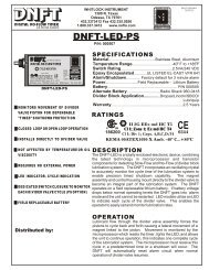
DNFT DNFTR<br />
DIGITAL NO-FLOW TIMER<br />
U.S. PAT. NO. 5,835,372<br />
HEX MAGNET<br />
HOUSING<br />
MAGNET<br />
O-RING<br />
SET SCREWS<br />
SPACER SPRING<br />
FIELD REPLACEABLE<br />
BATTERY<br />
P/N 000505<br />
WHITLOCK INSTRUMENT<br />
1300 N. Texas<br />
Odessa, TX 79761<br />
915.3373412 Fax 915.335.5926<br />
1.800.337.3412 www.noflo.com<br />
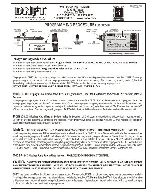
PROGRAMMING PROCEDURE FOR 000518<br />
1/8" RECESSED OPENING<br />
FOR PROGRAMMING MAGNET<br />
1/2" PIPE PLUG<br />
PROGRAMMING<br />
MAGNET<br />
SPRING LOADED<br />
MAGNET ASSEMBLY<br />
LED<br />
(LIGHT EMITTING DIODE)<br />
ALLEN HEAD<br />
SET SCREWS (2)<br />
LCD (LIQUID CRYSTAL DISPLAY)<br />
Programmable w/Replaceable <strong>battery</strong> PRG<br />
Programming Modes Available:<br />
MODE 1- Displays Total Divider Valve Cycles. Program Alarm Time in Seconds. MAX: 255 Sec. (4 Min. 15 Sec.) MIN: 20 Seconds<br />
MODE 2 - Displays Cycle Time of Divider Valve in Seconds<br />
MODE 3 - Displays Total Pints. Program Divider Valve Total: Maximum of 120<br />
MODE 4 - Displays Pump Rate in Pints Per Day<br />
To program the DNFT, the programming magnet must be inserted into the 1/8" recessed opening located on the face of the DNFT. To change<br />
programming mode, remove and re-insert the programming magnet into the recessed opening. The current programming mode 1,2,3 or 4 will<br />
immediately be displayed followed by a "0" 2 seconds later. This "0" indicates that the current mode may be programmed.<br />
NOTICE: DNFT MUST BE PROGRAMMED BEFORE INSTALLATION ON DIVIDER BLOCK.<br />
Mode 1 - LCD Displays Total Divider Valve Cycles. Program Alarm Time MAX: 4 Minutes 15 Seconds (255 seconds)MIN: 20<br />
Seconds<br />
Insert programming magnet into the 1/8" recessed opening located on the face of the DNFT. If mode 1 is not selected in display, remove and reinsert<br />
programming magnet until the LCD indicates mode 1. Do not remove programming magnet when mode 1 is displayed. To set alarm time,<br />
depress and release spring loaded magnet assembly until desired alarm time (in seconds) is displayed on the LCD. Example: 60 counts on LCD<br />
=60 second alarm time. Remove programming magnet. DNFT will display total divider valve cycles if left in this mode and is now set for 60<br />
Mode 2 - LCD Displays Cycle Time of Divider Valve in Seconds. LCD will count each cycle of the divider valve in seconds, counting<br />
up from "0" until the divider valve completes one full cycle. When divider valve completes one full cycle, the LCD will reset to zero and begin<br />
counting each second until another cycle is completed.<br />
Mode 3 - LCD Displays Total Pints Used. Program Divider Valve Total in This Mode. MAXIMUM DIVIDER VALVE TOTAL: 120<br />
Insert programming magnet into 1/8" recessed opening located on the face of the DNFT. If mode 3 is not selected in display, remove and reinsert<br />
programming magnet until the LCD indicates mode 3. Do not remove programming magnet when mode 3 is displayed. To program divider<br />
valve total, add the total of the divider valve assembly on which the DNFT will be installed. Example: 24 + 24 + 24 = 72. Enter the total of the<br />
divider valve assembly by depressing and releasing the spring loaded magnet until the divider valve total is displayed on the LCD. When the total<br />
of the divider valve assembly is displayed, remove the programming magnet. The DNFT is now programmed and will record total pints on the<br />
LCD if left in mode3. The LED blinks in all modes to indicate each divider valve cycle. This blink enables the operator to set pump rate.<br />
Mode 4 - LCD Displays Pump Rate in Pints Per Day . FOUR (4) SECOND MINIMUM CYCLE TIME.<br />
U.S. PAT. NO. 5,835,372 R<br />
WHITLOCK<br />
INSTRUMENT<br />
ODESSA, TX USA<br />
DIGITAL NO-FLOW TIMER<br />
002196<br />
518LIT PRG-WI-4<br />
06.06.01<br />
CYCLE INDICATION<br />
INSTRUMENT<br />
ODESSA, TX USA<br />
MODEL PRG<br />
Factory Sealed<br />
RATED 2.5VA/240VDC<br />
II 2G EEx m IIB T5<br />
R<br />
P/N<br />
Cl I; Zone 1; Ex md IIC T4 CE<br />
C US<br />
Cl I; Div 1; Grps. A,B,C,D;T4 0344 SERIAL #<br />
186200<br />
KEMA 00ATEX1090 X Amb. -40° C...+85°C ALARM PROGRAMMABLE<br />
ORANGE-SWITCH GRN-GND. VIO - OPEN - N.O. VIO - SHORT - N.C.<br />
CAUTION: DO NOT INSERT PROGRAMMING MAGNET IN THE RECESSED OPENING WHEN THE UNIT IS MOUNTED ON DIVIDER<br />
VALVE WITH COMPRESSOR RUNNING. DNFT WILL GO INTO ALARM AND COMPRESSOR WILL SHUTDOWN. MODES CANNOT BE<br />
CHANGED WHILE DNFT IS MOUNTED ON DIVIDER VALVE WITH COMPRESSOR RUNNING.<br />
DNFT must be removed from the divider valve to change modes. After removing DNFT from divider valve, operator may change to any mode by<br />
inserting and removing programming magnet until desired mode is displayed by LCD. Please Note: DNFT will store all programmed information<br />
until programming magnet is inserted and spring loaded magnet is depressed. If spring loaded magnet is depressed with programming magnet<br />
in place, unit defaults to zero and must be reprogrammed.<br />
1-800-337-3412<br />
www.noflo.com<br />
1-800-337-3412<br />
WHITLOCK<br />
www.noflo.com