Combustion Technologies By-Pass Filtration Instructions
Combustion Technologies By-Pass Filtration Instructions
Combustion Technologies By-Pass Filtration Instructions

You also want an ePaper? Increase the reach of your titles
YUMPU automatically turns print PDFs into web optimized ePapers that Google loves.
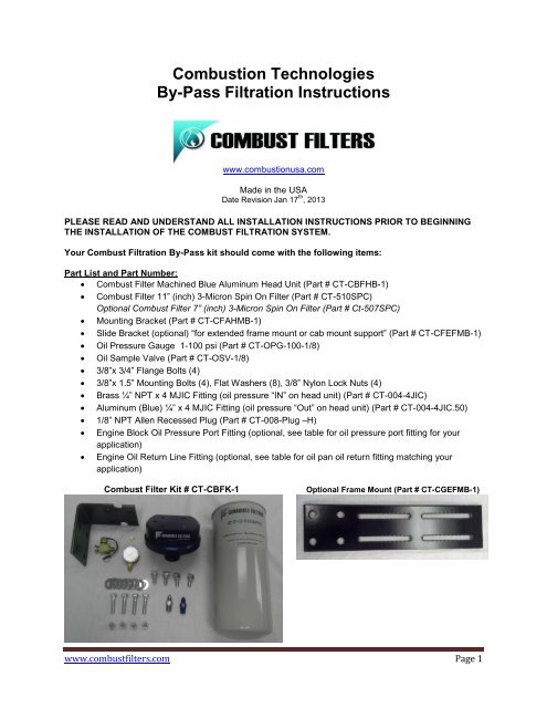
<strong>Combustion</strong> <strong>Technologies</strong><strong>By</strong>-<strong>Pass</strong> <strong>Filtration</strong> <strong>Instructions</strong>www.combustionusa.comMade in the USADate Revision Jan 17 th , 2013PLEASE READ AND UNDERSTAND ALL INSTALLATION INSTRUCTIONS PRIOR TO BEGINNINGTHE INSTALLATION OF THE COMBUST FILTRATION SYSTEM.Your Combust <strong>Filtration</strong> <strong>By</strong>-<strong>Pass</strong> kit should come with the following items:Part List and Part Number: Combust Filter Machined Blue Aluminum Head Unit (Part # CT-CBFHB-1) Combust Filter 11” (inch) 3-Micron Spin On Filter (Part # CT-510SPC)Optional Combust Filter 7” (inch) 3-Micron Spin On Filter (Part # Ct-507SPC) Mounting Bracket (Part # CT-CFAHMB-1) Slide Bracket (optional) “for extended frame mount or cab mount support” (Part # CT-CFEFMB-1) Oil Pressure Gauge 1-100 psi (Part # CT-OPG-100-1/8) Oil Sample Valve (Part # CT-OSV-1/8) 3/8”x 3/4” Flange Bolts (4) 3/8”x 1.5” Mounting Bolts (4), Flat Washers (8), 3/8” Nylon Lock Nuts (4) Brass ¼” NPT x 4 MJIC Fitting (oil pressure “IN” on head unit) (Part # CT-004-4JIC) Aluminum (Blue) ¼” x 4 MJIC Fitting (oil pressure “Out” on head unit) (Part # CT-004-4JIC.50) 1/8” NPT Allen Recessed Plug (Part # CT-008-Plug –H) Engine Block Oil Pressure Port Fitting (optional, see table for oil pressure port fitting for yourapplication) Engine Oil Return Line Fitting (optional, see table for oil pan oil return fitting matching yourapplication)Combust Filter Kit # CT-CBFK-1Optional Frame Mount (Part # CT-CGEFMB-1)www.combustfilters.com Page 1
Safety Precautions: Before beginning work, ensure the engine has sufficiently cooled to prevent burn injuries. Installation of this filter should be performed by a qualified technicianGeneral Precautions: Always wear safety glasses and other necessary protective gear during the installation of your<strong>Combustion</strong> <strong>Technologies</strong> Oil <strong>By</strong>-<strong>Pass</strong> <strong>Filtration</strong> SystemNotes for all Hose Connections: If using non-crimped fittings for your hose assemblies use a heat gun or soak the hose ends inhot water to expand them to ease assembling hoses over barbed fittings. Be sure to shake offany water from the hoses. Apply light oil such as silicon spray or penetrating spray inside the hose end to ease theassembly of the adaptor into the hose end. DO NOT use grease or engine oil for this purpose. Slide a ½” hose over each ¼” hose at those places where the hose comes close to moving orvibrating parts. This is to protect the ¼” hose from abrasion. Also add the ½” hose to the parts ofthe hose that bend. This will help the ¼” hose hold its shape and prevent crimping. Route all hoses away from extremely hot components, such as exhaust pipes and the turbo. Route all hoses away from moving parts, such as the radiator fan, belts and pulleys. Use ties to secure the hoses in place. Ensure the hose is the proper length before sliding them over the barbed hose fitting, as hosesmust be cut to be removed from the fittings. Leave a slight amount of slack in the hose to allow for engine vibration. Use Liquid Teflon on all NPT threads. (Teflon Tape not recommended)Before Installing the <strong>Combustion</strong> <strong>Technologies</strong> <strong>By</strong>-<strong>Pass</strong> <strong>Filtration</strong> System: It is recommended that you perform an oil change on the vehicle as part of the installation of thissystem. Be sure to handle used oil in compliance will all applicable laws. This will usually include makingprovisions for recycling. Always wear oil resistant gloves when handling used oil. It is recommended that you take an oil sample test of the used oil. This sample can then be usedas a “Base Line” to compare with future samples.Technical Support ...........................................................Call Toll Free 866-680-3055Web Information…………… http://www.combustionusa.com/<strong>By</strong>-<strong>Pass</strong>_<strong>Filtration</strong>.htmlwww.combustfilters.com Page 2
Installation of your <strong>Combustion</strong> <strong>Technologies</strong> <strong>By</strong>-<strong>Pass</strong> <strong>Filtration</strong> System1. Position bracket and use as a template to mark and drill (4) 3/8” holes.Note: Make sure that there is room for removal and service of the filter and that it is clear ofsteering components, axle movement, hood access, or other moving parts when looking for asuitable mounting location.NOTE: Before drilling into the frame, check inside the frame rail for hoses or wiring that may berouted there. If hoses or wiring are present, move them out of the way or select a differentlocation on which to mount the filter.See Illustration 1:Illustration # 12. Attach steel mounting bracket to frame rail using supplied 3/8” x 1.5” bolts, washers, Nylonlocknuts.See illustration 2:Illustration # 2www.combustfilters.com Page 3
3. Attach the <strong>Combustion</strong> <strong>Technologies</strong> <strong>By</strong>-<strong>Pass</strong> <strong>Filtration</strong> head unit to the mounting bracket usingsupplied 3/8” x 3/4” Flange Bolts.See illustration 3:Illustration # 34. On each side of the oil pressure “IN” port is a 1/8” NPT port for the supplied Oil Sample Valve.Choose the port that is best suited for your application and install the Oil Sample Valve.See illustration 4:5. Use the supplied 1/8” NPT Allen head plug to seal the other port not in use.See illustration 4:6. Install Steel/Brass ¼” NPT x 4 JIC fitting to the “IN” oil port on the aluminum head unitSee illustration 4:Illustration # 4www.combustfilters.com Page 4
7. Install aluminum (blue) ¼” NPT x 4 JIC fitting to the “OUT” oil port on the aluminum head unit.Note: This aluminum fitting has been flow tested and must be used only on the “OUT” oil port forthe oil pressure gauge to work correctly.See illustration 5 & 5.1Illustration # 5 Illustration # 5.18. Install the supplied oil pressure gauge in the 1/8” NPT port located on the top of the BlueCombust Filter Head. Face the gauge so the dial is visible for easy inspection and does notinterfere with any moving parts. This gauge will allow you to determine the oil pressure at start-upof your engine as well as tell you when the Combust Spin-On Filter needs to bechanged/replaced. (Please read Servicing your filter on page 7 of the instructions)Note: Always use liquid Teflon instead of tape when installing fittings and gauges into analuminum material. This will help protect the threads from stretching and allow for a nice seal.See illustration 6:Illustration # 6www.combustfilters.com Page 5
9. Locate a suitable oil pressure port on engine block, oil filter housing, or other location and installnecessary fitting. We do not recommend using the turbo oil feed line. Refer to your owner’smanual if necessary.See illustration 7 & 7.1Illustration # 7 Illustration 7.110. Route and install oil supply line to the ¼” NPT x 4 JIC on the (IN) port of the <strong>Combustion</strong><strong>Technologies</strong> <strong>By</strong>-<strong>Pass</strong> <strong>Filtration</strong> Aluminum Head Unit. Secure oil supply line with wire ties asneeded. Make sure that the oil supply line will not rub on moving parts or melt or burn on theexhaust and turbo.See illustration 8Illustration # 8www.combustfilters.com Page 6
11. Locate a suitable location for the oil return line. The oil pan is preferred in most cases. Otherpossible locations include the oil fill tube or cap, valve cover, front engine cover, or other nonpressurelocation that will return the clean oil to the sump. Refer to your owner’s manual ifnecessary.See illustration 9 & 9.1:Illustration # 9 Illustration # 9.112. Install the correct fitting for your application to the selected oil return port.13. Route the oil return line in a similar manner. Use care and avoid rubbing and close proximity toheat sources. Secure with wire ties and protective covering as needed.14. Install the replaceable Combust Spin on Filter (Part # CT-510SPC or CT-507SPC) to the bluealuminum head unit.15. Use a small amount of oil on the rubber seal and hand tighten. Do not prefill filter with oil.Note: BEFORE STARTING YOUR ENGINE: MAKE SURE YOU HAVE CHECKED THE OIL FOR THEPROPER LEVEL AND THAT ALL FITTINGS, HOSES, FILTERS AND GAUGES ARE INSTALLEDCORRECTLY!Operational Testing: Check and fill all oil levels before operational testing.Note: (DO NOT PREFILL THE COMBUSTION TECHNOLOGIES SPIN ON FILTER) Start Engine Look at the oil pressure gauge on the top of the aluminum head unit and watch for pressure.(This could take a couple of minutes as the filter is being filled) When pressure is indicated you will know that the filter is full and the oil is flowing correctly. Check for leaks. If a leak is detected shut-off the engine and repair as needed. Shut off engine and check oil level. Fill to proper level. The <strong>Combustion</strong> <strong>Technologies</strong> Spin on Filter holds approximately 2.5 quarts of oil.www.combustfilters.com Page 7
Road Test:After the installation is complete you will want to go on a road test. It is important that you periodicallycheck the <strong>Combustion</strong> <strong>Technologies</strong> <strong>By</strong>-<strong>Pass</strong> <strong>Filtration</strong> System for leaks, rubbing on hoses, and bolts thatmay have vibrated loose. Always check fluid levels and monitor gauges for safe operation.Note: Never run an engine that is low on oil!Servicing:Replacing the Spin-On Filter Element(The pressure gauge that comes with the kit (illustration # 6) will help determine when your spinonCombust Filter may need to be replaced. Please note the pressure at start up after the enginehas come to the operating temperature. (Example 60-psi) Once your Combust Spin-On Filter hasbecome full of contamination and water, the pressure gauge should show a drop in reading whichindicates it is time to replace the filter. (Example 15-psi)Replace the <strong>Combustion</strong> <strong>Technologies</strong> spin-on filter at the oil service interval recommended by themanufacturer. (See your owner’s manual) The manufactures recommended oil change interval is a safestarting point to do an oil analysis and safely extend oil change intervals. Make sure your engine is at a safe temperature to work on to avoid burn injuries Place an oil drain pan below the filter in case of a spill Remove the used filter by hand or with a filter wrenchBefore installing the new filter, lubricate the new rubber seal with clean oil (DO NOT pre-fill filter)Tighten the replacement <strong>Combustion</strong> <strong>Technologies</strong> filter by hand until the gasket contacts thebase and ensure proper seating of the filter and new gasket.Note: (DO NOT USE A FILTER WRENCH AND DO NOT OVER TIGHTEN)Start Engine and run until oil pressure is indicated on the oil pressure gauge on the top of thealuminum head unit. This insures that the filter is full.Check for leaksStop engine. Check oil level and fill as requiredWe recommend that you change the <strong>Combustion</strong> <strong>Technologies</strong> Filter every normal service interval asrecommend by the engine manufacturer. The OEM Full Flow Filters should be changed at a maximum of 1 year or 80,000 miles. Take Oil Samples at the normal service interval (as recommend by the manufacturer). Shorten this interval if the results of the previous oil test indicated a potential problem.Oil Sample Procedure:Start the engine and bring the engine to normal operating temperature.With the engine running, remove the safety cap on Oil Sample Valve (part #7). To ensure anaccurate sample reading, purge the sampling valve to flush out impurities that may have settled inthe valve opening.Hold the clean sample bottle under the sample valve and push on the button until bottle is filled tocorrect level.Screw cap tightly onto the sample bottleScrew the Safety Cap back onto the Sample ValveFill out documentation forms will all the necessary information required by your lab and returnwith oil sample to your test facility.Oil Sample Testing is the only way to safely extend oil drain intervals. Working with a qualified testingfacility can help you determine when an oil change is needed. Your new <strong>Combustion</strong> <strong>Technologies</strong> <strong>By</strong>-<strong>Pass</strong> <strong>Filtration</strong> System can safely extend oil change intervals, reduce engine wear, reduce waste oildisposal costs, and increase fuel efficiency by simply keeping the oil clean!www.combustfilters.com Page 8
Engine Manufacture Port Fitting Size ChartEngineOil Pressure Port Fitting SpecificationsCaterpillar 34061/4" Male NPTF to 1/4" Hose Barb fittingCaterpillar 34081/4" Male NPT to 1/4" Hose Barb fittingCat C-77/16 x # 4 JIC Adapter to # 4 JIC to 1/4" Barb FittingCat C-9# 4 O-ring x # 4 JIC to # 4 JIC to # 4 barbCat C13Tap oil pressure gauge lineCat C151/4" NPT on filter block or 7/16" O-ring x 4 JIC to 1/4" Hose barb fittingon the sending unit blockCummins B5.91/4" NPT Tee or #4 JIC Branch Tee or 1/8" NPT TeeCummins ISM 200514mm x 1.5 plug or 14mm x # 4 JICCummins ISX14mm x 1.5 plug on oil coolerCummins M111/2" Boss O-Ring, 1/4" Male NPTF to 1/4" Hose Barb fittingCummins N141/2" Boss O-Ring, 1/4" Male NPTF to 1/4" Hose Barb fittingDetroit Diesel 60 Series1/4" Male NPTF to 1/4" Hose Barb fittingDetroit Diesel 60 Series 1/8" NPTF Tee with 1 male and 2 females fitting, 1/8" Male NPTF to 1/4"Hose Barb fittingDetroit Diesel 60 Series1/4" Oil Pressure ports (2) located on <strong>Pass</strong>enger side behind exhaustDetroit Diesel 60 Series1/4" JIC Tee or #4 JIC Branch TeeDetroit Diesel DD1333mm-2.0 X 1/2" NPTDetroit Diesel DD1533mm-2.0 X 1/2" NPTInternational DT 466#4 Branch Tee to # 4 JIC hose barbIsuzu NPR 1/8" NPTF Tee with 1 male and 2 females fitting, 1/8" Male NPTF to 1/4"Hose Barb fittingJohn Deere 1/8" NPTF Tee with 1 male and 2 females fitting, 1/8" Male NPTF to 1/4"Hose Barb fittingJohnston1/8" Male NPTF to 1/4' Hose BarbKomatsu1/8" Male NPTF to 1/4' Hose BarbMack E71/4" NPT to 1/4" Hose BarbMack 427 & 4541/4" NPT to 1/4" Hose BarbMack 460-E1/4" Male NPTF to 1/4' Hose BarbMack MP7 - M816 MM Male w/O-Ring x ¼” NPT FemaleMercedes 900 SeriesM14 under filter housing storm to 1/4" hose barbMercedes 400014mm x # 4 JIC to # 4 JIC x 1/4" Hose BarbPerkins F406(3/8 x 1/4 FE Coupler) to 1/4" barbVolvo 5.0 1/8" NPTF Tee with 1 male and 2 females fitting, 1/8" Male NPTF to 1/4"Hose Barb fittingVolvo VED1216mm x 1.5 plug x 1/4" NPT to 1/4" Hose Barb FittingVolvo VE1610mm x 1.5 x 1/8" NPT to 1/8" 90 degree elbow to 1/8" NPT x 1/4" barbYanmar Marine1/8" Male NPTF to 1/4' Hose Barb*Check your owner’s manual or consult your OEM dealer for additional pressure port locationswww.combustfilters.com Page 9